31000-16-10-15-030-03-02 | Bently Nevada | 31000 Proximity Probe Housing
Technical Overview
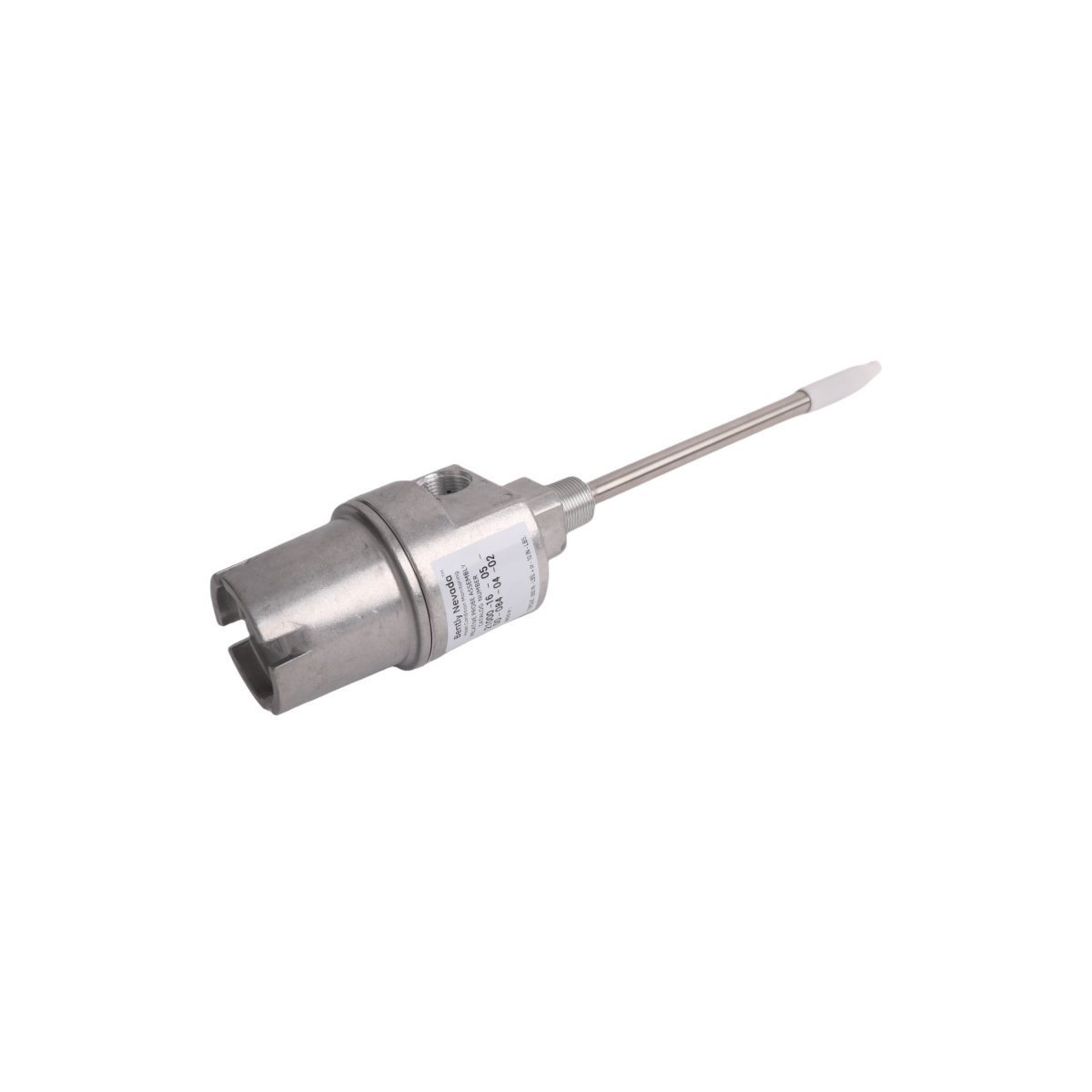
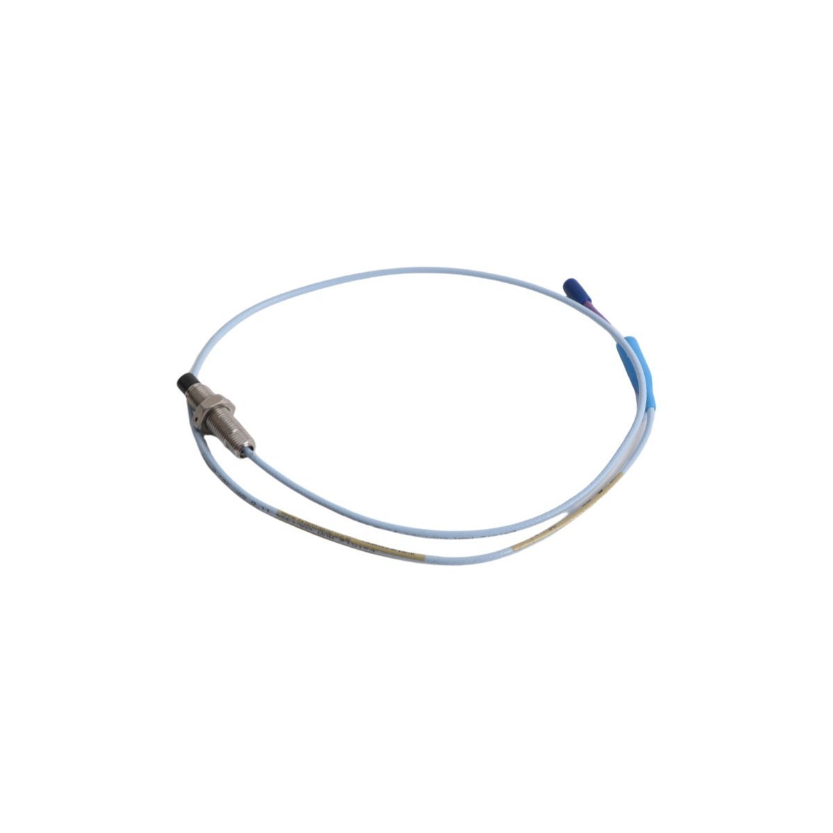
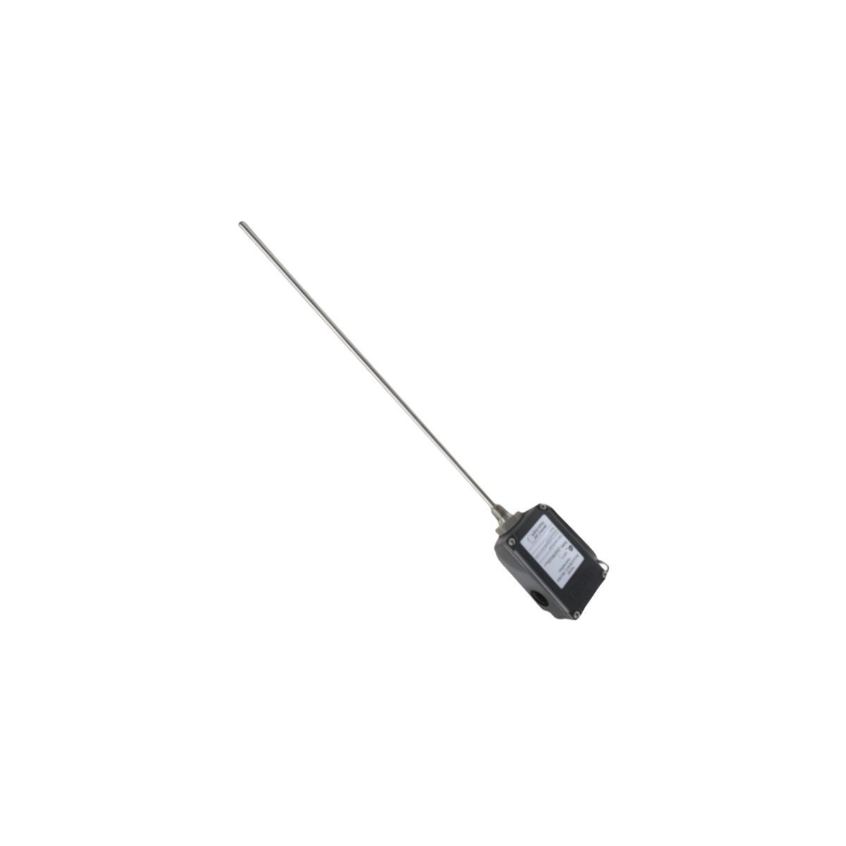
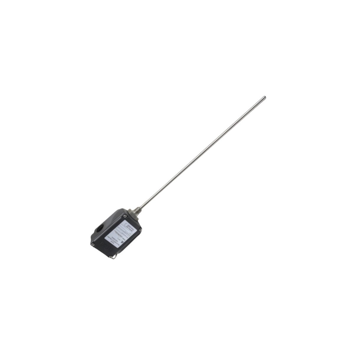
The Bently Nevada 31000-16-10-15-030-03-02 is a specialized proximity probe housing designed to physically protect a proximity probe and its integral cable within harsh industrial environments. Its primary function is to provide a secure, environmentally sealed mounting point on rotating machinery for acquiring critical vibration and position data. The housing is constructed from 304 Stainless Steel, offering robust protection against physical impact and corrosion. This specific configuration, 31000-16-10-15-030-03-02, features a 3/4-14 NPT external mounting thread for direct installation into a machine case. Internally, it accommodates a Bently Nevada 3300 XL 8 mm or 3300 5 mm probe, which is positioned by a 1.0-inch stinger (probe sleeve). The housing facilitates the signal path from the probe tip to the Bently Nevada 3500 Monitoring System. The probe, connected via an extension cable to a Proximitor Sensor, generates a high-frequency RF signal. The resulting eddy current field is used to measure the distance to the observed conductive target. The Proximitor Sensor conditions this signal into a calibrated DC voltage proportional to the gap, which is then transmitted to a 3500/42M Proximitor/Seismic Monitor module for analysis, alarming, and machinery protection.
Detailed Specifications
| Parameter | Specification |
|---|---|
| Manufacturer | Bently Nevada |
| Part Number | 31000-16-10-15-030-03-02 |
| Product Type | 31000 Proximity Probe Housing |
| Condition | Brand New |
| Warranty | 12 Months |
| Housing Material | 304 Stainless Steel |
| Mounting Thread | 3/4-14 NPT |
| Stinger (Probe Sleeve) Length | 1.0 inch (25.4 mm) |
| Probe Compatibility | Bently Nevada 3300 XL 8 mm and 3300 5 mm Proximity Probes |
| Environmental Sealing | Viton O-ring cable seal included |
| Operating Temperature Range | -34 °C to +177 °C (-30 °F to +350 °F) |
| Hazardous Area Suitability | Suitable for Class I, Div 2 / Zone 2 locations when installed per Bently Nevada control drawings and with appropriately certified system components. |
Operational Capabilities
In Oil & Gas applications, the 31000-16-10-15-030-03-02 housing provides essential protection for transducers monitoring centrifugal and reciprocating compressors, pumps, and gearboxes. Its 304 Stainless Steel construction and Viton seals ensure long-term integrity in environments containing corrosive elements such as H2S and hydrocarbons, a critical requirement for meeting API 670 standards for machinery protection systems. In Power Generation, this housing is extensively used on steam and gas turbines, exciters, and boiler feed pumps. It maintains measurement accuracy and reliability under conditions of high temperature and vibration, which is fundamental for monitoring shaft radial vibration, axial thrust position, and differential expansion. The passive mechanical design results in a high Mean Time Between Failures (MTBF), contributing to overall plant availability. When properly installed, the housing assembly provides an environmental rating equivalent to NEMA 4X and IP65, preventing ingress of dust, moisture, and process contaminants that could otherwise compromise signal integrity