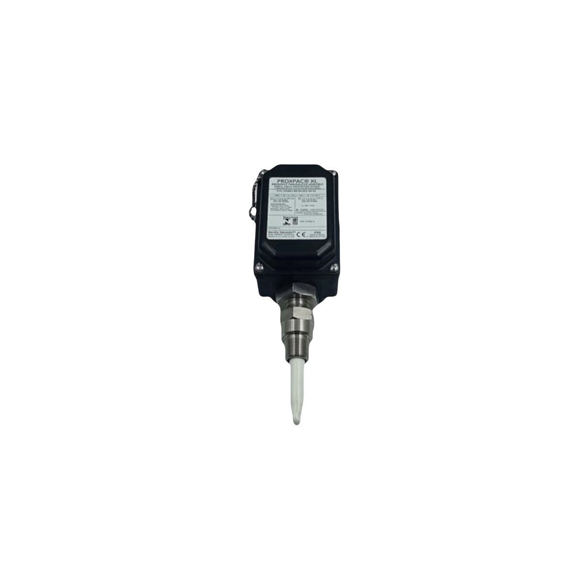
330881-28-04-034-06-02 | Bently Nevada | PROXPAC XL Proximity Transducer
Technical Overview
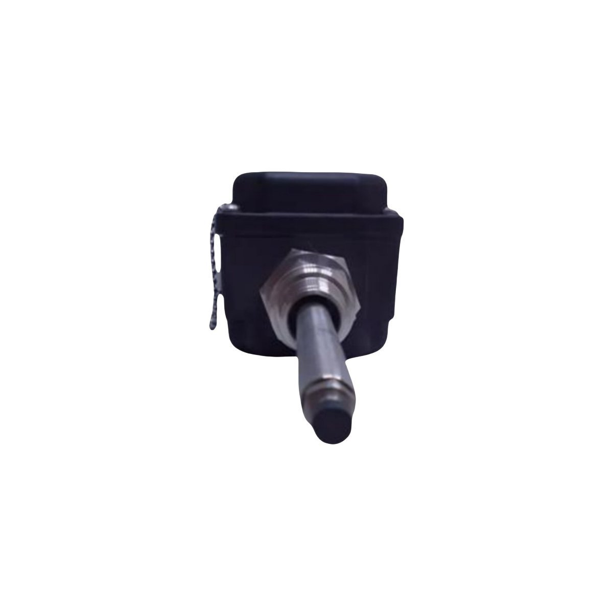
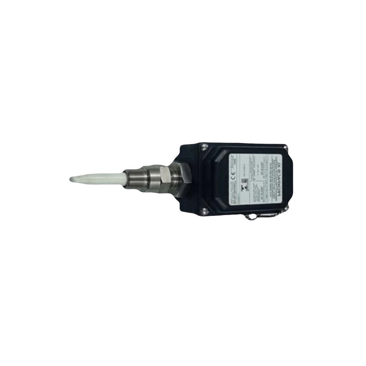
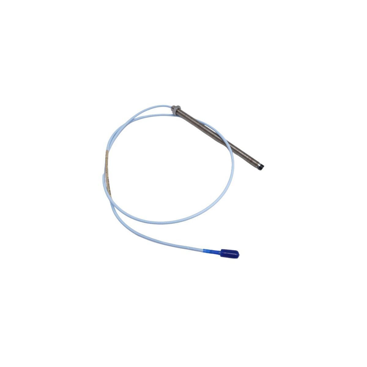
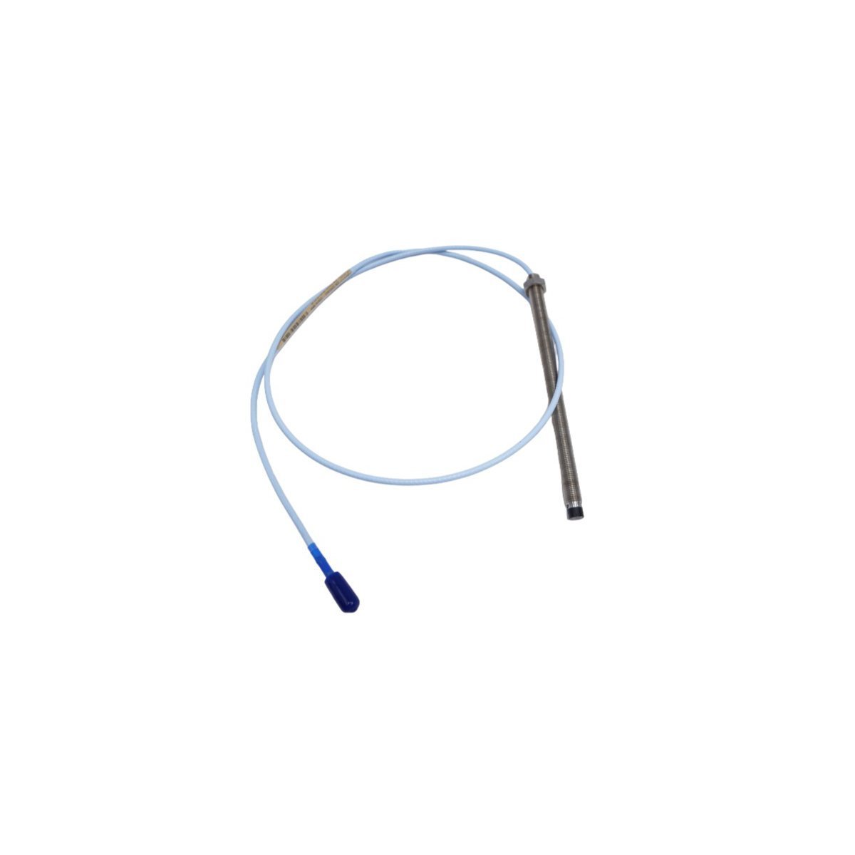
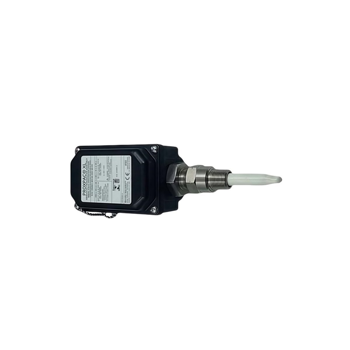
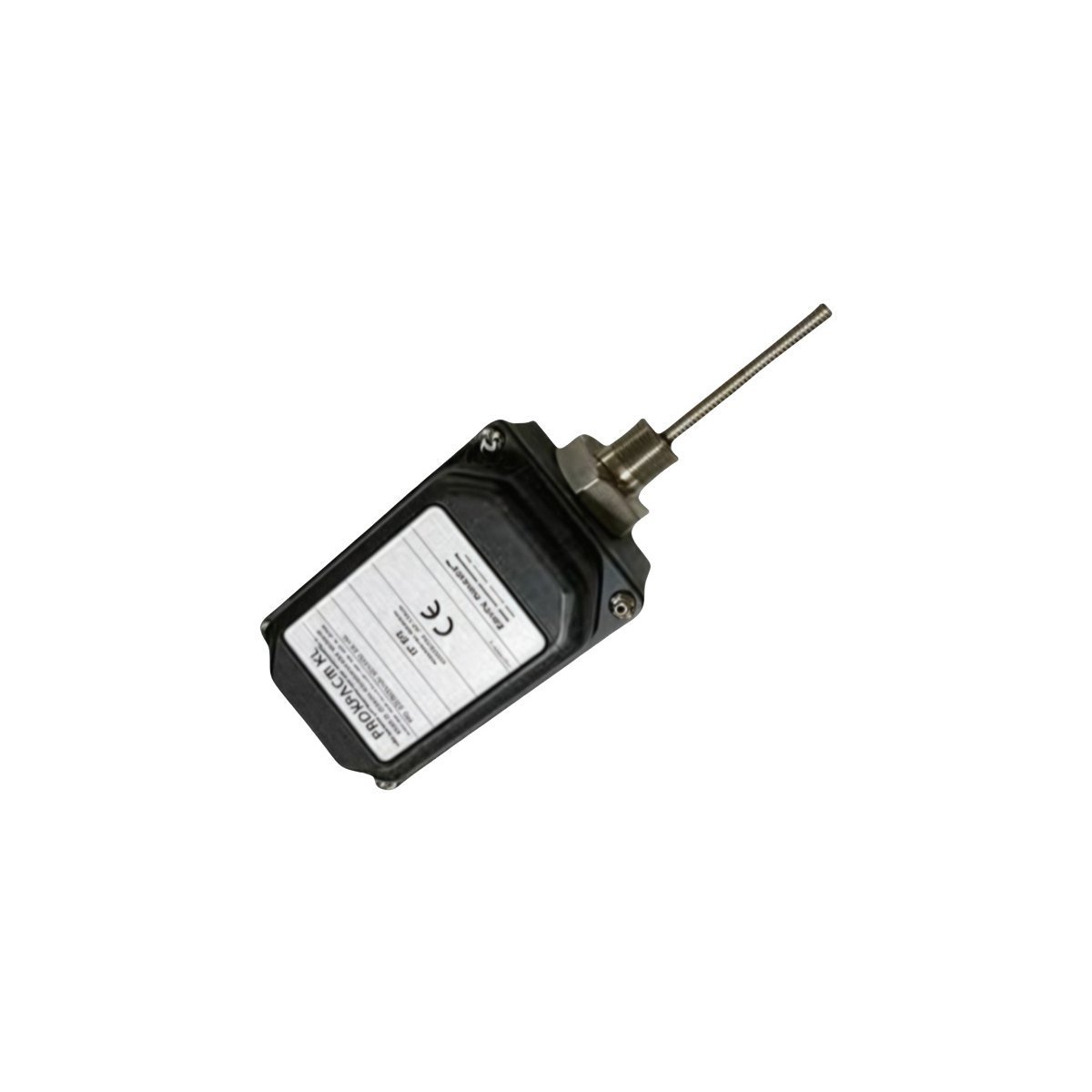
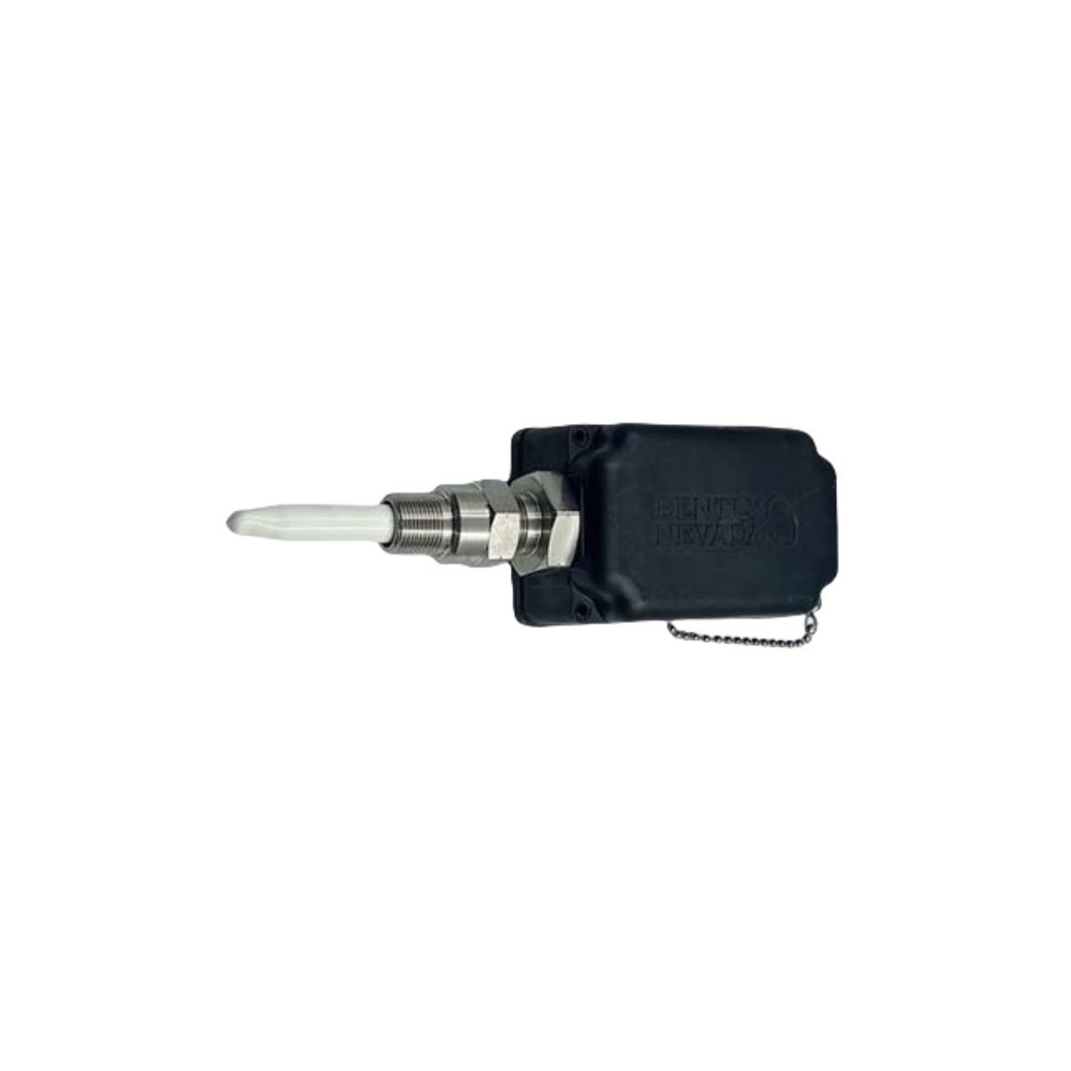
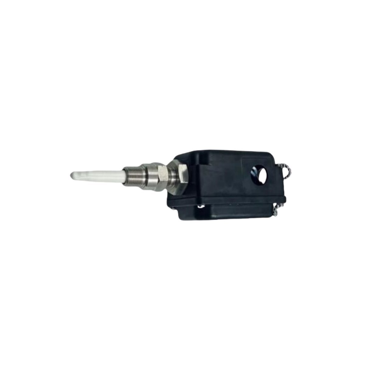
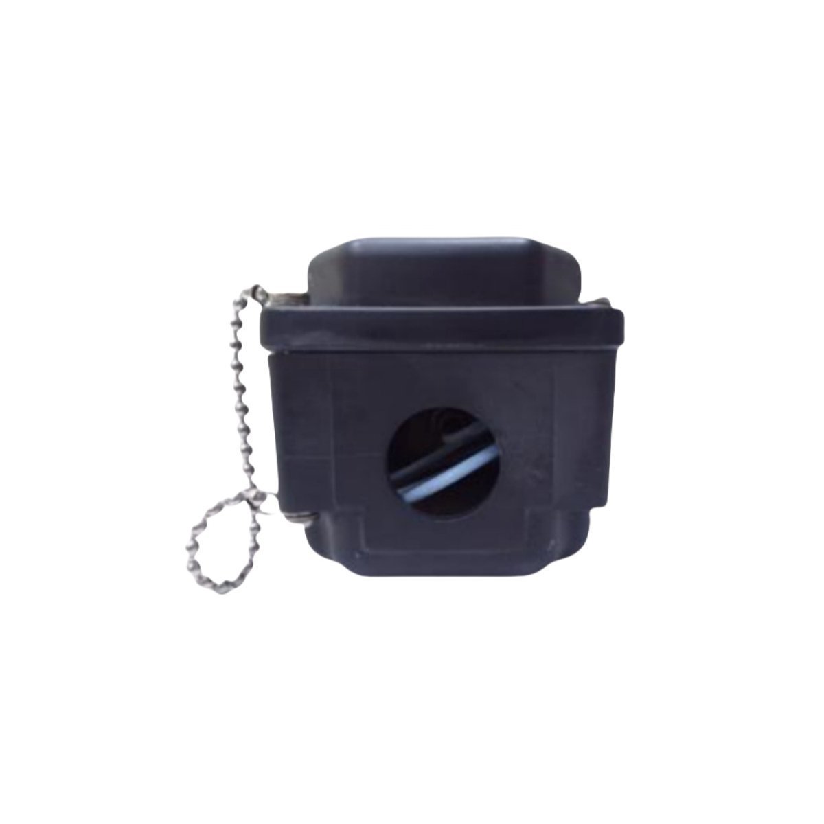
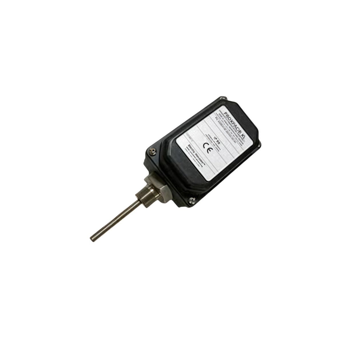
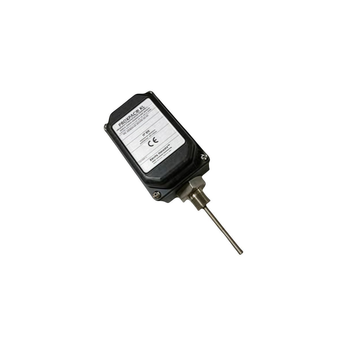
The Bently Nevada 330881-28-04-034-06-02 is an integrated PROXPAC XL Proximity Transducer system. This component combines an 8 mm proximity probe, an extension cable, and a signal conditioner into a single, factory-calibrated assembly, which eliminates the need for individual component calibration in the field. The transducer operates on the eddy current principle. The probe tip emits a high-frequency radio frequency (RF) signal, which induces eddy currents on the surface of a conductive machine element, such as a rotating shaft. The transducer's internal circuitry measures the impedance changes resulting from the interaction between the RF field and the eddy currents. This impedance is directly proportional to the physical gap between the probe tip and the target surface. The integrated signal conditioner demodulates this signal and provides a continuous DC voltage output that is precisely proportional to the measured gap. This output voltage is then transmitted to a monitoring system, such as the Bently Nevada 3500 series, for analysis of vibration, axial position, or rotational speed. The construction of the 330881-28-04-034-06-02 ensures high signal integrity by minimizing interconnections, making it suitable for critical machinery monitoring applications.
Detailed Specifications
| Parameter | Specification |
|---|---|
| Manufacturer | Bently Nevada |
| Part Number | 330881-28-04-034-06-02 |
| Product Type | PROXPAC XL Proximity Transducer |
| Condition | Brand New |
| Warranty | 12 Months |
| Total System Length | 2.8 metres (9.2 feet) |
| Probe Configuration | 3300 XL 8 mm probe, 1/4-28 UNF thread, 0.5 m cable |
| Agency Approvals | Multiple Approvals: CSA (Class I, Div 1/2); ATEX/IECEx (Zone 0/1) |
| Scale Factor | 8.0 V/mm (200 mV/mil), ±5% for AISI 4140 Steel |
| Linear Range | 2.0 mm (80 mils), beginning at 0.25 mm (10 mils) from the probe face |
| Frequency Response | 0 Hz (DC) to 10 kHz (-3 dB) |
| Power Supply Requirement | -17.5 Vdc to -26 Vdc at 12 mA maximum consumption |
| Mounting Option | Panel Mount, 4-Hole Square Flange |
Operational Capabilities
In Oil & Gas and Power Generation applications, the 330881-28-04-034-06-02 provides continuous, online data for machinery protection and condition monitoring. It is engineered for measuring radial vibration, axial thrust position, and differential expansion on large rotating equipment such as gas and steam turbines, centrifugal and reciprocating compressors, and large pump motors. The integrated design enhances reliability by eliminating the connectors between the probe, extension cable, and Proximitor sensor, which are common points of failure and signal degradation due to moisture ingress or vibration. The factory-calibrated system ensures measurement consistency and accuracy without field adjustments. Environmentally, the 330881-28-04-034-06-02 is specified with multiple agency approvals (CSA, ATEX, IECEx), certifying it for safe operation in hazardous areas with explosive gas atmospheres (e.g., Class I, Division 1; Zone 0). The electronics housing is rated for an operating temperature of -34 °C to +85 °C (-30 °F to +185 °F), ensuring performance in demanding industrial environments.
Applications
- Power generation turbines and generators
- Oil & gas compressors and pumps
- Industrial rotating machinery monitoring
- Predictive maintenance systems
- Process automation
Technical FAQ
Q: What systems is the 330881-28-04-034-06-02 compatible with?
A: The 330881-28-04-034-06-02 is fully compatible with the Bently Nevada 3500 Machinery Protection System, specifically interfacing with modules such as the 3500/42M Proximitor/Seismic Monitor. It is also compatible with any PLC, DCS, or data acquisition system that can provide a -17.5 Vdc to -26 Vdc power supply and accept a proportional analog voltage input (typically configured for a range like -2 to -18 Vdc). The transducer is factory-calibrated for AISI 4140 steel; use with other target materials will require a different calibration or result in measurement inaccuracies.
Q: What are the installation requirements?
A: Installation requires both mechanical mounting and electrical wiring. The probe portion, with its 1/4-28 UNF thread, must be installed in a rigid bracket and its gap set relative to the machine shaft. The standard practice is to set the DC gap voltage to the center of the linear range (e.g., -10.0 V