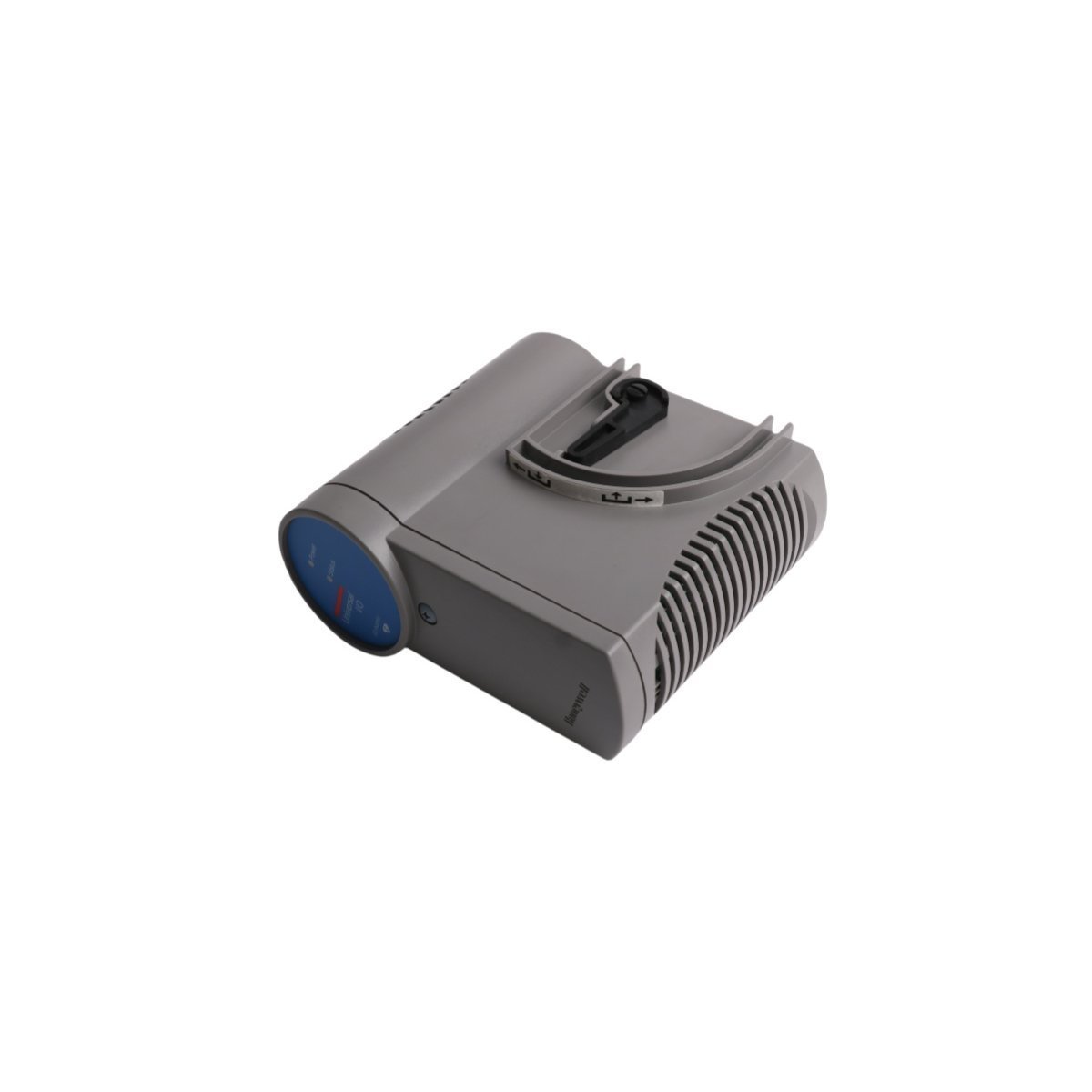
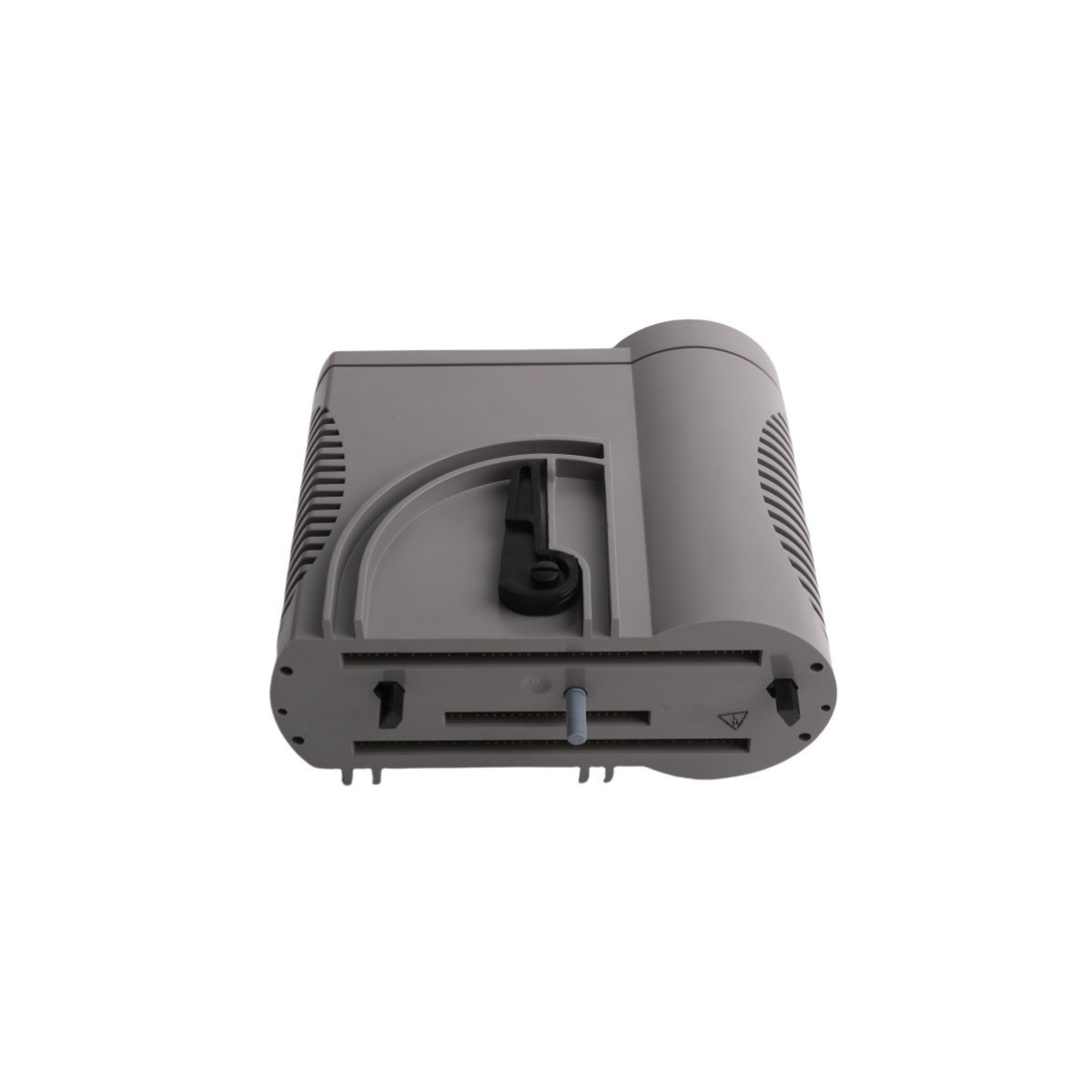
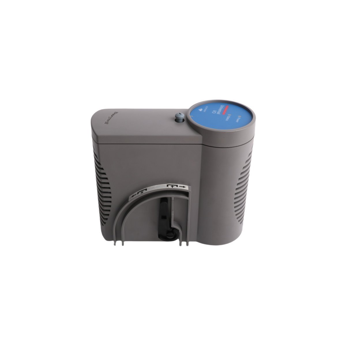
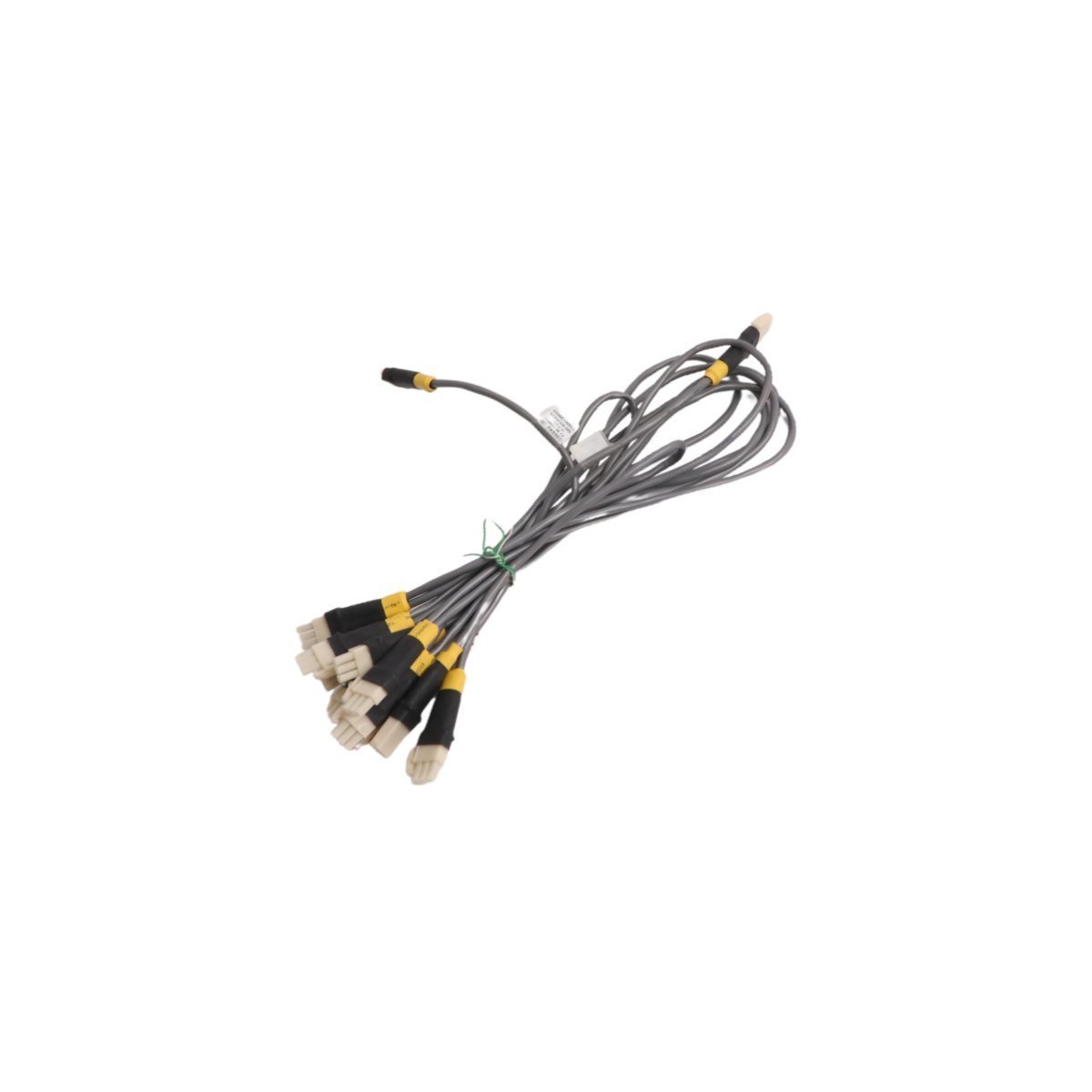
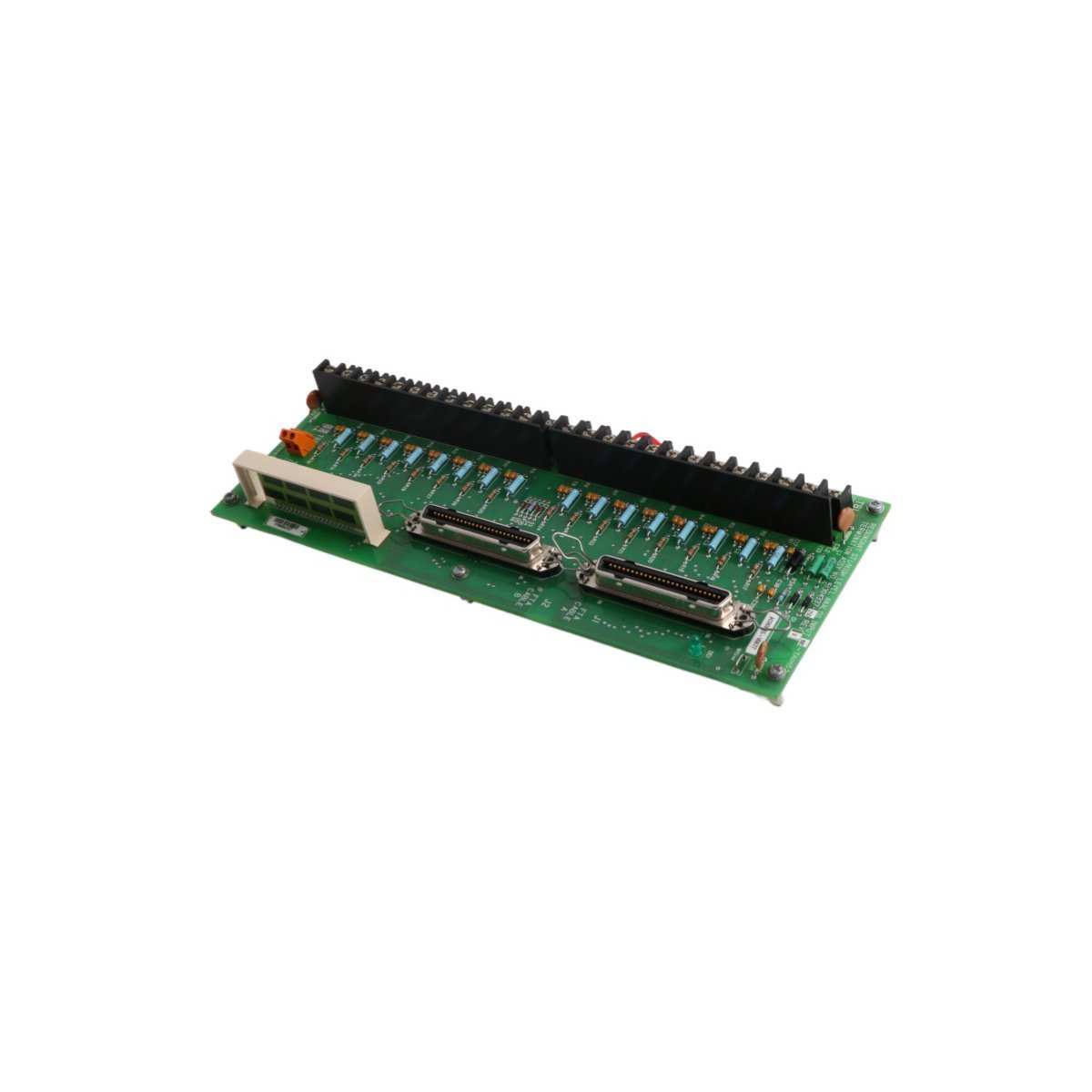
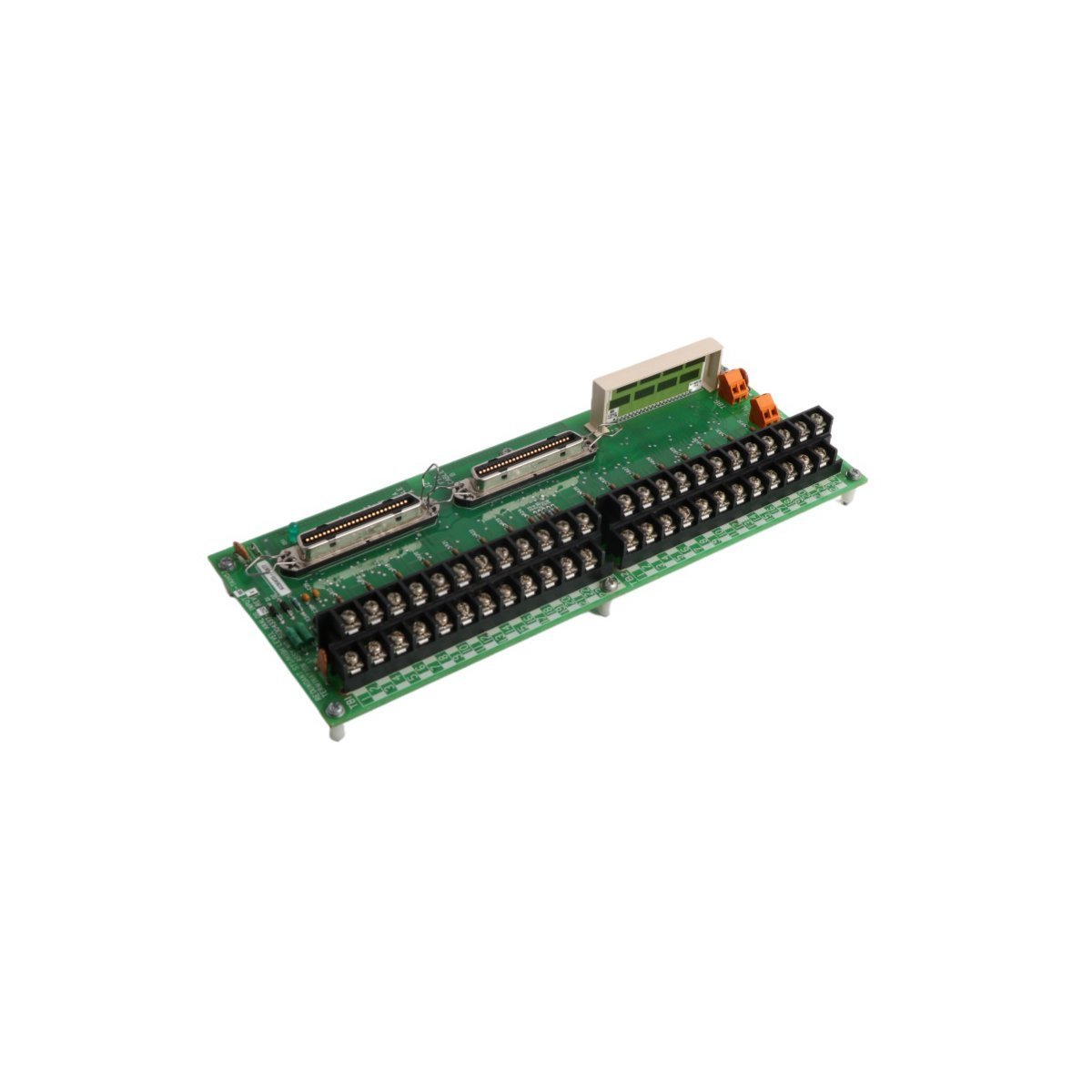
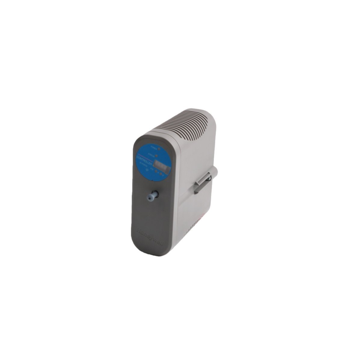
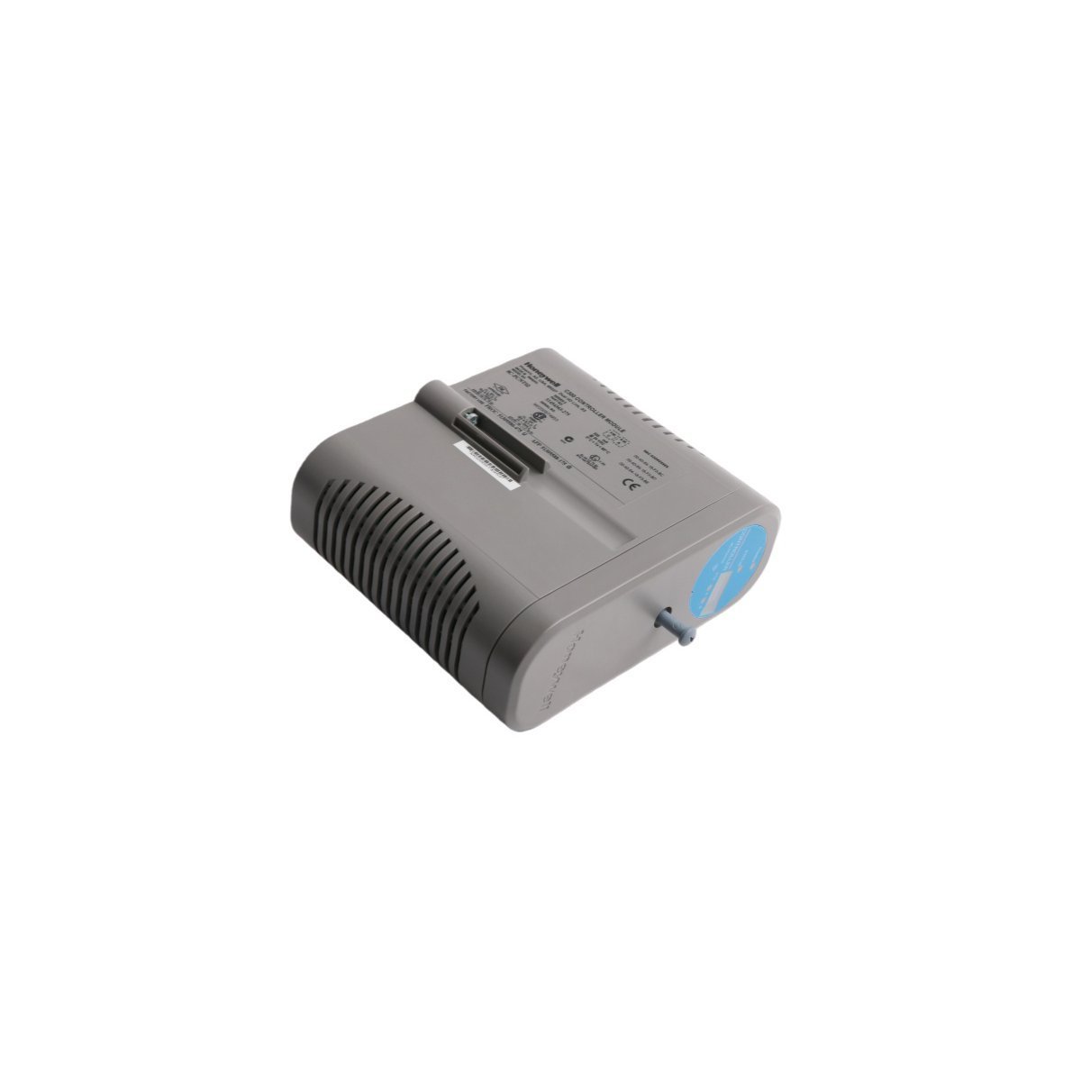
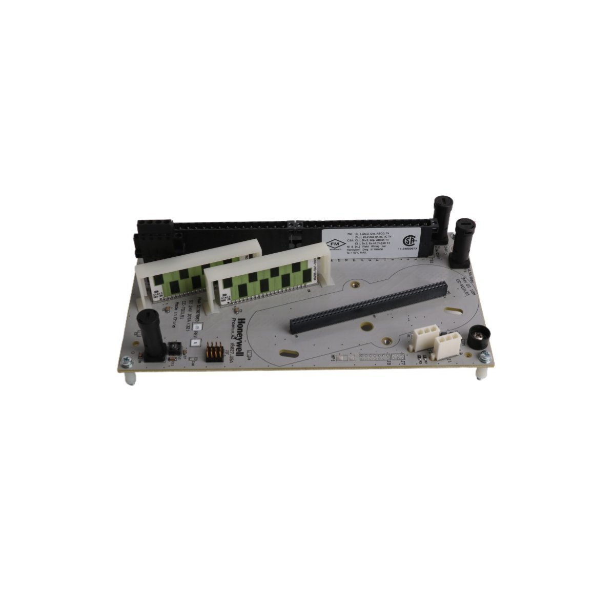
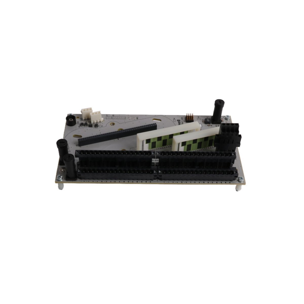
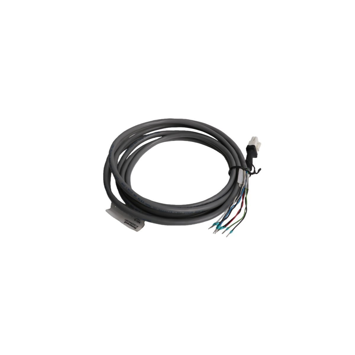
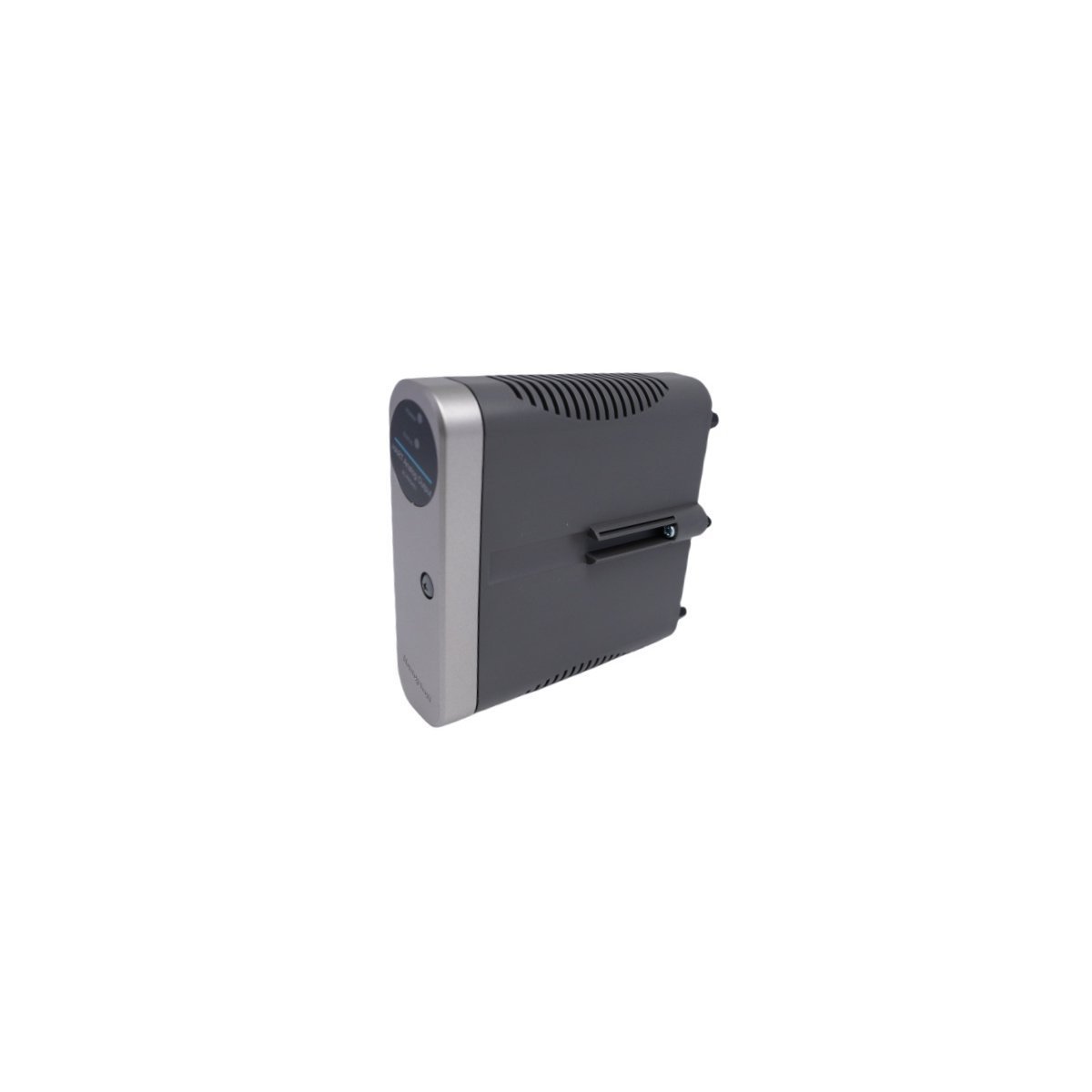
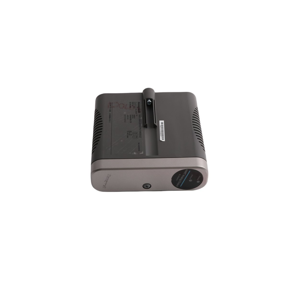
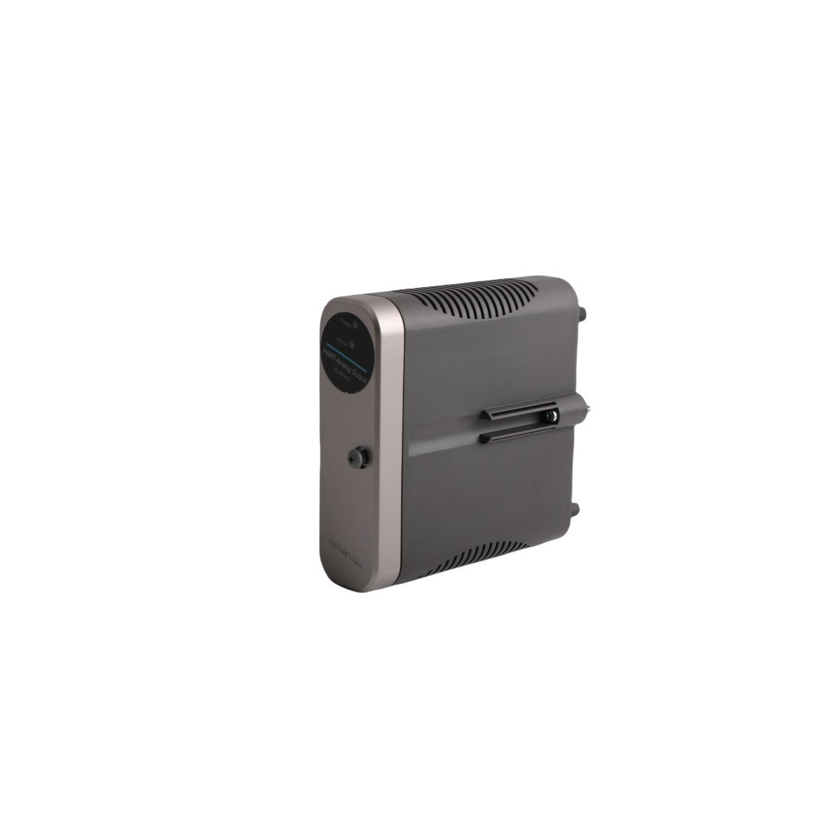
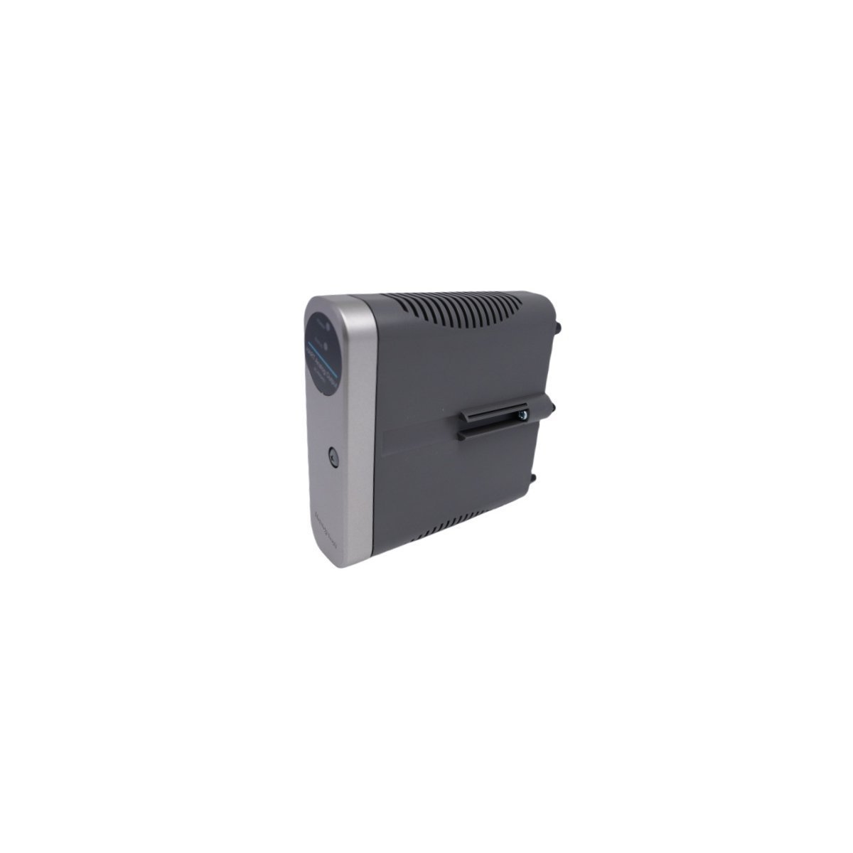
Configured for flexible signal processing in Experion PKS platforms, the Honeywell CC-PUIO01 (CC-PUIO01 Universal I/O Module) provides direct physical and electrical execution of multi-format instrumentation interfaces.
Hardware Specifications
Parameter
Specification
Model
CC-PUIO01
Brand
Honeywell
Origin
USA
Weight
0.6 kg
Dimensions
7.3 x 15.5 x 16.5 cm
Operating Temp
Industrial standard
Power Consumption
Backplane dependent
Product Range
Experion PKS
DCS Signal Conditioning and Isolation
The Honeywell CC-PUIO01 provides channel-to-channel isolation to prevent ground loops and signal interference across the I/O bus. Each channel supports configurable 4-20 mA HART loop protocol connectivity, allowing for bi-directional communication with intelligent field instruments. The module internal circuitry manages cold junction compensation (CJC) for thermocouple inputs, ensuring localized accuracy for temperature measurement loops without requiring external reference modules.
Frequently Asked Questions
Q: Can channels on the CC-PUIO01 be reconfigured while the module is powered?
A: Yes, the module supports channel-level configuration updates via the Experion PKS control builder software without requiring a module power cycle.
Q: What are the limitations regarding hot-swapping this module?
A: The CC-PUIO01 supports hot-swap operations within a redundant I/O carrier; however, ensure the process control strategy is set to a secure state before removal to prevent unintended outputs during the transition.
Q: Is external hardware required for HART communication on this module?
A: No, the HART communication overlay is handled directly by the module firmware, provided the connected field device is HART-compliant.
Field Installation Guidelines
Initially, verify the backplane slot is configured for the Universal I/O module type to prevent potential voltage mismatch errors.
Subsequently, inspect the module connector pins for debris or mechanical deformation before engaging the card into the slot.
Following this, apply consistent pressure to the module faceplate until the locking mechanisms click, ensuring full engagement with the backplane bus connector.
Simultaneously, terminate field wiring to the associated Field Termination Assembly (FTA) according to the project-specific loop diagrams, ensuring all shields are landed on the designated common bus.
Finally, perform a visual inspection of the status LEDs to confirm the module has passed internal self-diagnostics and is communicating with the local controller.
Secure the HONEYWELL 51202942-200 Smart Transmitter Interface Module from our factory-sealed inventory. Brand New, Original Stock, with comprehensive global shipping and technical performance guarantees. Request an immediate technical quote today.
The Honeywell 51307094-100 is a 12-channel dry contact digital output module for the Experion PKS C300 controller.It features programmable debounce, signal filtering, and LED status indicators for each channel. This USA-made Series C module provides precise relay switching for industrial valves, pumps, and HVAC systems.
The Honeywell 51202341-112 is a Series-C I/O Link Power Module designed for Experion PKS systems. It provides stable power and high-speed signal adaptation for C300 controllers and I/O links. This USA-made, 0.4kg module features a robust design to ensure reliable data transmission in mission-critical DCS environments.
The Honeywell 51198651-100 (SPS5785) is a high-performance power supply module for the Experion PKS DCS. Weighing 5.2kg, this brand-new unit provides regulated, stable DC power to controllers and I/O modules, ensuring maximum system uptime in critical industrial environments.
The Honeywell 8C-TPOXA1 51307153-175 is a Series 8 Profibus DP Gateway IOTA.It enables 12 Mbps communication and 64-point I/O management for Experion PKS C300 controllers in industrial process environments.
The Honeywell 8C-IP0102 51454362-275 is an Experion Series 8 Profibus Gateway.It supports DP Master Class-2 functionality and DPV1 messaging for seamless integration of field devices into C300 control systems.
The Honeywell 8C-PDIL51 (51454359-175) is a 24VDC Digital Input Module for Experion PKS Series C systems. This 0.3 kg module provides high-density discrete signal acquisition and real-time diagnostics for industrial DCS applications.
The Honeywell 8C-PAIN01 (51454356-175) is a Series C Analog Input Module for the Experion PKS system. This 0.3 kg unit provides high-accuracy data acquisition and advanced diagnostics for industrial process control.
The Honeywell 8C-PAOH51 (51454355-175) is a high-density 16-channel Analog Output Module for Series C systems. This 0.3 kg unit provides precise actuation and advanced diagnostics for Experion PKS environments.
The Honeywell 51202921-300 is a high-precision Servo Interface Module for Experion PKS systems. It provides robust signal marshalling and barrier protection for critical industrial motion control and DCS applications.
We are committed to protecting your privacy. The information collected here is strictly used to provide the requested quotes, technical support, and relevant industrial automation solutions.