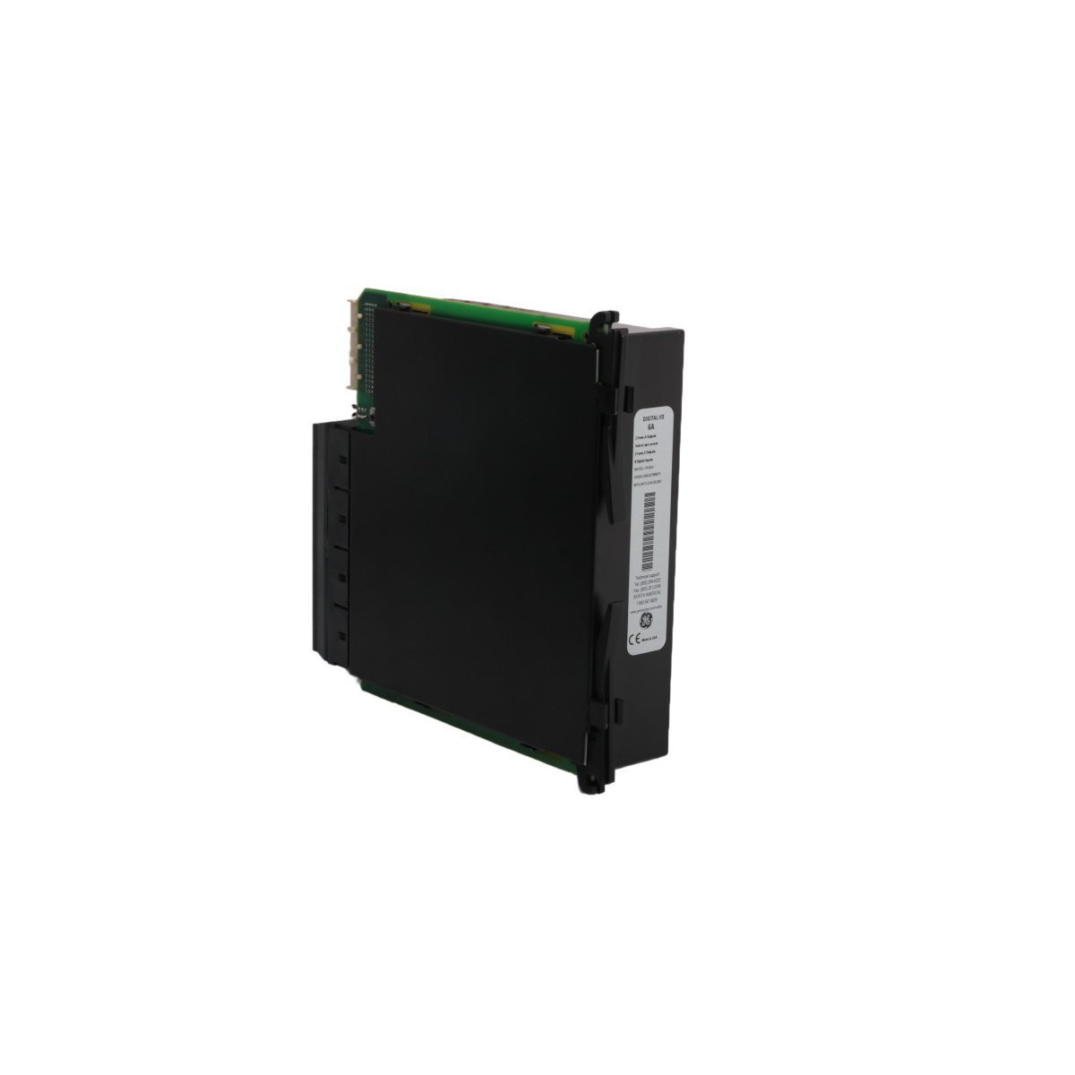
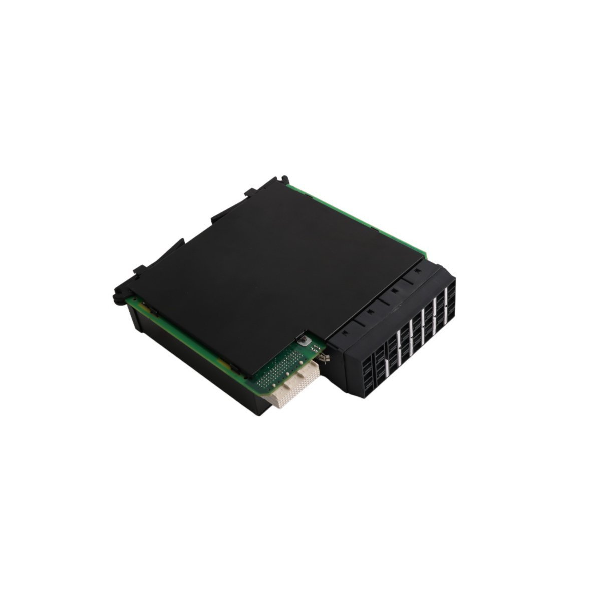
Order the GE IC697MEM717 Expansion Memory Module for Series 90-70 PLCs. Brand New, Original Stock, complete with global shipping options. Expand your industrial application runtime—Request an official quote now.
The GE IC697MEM717, also cataloged as the IC697MEM717 Expansion Memory Module, operates as a dedicated hardware component for memory resource scaling within Series 90-70 PLC platforms. The module interfaces via the local backplane bus to allocate a minimum of 64 KB of supplemental storage space for execution code, configuration registers, and industrial application logic parameters.
Hardware Specifications
Parameter
Specification
Model
IC697MEM717
Brand
GE
Origin
USA
Weight
0.48 kg
Dimensions
29.2 cm x 21.3 cm x 4.0 cm
Operating Temp
0 to 60 deg C
Power Consumption
5 VDC from backplane bus
Module Type
Expansion Memory Module
System
PLC (Series 90-70)
HS CODE
8537101190
Discontinued on
Active
Memory Capacity
64 KB
Industrial Control & Drives (PLC/DCS/Drives)
This GE expansion memory module mounts directly into the standard Series 90-70 rack system to establish high-speed backplane bus communication velocity. The physical circuit architecture interfaces with the primary central processing unit to expand the local program data space and facilitate complex instruction routine processing. The layout is optimized for firmware flash compatibility, preventing data parity errors or transfer latency while executing deterministic automation profiles across local networks.
Frequently Asked Questions
Q: Does the IC697MEM717 module support hot-swapping while the PLC rack is powered?
A: No. Power to the Series 90-70 backplane must be completely isolated before inserting or removing the memory expansion hardware to prevent component damage or register corruption.
Q: How does the processor recognize the supplemental 64 KB capacity?
A: Configuration must be completed within the standard programming software interface to declare the exact expansion slot and align the memory map addressing boundaries.
Field Installation Guidelines
Turn off all main and auxiliary power supplies feeding the PLC rack prior to sliding the module into the designated slot.
Ensure the module aligns precisely with the upper and lower plastic guides within the Series 90-70 chassis before applying seating pressure.
Push the module firmly into the backplane connectors until the faceplate latch engages securely to maintain grounding continuity.
Observe standard electrostatic discharge (ESD) precautions, including using a grounded wrist strap, when handling the internal circuit assemblies.
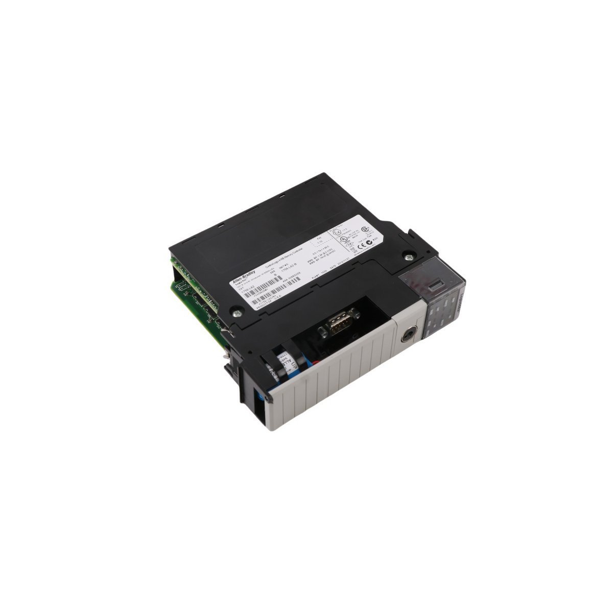
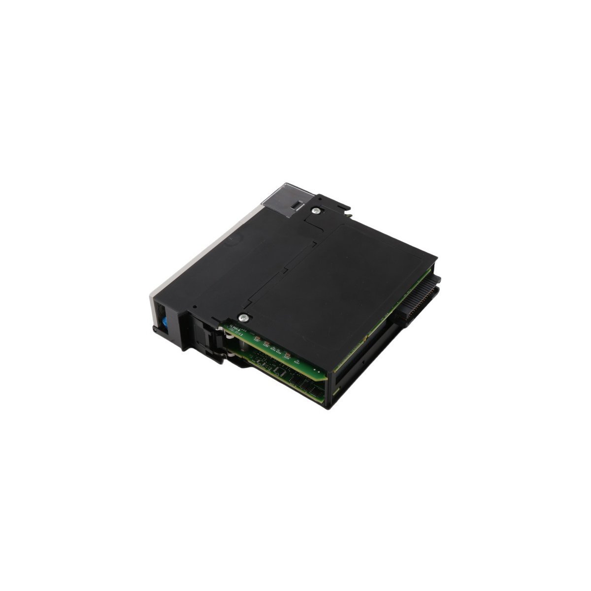
The Allen-Bradley 1756-L62S is a premium GuardLogix 5562S safety processor. Brand New factory-sealed components are available now with prompt Global Shipping. Replace your critical PLC controller units and ensure reliable safety integrity loop execution immediately.
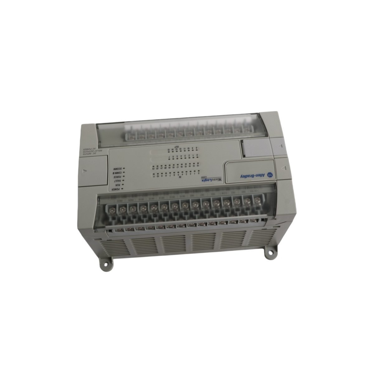
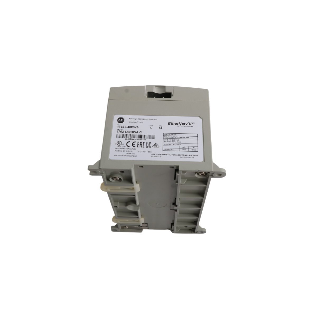
The Allen-Bradley 1762-L40BWA is a 40-point MicroLogix 1200 controller featuring 24V DC inputs and 16 relay outputs. Powered by 120/240V AC, this compact PLC supports high-speed counters and flexible RS-232 communications, making it a reliable solution for sophisticated machine control and industrial automation projects.
The Allen-Bradley 1766-L32BXBA is a MicroLogix 1400 PLC featuring 32 digital I/O points and 6 analog channels. It provides integrated Ethernet/IP, RS-232, and RS-485 ports for flexible networking, making it an ideal 24V DC control solution for complex industrial machinery.
The Emerson 1C31222G01 (5A26458G05) is a high-performance Relay Output Base for Ovation and Fisher PLC systems. This 1.66kg module provides reliable discrete control and electrical isolation for critical DCS applications.
The Emerson KJ1501X1-BC2 (12P2186X042) is a compact, high-performance system power module for DeltaV and Ovation DCS. This 0.18kg VE5002 model provides regulated DC power and integrated diagnostics for critical industrial automation systems.
The Emerson 1C31122G01 is a 16-channel digital output electronics module for Ovation DCS. It provides high-speed discrete signal control for industrial valves, relays, and power system actuators.
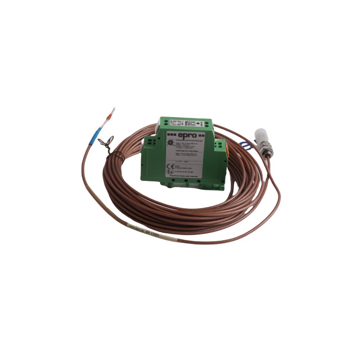
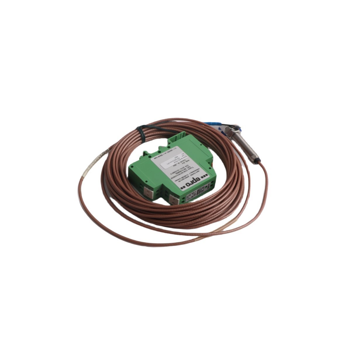
The Emerson PR6423/103-141 CON041 is a high-precision epro eddy current sensor for vibration and displacement monitoring. It offers non-contact measurement for turbines and compressors in harsh environments. This rugged sensor ensures reliable real-time machinery protection and diagnostic accuracy.
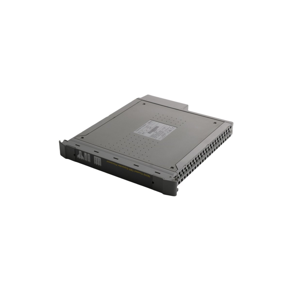
The ICS Triplex T8310 is a TMR Expander Processor for the Trusted system. It features dual ARM Cortex-A9 processors and 2GB RAM to provide fault-tolerant chassis expansion for critical safety applications.
The GE Multilin UR9AH is a high-speed 32-bit CPU module designed for the UR Series protective relays. It features SIL 3 safety certification, IEC 61850 compliance, and supports 64 digital inputs and 32 outputs for advanced industrial automation and power system protection.
The Allen-Bradley 1785-ME16 is a 16K Word EEPROM memory module designed for the PLC-5 series.It provides non-volatile program backup and features a hardware write-protection jumper to ensure data integrity and automatic system recovery for enhanced and Ethernet PLC-5 processors.
The Emerson Epro PR9268/201-100 is a professional-grade electrodynamic velocity sensor for industrial vibration monitoring. This 1.22kg ruggedized module integrates seamlessly with Emerson DCS systems to provide accurate, real-time machinery health data, ensuring maximum uptime and proactive maintenance for rotating equipment.
The Allen-Bradley 1756-L61S is a SIL 3 rated GuardLogix Safety CPU featuring 2 MB of user memory and conformal coating for harsh environments. Designed for the ControlLogix platform, it provides integrated safety and standard control, ensuring high-speed logic execution and robust data acquisition for complex industrial automation systems.
We are committed to protecting your privacy. The information collected here is strictly used to provide the requested quotes, technical support, and relevant industrial automation solutions.