
21000-34-10-20-058-04-02 | Bently Nevada | Proximity Probe HousingAssemblies
Technical Overview
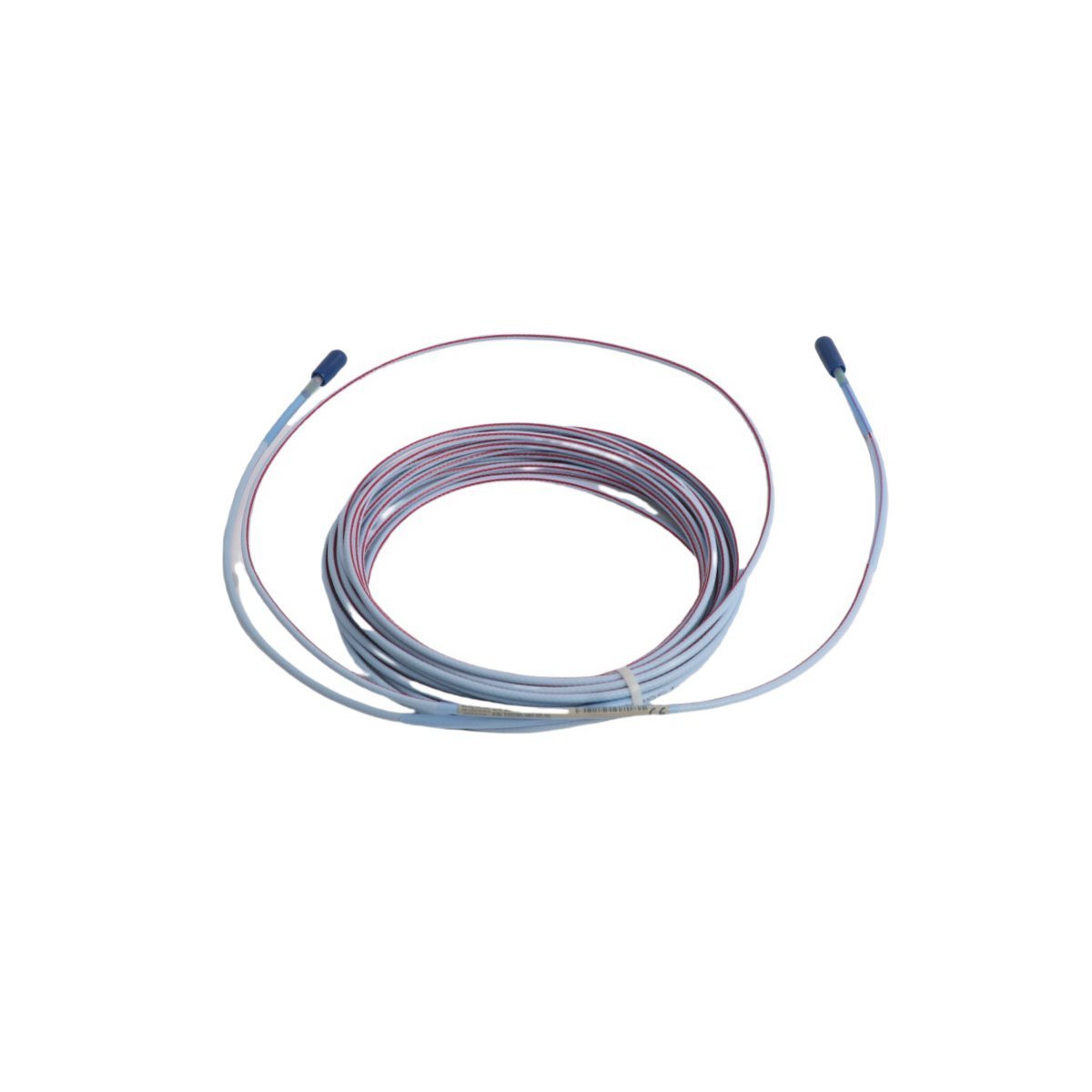
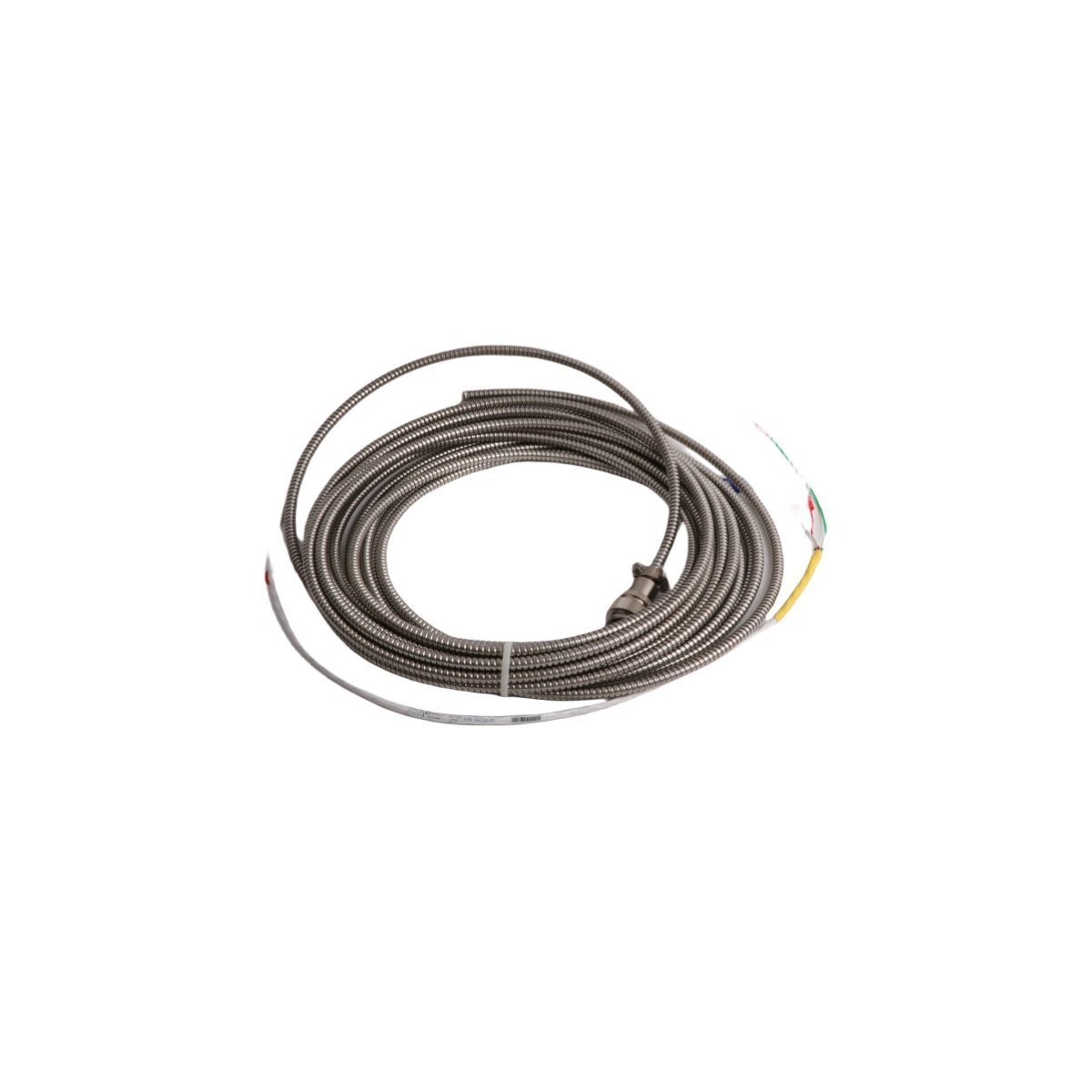
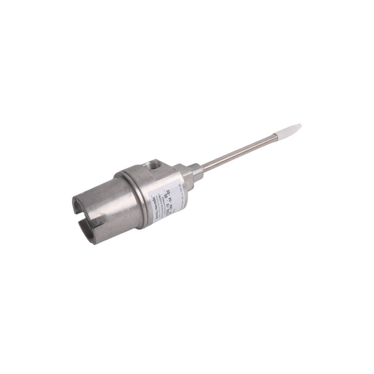
The Bently Nevada 21000-34-10-20-058-04-02 is a rigid proximity probe housing assembly designed for the external mounting of proximity probes on machinery casings. Its primary function is to provide a secure, environmentally sealed, and mechanically protected housing for a non-contacting eddy current proximity probe. This specific assembly, constructed from 304 Stainless Steel, ensures robust performance in corrosive industrial environments. It positions a 3300 XL 8 mm probe at a fixed distance from the mounting surface, defined by its 3.4-inch standoff dimension. When integrated into a Bently Nevada 3500 Machinery Protection System, the probe within the 21000-34-10-20-058-04-02 housing measures shaft vibration and position. The probe transmits a high-frequency RF signal, which is modulated by the gap to the conductive target. This signal is then demodulated by a Proximitor sensor, producing a DC voltage proportional to the gap. This voltage is processed by a 3500 monitor module (e.g., 3500/42M) to provide critical data for machinery diagnostics and protection, such as radial vibration, axial thrust position, and speed.
Detailed Specifications
| Parameter | Specification |
|---|---|
| Manufacturer | Bently Nevada |
| Part Number | 21000-34-10-20-058-04-02 |
| Product Type | Proximity Probe Housing Assembly |
| Condition | Brand New |
| Warranty | 12 Months |
| Material of Construction | 304 Stainless Steel |
| Mounting Thread Option | 3/4 - 14 NPT |
| Standoff Adapter Dimension (A) | 3.4 in (86 mm) |
| Housing Length (C) | 5.8 in (147 mm) |
| Included Probe | 3300 XL 8 mm Proximity Probe |
| Probe Cable Length (B) | 2.0 m (6.6 ft) |
| Operating Temperature Range | -34 °C to +177 °C (-29 °F to +350 °F), limited by probe/cable specifications |
Operational Capabilities
In Oil & Gas and Power Generation applications, the 21000-34-10-20-058-04-02 housing assembly demonstrates high reliability in demanding operational conditions. Its 304 Stainless Steel construction provides excellent resistance to corrosion from process fluids, steam, and harsh atmospheric contaminants common in these industries. The rigid design ensures the probe's measurement gap remains stable, preventing measurement drift and false alarms, which is critical for the protection of high-speed turbomachinery. The 3/4 - 14 NPT mounting thread, when installed correctly with appropriate sealant, provides a secure, pressure-tight seal against machine casing pressures. This configuration is rated for hazardous area classifications when used with appropriate intrinsic safety barriers. The assembly's design minimizes susceptibility to mechanical shock and vibration, ensuring the integrity of the measurement signal path from the probe to the monitoring system for long-term, uninterrupted machinery protection.
Applications
- Power generation turbines and generators
- Oil & gas compressors and pumps
- Industrial rotating machinery monitoring
- Predictive maintenance systems
- Process automation
Technical FAQ
Q: What systems is the 21000-34-10-20-058-04-02 compatible with?
A: The 21000-34-10-20-058-04-02 contains a 3300 XL 8 mm probe. This probe is a component of a complete transducer system that must also include a 3300 XL extension cable and a 3300 XL Proximitor Sensor. The complete transducer system is directly compatible with Bently Nevada monitoring systems, including the 3500 Series, 3300 Series, and the Orbit 60 Series. It provides a standard analog voltage signal (typically 2 to 18 Vdc or -2 to -18 Vdc) to the monitor's input module for processing.
Q: What are the installation requirements?
A: Installation requires a machined mounting boss on the machine case with a 3/4 - 14 NPT tapped hole. The surface of the boss must be perpendicular to the shaft centerline to ensure accurate measurement. Use an appropriate thread sealant (e.g., PTFE tape or liquid sealant rated for the process temperature and fluid) on the NPT threads to create a secure seal and prevent loosening. The assembly should be tightened to the specified torque value. After mechanical installation, the probe gap must be set by adjusting the probe within the housing to achieve the desired DC voltage, typically the center of its linear range (e.g., -10 Vdc for a standard 80 mil / 2 mm range), before locking it in place.