


Sale!
Honeywell CV-DME520-ESD PlantCruise Media Kit
Genuine Honeywell CV-DME520-ESD Electronic Software Delivery media kit for PlantCruise and Experion LX architectures. Complete installation guidelines and capacity parameters.
The 330881-16-00-395-06-02 Bently Nevada PROXPAC XL Proximity Transducer is available in Brand New condition with Original Stock tracking and Global Shipping. Secure industrial TSI components immediately.
The Bently Nevada 330881-16-00-395-06-02, also cataloged as the 330881-16-00-395-06-02 PROXPAC XL Proximity Transducer, serves as the primary 330881 PROXPAC XL Proximity Transducer utilized to execute non-contacting shaft displacement and vibration measurements across TSI platforms. The integrated sensor assembly converts mechanical micro-gaps into linear electrical potential differences via high-frequency eddy-current generation, facilitating real-time monitoring of rotor dynamics in high-speed machinery.
| Parameter | Specification |
|---|---|
| Model | 330881-16-00-395-06-02 |
| Brand | Bently Nevada |
| Origin | USA |
| Weight | 0.06 kg |
| Dimensions | 1.8 x 1.6 x 123 cm |
| Operating Temp | -35 to +85 deg C |
| Power Consumption | 0.8 W maximum |
| Module Type | PROXPAC XL Proximity Transducer |
| Series | 3300 System / 3300 XL Series |
| Supply Voltage | -17.5 VDC to -26 VDC |
| Thread Specification | 3/4-14 NPT mounting thread |
| Penetration Depth | 175 mm |
| HS Code | 8537101190 |
The hardware features precise eddy-current probe scaling calibrated for standard AISI 4140 steel target materials. To guarantee nominal sensor linearity, the installation loop relies on gap voltage validation target levels of -10 VDC, corresponding to the midpoint of the calibrated linear range. The underlying analog front-end incorporates passive cross-talk suppression filters, eliminating high-frequency phase interactions when multiple proximity sensor tips operate in close structural proximity along the same machine casing plane.
Q: What is the significance of the gap voltage validation value for this transducer?
A: The gap voltage must read approximately -10 VDC when measured at the ProxPac terminal outputs under static mechanical conditions. This indicates the probe tip is positioned exactly at the center of its linear electrical displacement curve relative to the shaft surface.
Q: Does this transducer interface directly with standard 3500 system monitor modules?
A: Yes. The signal output matches the input impedance and scale requirements of standard 3300 or 3500 Proximitor monitor cards when supplied with the specified negative voltage rails.
Q: Is hot-swapping terminal connections permitted while the system is monitoring?
A: Disconnecting the field wiring terminal block under power will trigger a NOT OK alarm condition on the associated monitor card, but it will not damage the internal circuitry of the transducer module.
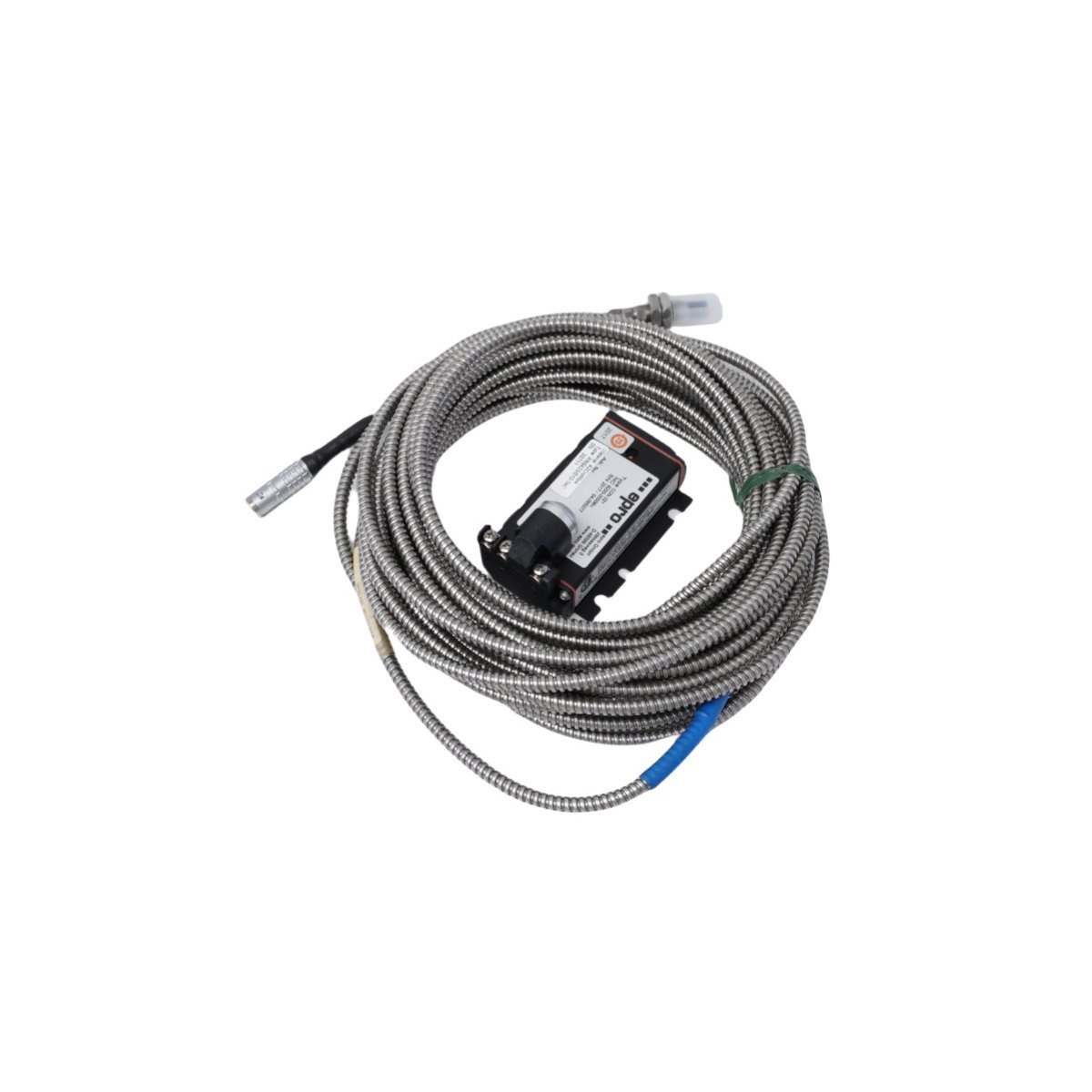
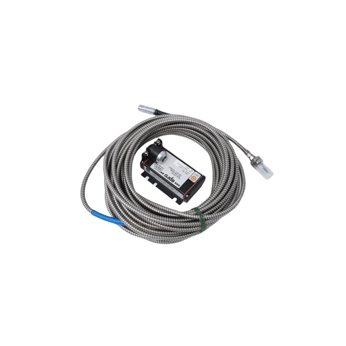
The Emerson EPRO PR6423/010-000 CON021 Eddy Current Signal Converter delivers ultra-precise, non-contact displacement and vibration measurements for critical rotating machinery. Featuring an 8 mm tip diameter, a rugged stainless steel housing, and advanced internal temperature compensation, it provides reliable, continuous asset protection and seamless DCS integration in harsh, high-pressure industrial environments.
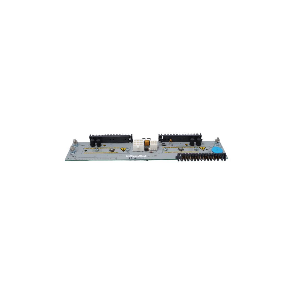
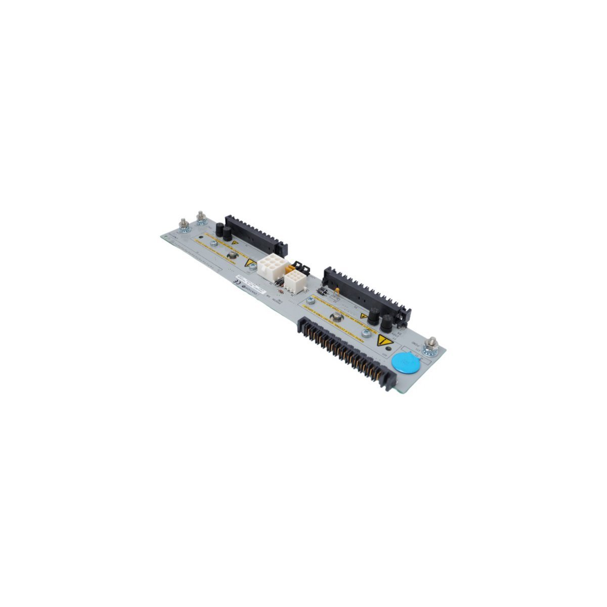
The Emerson Ovation 1P00028G01 Remote Node Transition Panel provides robust signal routing and high-integrity electrical isolation for legacy Ovation Distributed Control Systems (DCS). Operating at 220V AC across an ultra-wide temperature range of -40°C to +85°C, this compact transition panel eliminates field line noise and ensures reliable, deterministic peer-to-peer communication between remote I/O nodes and central controllers in demanding industrial environments.


The Bently Nevada 89477-30 is a specialized interconnect cable engineered for the 3500 Machinery Protection System. Its primary function is to establish a high-integrity communication link between a 3500/42M Proximitor/Seismic Monitor and its corresponding rear-mounted I/O module. The cable transmits raw, unamplified dynamic vibration and axial position signals from the I/O module's input terminals to the monitor's processing circuitry. It concurrently carries the -24 Vdc power from the monitor to the I/O module, which in turn powers the connected Proximitor probes. The 89477-30 is constructed as a multi-conductor, shielded assembly to ensure high signal-to-noise ratio (SNR) and protect the low-amplitude transducer signals from electromagnetic interference (EMI) and radio-frequency interference (RFI) prevalent in industrial environments. This robust shielding is critical for the accuracy of sub-mil (micrometer) level measurements required for effective machinery diagnostics and protection. The cable's specific length and keyed connectors ensure proper installation and signal path integrity within the 3500 rack architecture.
| Parameter | Specification |
|---|---|
| Manufacturer | Bently Nevada |
| Part Number | 89477-30 |
| Product Type | Interconnect Cable |
| Condition | Brand New |
| Warranty | 12 Months |
| Cable Length | 3.0 meters (9.8 feet) |
| Connector Type | Multi-pin, keyed D-subminiature with jackscrew locking mechanisms |
| System Compatibility | Bently Nevada 3500/42M Proximitor/Seismic Monitor and associated I/O modules |
| Cable Construction | Multi-conductor, 22 AWG, with overall foil and/or braid shielding |
| Operating Temperature | -30°C to +65°C (-22°F to +149°F) |
| Signal Type | Transmits dynamic transducer signals (vibration, position) and DC power |
| Application Environment | For internal use within 3500 system racks; not rated for field installation |
In Oil & Gas and Power Generation applications, the 89477-30 interconnect cable demonstrates high reliability essential for continuous machinery protection. Its performance is defined by its ability to maintain signal integrity in environments with significant electrical noise and mechanical vibration. The cable's robust construction, featuring secure locking connectors and comprehensive shielding, prevents signal degradation and intermittent connections, which are potential sources of false trips or missed alarms in a protection system. The specified operating temperature range of -30°C to +65°C ensures stable performance within control cabinets and rack rooms that experience thermal cycling. The reliability of the 89477-30 is a critical factor in the overall safety integrity level (SIL) rating of the 3500 system, as it provides the foundational data link for detecting incipient faults such as bearing wear, imbalance, and shaft cracks in critical rotating assets.
Q: What systems is the 89477-30 compatible with?
A: The 89477-30 interconnect cable is designed exclusively for the Bently Nevada 3500 Machinery Protection System. It specifically facilitates the connection between a 3500/42M Proximitor/Seismic Monitor and its corresponding I/O module (e.g., 3500/42M I/O with Internal Terminations). It is not designed or validated for use with other Bently Nevada system series (such as 3300) or any third-party monitoring equipment.
Q: What are the installation requirements?
A: Installation must be performed by a qualified instrumentation technician familiar with the 3500 system. The cable is to be routed within the 3500 rack, ensuring it is not pinched, kinked, or subjected to tension. Adhere to a minimum bend radius of 10 times the cable's outer diameter. The keyed connectors prevent incorrect mating; do not apply force if resistance is met. After seating the connectors, fully tighten the jackscrews to prevent disconnection from cabinet vibration. Route the 89477-30 cable away from high-voltage AC power wiring to further mitigate any risk of noise induction.


The Bently Nevada 330104-00-14-10-11-00 Proximity Probes is a genuine industrial component.
| Condition | New |
We are committed to protecting your privacy. The information collected here is strictly used to provide the requested quotes, technical support, and relevant industrial automation solutions.