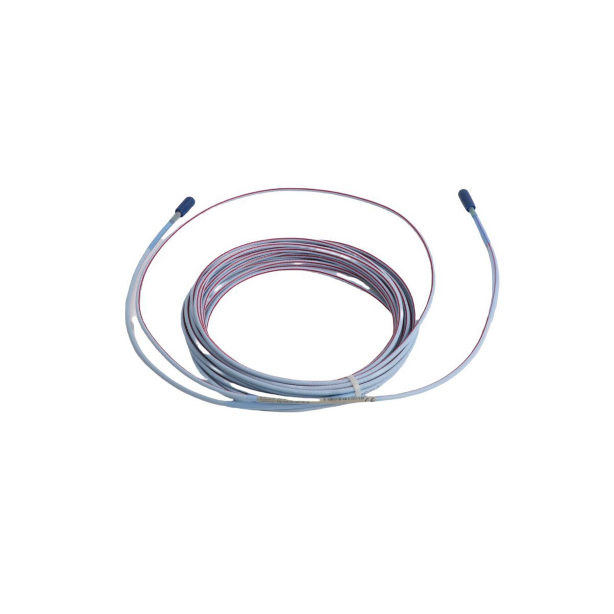
Purchase the genuine Bently Nevada 21747-045-01 4.5-meter armored Proximitor probe extension cable from our factory-certified component stock. Complete with stainless steel armor, verified impedance matching, and fast global shipping.
The Bently Nevada 21747-045-01, also cataloged as the 21747 Proximitor Probe Extension Cable, operates as a dedicated hardware component for high-frequency signal transmission within Bently Nevada TSI machinery protection platforms. The physical coaxial assembly connects non-contacting eddy-current proximity probes to external Proximitor sensor modules, establishing a continuous tuned impedance loop. By extending physical boundaries up to a factory-calibrated length, it preserves raw electrical displacement metrics generated near critical rotating machinery elements.
Hardware Specifications
Parameter
Specification
Model
21747-045-01
Brand
Bently Nevada
Origin
USA
Weight
0.45 kg
Dimensions
30 x 28 x 2 cm
Operating Temp
-51 to +177 deg C
Power Consumption
Passive physical high-frequency signal link
Module Type
Proximitor Probe Extension Cable
System Platform
TSI (Turbine Supervisory Instrumentation) / 3500 Series
Eddy-Current Probe Scaling and Gap Voltage Validation
The 21747-045-01 assembly possesses precise electrical capacitance and inductance parameters matching specific eddy-current probe scaling configurations. This calibrated matching is critical to achieve correct linear voltage slopes during gap voltage validation steps, targeting a -10 VDC nominal center point on the calibration line. The mechanical armor layer prevents raw measurement attenuation and eliminates physical path degradation from external compression stresses. Furthermore, the specialized outer shield design provides cross-talk suppression between high-density parallel sensor paths traversing hot-oil machine housings and complex rotor dynamics monitoring zones.
Frequently Asked Questions
Q: What parameters do the “045” and “01” suffixes define in this model configuration?
A: The “045” suffix designates a factory-calibrated length of exactly 4.5 meters (177 inches), while the “01” suffix specifies the inclusion of heavy-duty stainless steel protective armor encapsulating the internal coaxial line.
Q: Can this 4.5-meter extension cable be paired with any random length proximity probe?
A: No. The extension cable must be matched with the specific proximity transducer length required by the Proximitor system configuration (typically creating a total loop length of 5.0 meters or 9.0 meters) to maintain tuned circuit impedance calibration.
Q: Is it permissible to shorten or patch this cable in the field if physical damage occurs?
A: No. Cutting or splicing the coaxial line alters the circuit’s total electrical length, capacitance, and impedance, resulting in major calibration drift, corrupted vibration data, and the loss of accurate fault metrics.
Field Installation Guidelines
Minimum Bend Radius Limits: Do not exceed the minimum physical bend radius of 25 mm during path installation. Sharper bends can kink the inner conductor, alter internal capacitance parameters, and damage the protective stainless steel armor.
Connector Isolation and Sealing: Connect the miniature coaxial unions tightly using a factory-certified connector wrench tool. Insulate the exposed connection point completely with self-amalgamating tape or clear heat-shrink sleeves to block ground loops and hot-oil fluid contamination.
Conduit Path Separation: Route the armored cable length through dedicated low-voltage instrumentation trays or conduits. Isolate the signal path from high-voltage motor feeds or variable frequency drive (VFD) lines to suppress electromagnetic noise injection.
Terminal Box Stress Relief: Secure the cable entry points with matching strain-relief glands where the line transitions into terminal boxes, preventing physical tension from damaging the internal miniature terminal connectors.
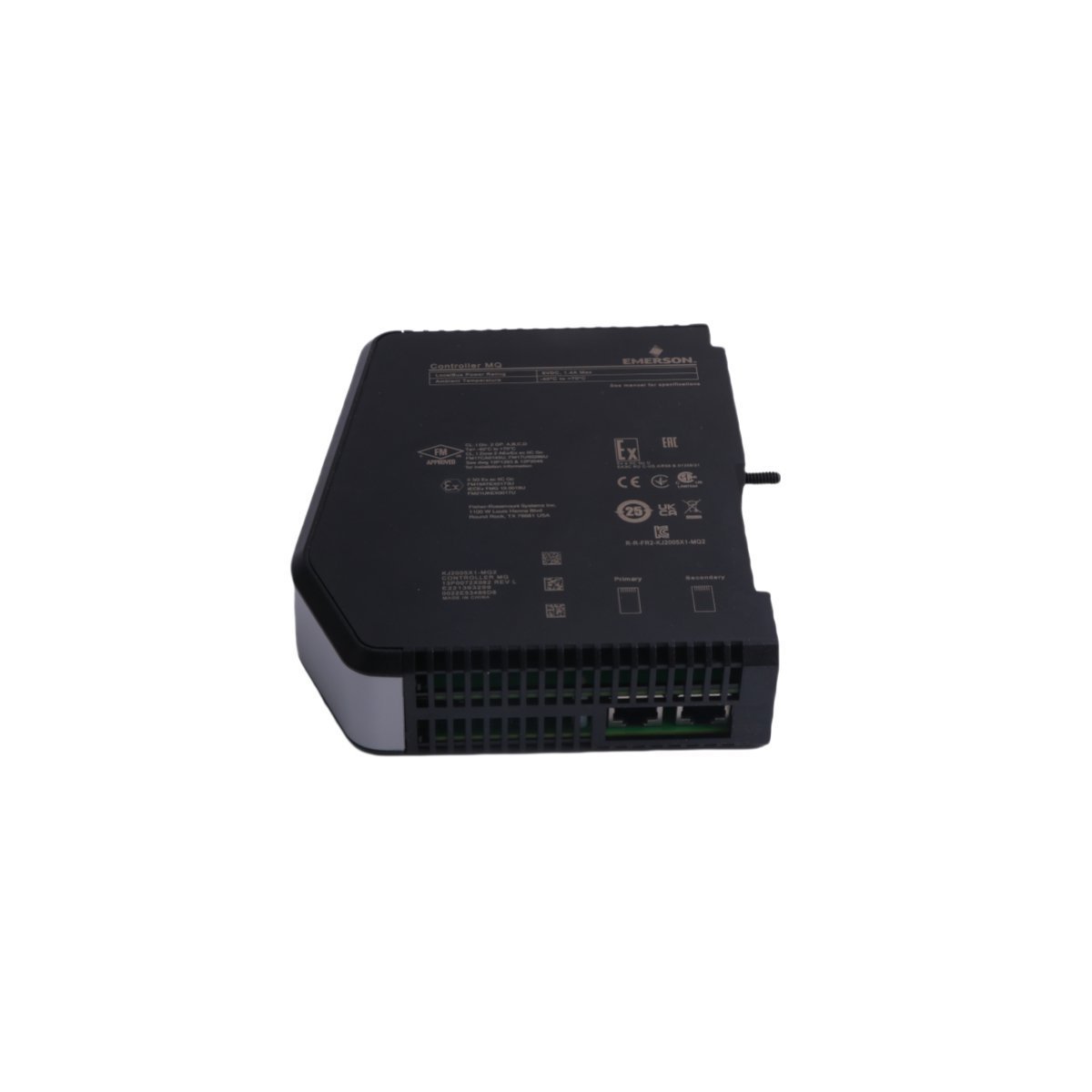
The EMERSON VE3008 KJ2005X1-MQ2 controller module provides real-time control logic for DeltaV DCS architectures. Brand New, original stock, global delivery. Keep your automated processes responsive—Contact us for a quotation.
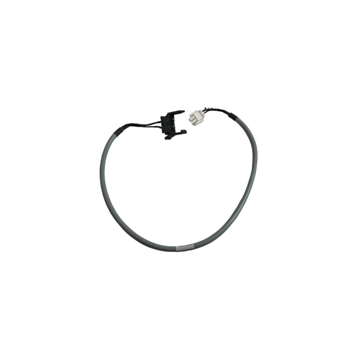
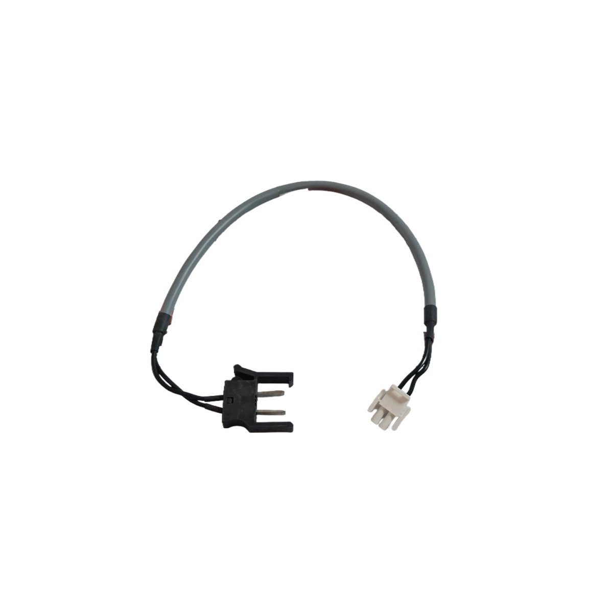
Buy original HONEYWELL FS-PDC-CPSET Safety Manager Power Distribution Cable Assemblies. Comprises 2.5 mm² cross-section copper conductors with robust Mate-N-Lock connectors. Genuine USA factory surplus stock ready for dispatch.
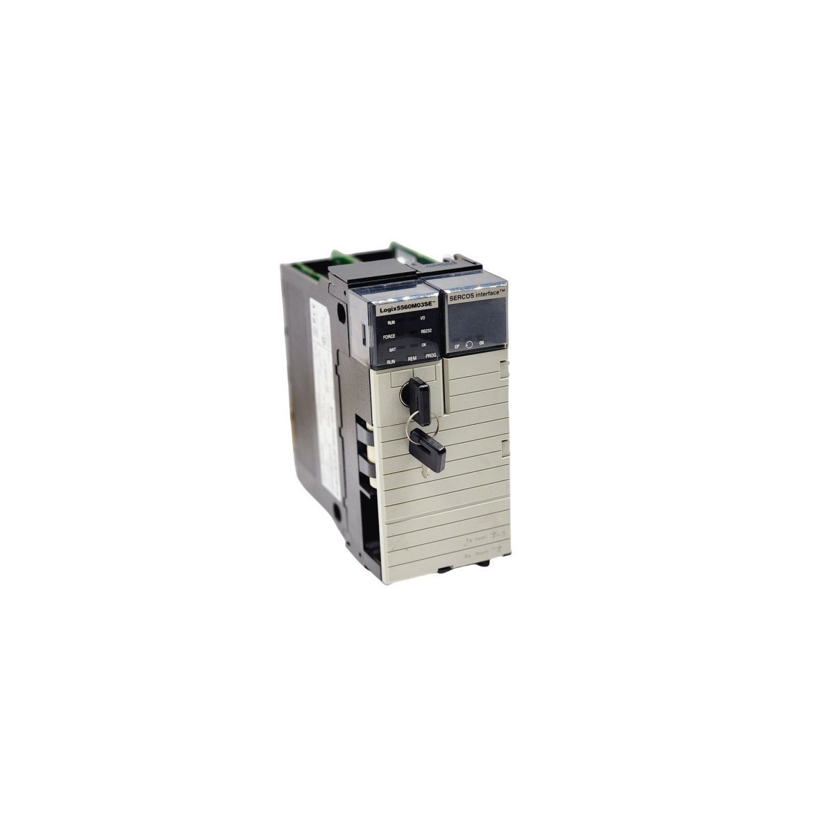
The Allen-Bradley 1756-L60M03SE is a GuardLogix Safety CPU module featuring 750 KB memory and 3-axis SERCOS motion control. This ControlLogix processor supports extensive networking via EtherNet/IP and ControlNet, making it ideal for integrated safety and high-precision motion applications.
The Yokogawa SNT501-13 is a premium Optical ESB Bus Repeater Module designed for long-distance DCS and SIS communication. It supports high-speed 128 Mbps data transfer over fiber optics up to 5 km, providing the EMI immunity and redundancy required for mission-critical industrial automation safety.
The Bently Nevada 31000-16-10-15-030-03-02 is a specialized proximity probe housing designed to physically protect a proximity probe and its integral cable within harsh industrial environments. Its primary function is to provide a secure, environmentally sealed mounting point on rotating machinery for acquiring critical vibration and position data. The housing is constructed from 304 Stainless Steel, offering robust protection against physical impact and corrosion. This specific configuration, 31000-16-10-15-030-03-02, features a 3/4-14 NPT external mounting thread for direct installation into a machine case. Internally, it accommodates a Bently Nevada 3300 XL 8 mm or 3300 5 mm probe, which is positioned by a 1.0-inch stinger (probe sleeve). The housing facilitates the signal path from the probe tip to the Bently Nevada 3500 Monitoring System. The probe, connected via an extension cable to a Proximitor Sensor, generates a high-frequency RF signal. The resulting eddy current field is used to measure the distance to the observed conductive target. The Proximitor Sensor conditions this signal into a calibrated DC voltage proportional to the gap, which is then transmitted to a 3500/42M Proximitor/Seismic Monitor module for analysis, alarming, and machinery protection.
Detailed Specifications
Parameter
Specification
Manufacturer
Bently Nevada
Part Number
31000-16-10-15-030-03-02
Product Type
31000 Proximity Probe Housing
Condition
Brand New
Warranty
12 Months
Housing Material
304 Stainless Steel
Mounting Thread
3/4-14 NPT
Stinger (Probe Sleeve) Length
1.0 inch (25.4 mm)
Probe Compatibility
Bently Nevada 3300 XL 8 mm and 3300 5 mm Proximity Probes
Environmental Sealing
Viton O-ring cable seal included
Operating Temperature Range
-34 °C to +177 °C (-30 °F to +350 °F)
Hazardous Area Suitability
Suitable for Class I, Div 2 / Zone 2 locations when installed per Bently Nevada control drawings and with appropriately certified system components.
Operational Capabilities
In Oil & Gas applications, the 31000-16-10-15-030-03-02 housing provides essential protection for transducers monitoring centrifugal and reciprocating compressors, pumps, and gearboxes. Its 304 Stainless Steel construction and Viton seals ensure long-term integrity in environments containing corrosive elements such as H2S and hydrocarbons, a critical requirement for meeting API 670 standards for machinery protection systems. In Power Generation, this housing is extensively used on steam and gas turbines, exciters, and boiler feed pumps. It maintains measurement accuracy and reliability under conditions of high temperature and vibration, which is fundamental for monitoring shaft radial vibration, axial thrust position, and differential expansion. The passive mechanical design results in a high Mean Time Between Failures (MTBF), contributing to overall plant availability. When properly installed, the housing assembly provides an environmental rating equivalent to NEMA 4X and IP65, preventing ingress of dust, moisture, and process contaminants that could otherwise compromise signal integrity
The Bently Nevada 89477-30 is a specialized interconnect cable engineered for the 3500 Machinery Protection System. Its primary function is to establish a high-integrity communication link between a 3500/42M Proximitor/Seismic Monitor and its corresponding rear-mounted I/O module. The cable transmits raw, unamplified dynamic vibration and axial position signals from the I/O module's input terminals to the monitor's processing circuitry. It concurrently carries the -24 Vdc power from the monitor to the I/O module, which in turn powers the connected Proximitor probes. The 89477-30 is constructed as a multi-conductor, shielded assembly to ensure high signal-to-noise ratio (SNR) and protect the low-amplitude transducer signals from electromagnetic interference (EMI) and radio-frequency interference (RFI) prevalent in industrial environments. This robust shielding is critical for the accuracy of sub-mil (micrometer) level measurements required for effective machinery diagnostics and protection. The cable's specific length and keyed connectors ensure proper installation and signal path integrity within the 3500 rack architecture.
Detailed Specifications
Parameter
Specification
Manufacturer
Bently Nevada
Part Number
89477-30
Product Type
Interconnect Cable
Condition
Brand New
Warranty
12 Months
Cable Length
3.0 meters (9.8 feet)
Connector Type
Multi-pin, keyed D-subminiature with jackscrew locking mechanisms
System Compatibility
Bently Nevada 3500/42M Proximitor/Seismic Monitor and associated I/O modules
Cable Construction
Multi-conductor, 22 AWG, with overall foil and/or braid shielding
Operating Temperature
-30°C to +65°C (-22°F to +149°F)
Signal Type
Transmits dynamic transducer signals (vibration, position) and DC power
Application Environment
For internal use within 3500 system racks; not rated for field installation
Operational Capabilities
In Oil & Gas and Power Generation applications, the 89477-30 interconnect cable demonstrates high reliability essential for continuous machinery protection. Its performance is defined by its ability to maintain signal integrity in environments with significant electrical noise and mechanical vibration. The cable's robust construction, featuring secure locking connectors and comprehensive shielding, prevents signal degradation and intermittent connections, which are potential sources of false trips or missed alarms in a protection system. The specified operating temperature range of -30°C to +65°C ensures stable performance within control cabinets and rack rooms that experience thermal cycling. The reliability of the 89477-30 is a critical factor in the overall safety integrity level (SIL) rating of the 3500 system, as it provides the foundational data link for detecting incipient faults such as bearing wear, imbalance, and shaft cracks in critical rotating assets.
Applications
Power generation turbines and generators
Oil & gas compressors and pumps
Industrial rotating machinery monitoring
Predictive maintenance systems
Process automation
Technical FAQ
Q: What systems is the 89477-30 compatible with?
A: The 89477-30 interconnect cable is designed exclusively for the Bently Nevada 3500 Machinery Protection System. It specifically facilitates the connection between a 3500/42M Proximitor/Seismic Monitor and its corresponding I/O module (e.g., 3500/42M I/O with Internal Terminations). It is not designed or validated for use with other Bently Nevada system series (such as 3300) or any third-party monitoring equipment.
Q: What are the installation requirements?
A: Installation must be performed by a qualified instrumentation technician familiar with the 3500 system. The cable is to be routed within the 3500 rack, ensuring it is not pinched, kinked, or subjected to tension. Adhere to a minimum bend radius of 10 times the cable's outer diameter. The keyed connectors prevent incorrect mating; do not apply force if resistance is met. After seating the connectors, fully tighten the jackscrews to prevent disconnection from cabinet vibration. Route the 89477-30 cable away from high-voltage AC power wiring to further mitigate any risk of noise induction.
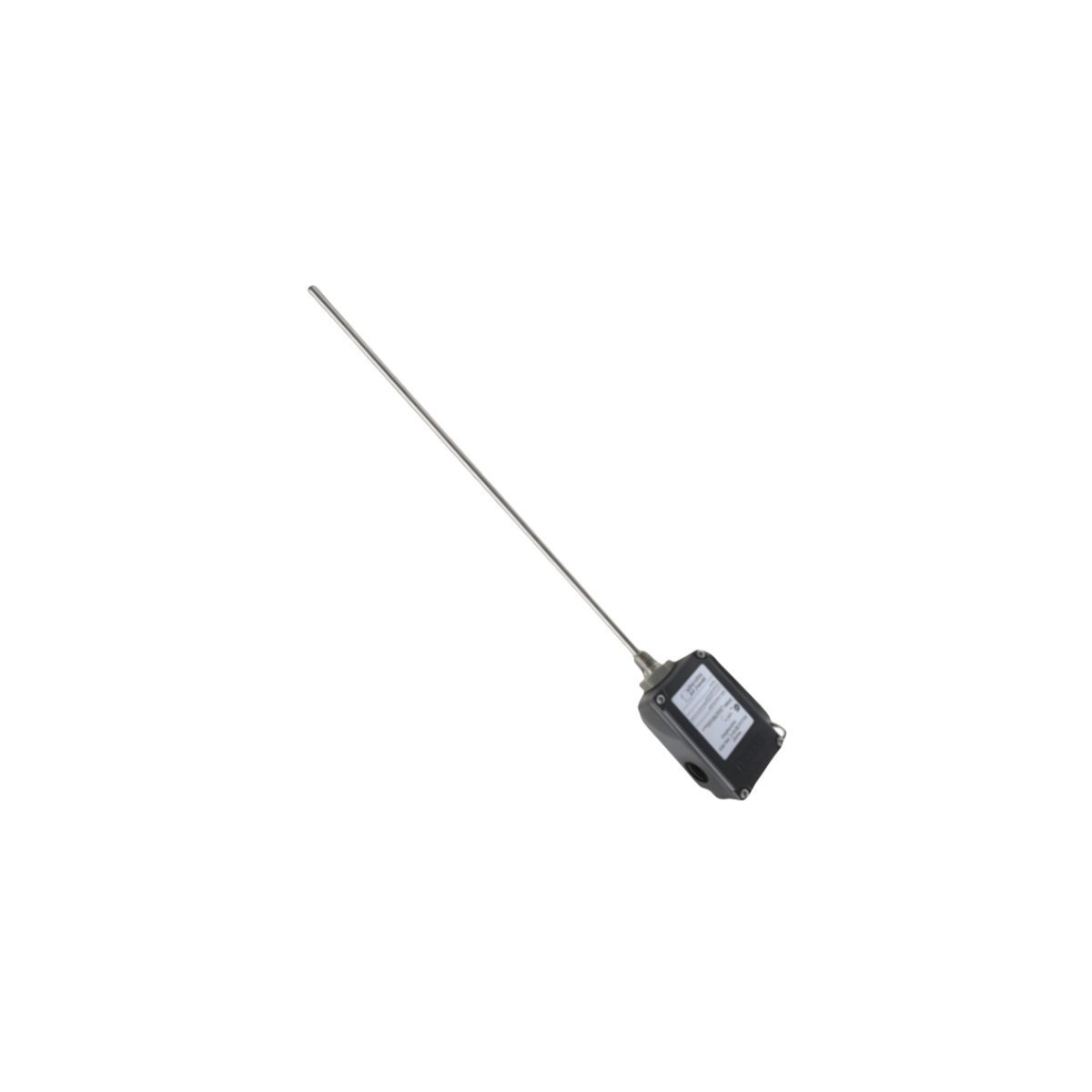
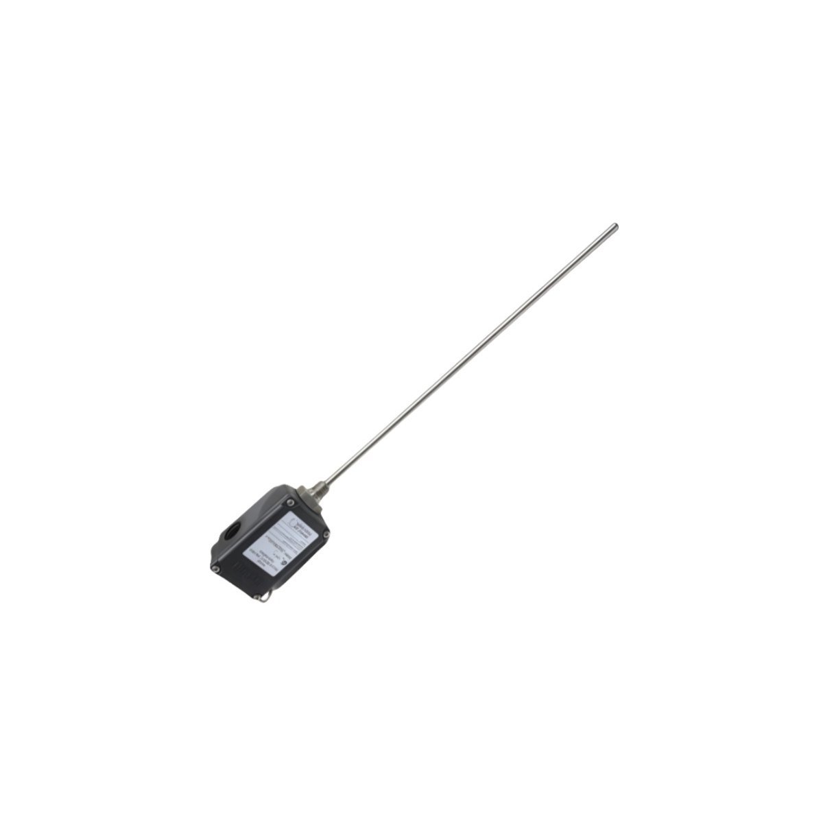
The Bently Nevada 330192-00-28-05-00 is an 8 mm Extended Temperature Range (ETR) proximity probe component of the 3300 XL Proximity Transducer System. Its primary function is to perform non-contact measurement of relative displacement on rotating and reciprocating machinery. The probe operates on an eddy current principle. When paired with a 3300 XL extension cable and Proximitor Sensor, it forms a tuned oscillator circuit that emits a high-frequency radio frequency (RF) field from the probe tip. This field induces eddy currents on the surface of the observed conductive target, typically a machine shaft. The interaction between the RF field and the eddy currents results in a change in the oscillator's amplitude, which is directly proportional to the gap between the probe tip and the target. The Proximitor Sensor demodulates this RF signal into a precise DC voltage. This voltage signal is then transmitted to a monitoring system, such as the Bently Nevada 3500 Series, where it is processed to provide critical measurements including radial vibration, axial position (thrust), and rotational speed (when used in a Keyphasor configuration). The 330192-00-28-05-00 is constructed with a Polyphenylene Sulfide (PPS) tip and a stainless steel body, ensuring robust performance in high-temperature industrial environments.
Detailed Specifications
Parameter
Specification
Manufacturer
Bently Nevada
Part Number
330192-00-28-05-00
Product Type
3300 XL 8 mm ETR Proximity Probes
Condition
Brand New
Warranty
12 Months
Linear Range
2.0 mm (80 mils)
Scale Factor
7.87 V/mm (200 mV/mil) ±5%
Probe Tip Temperature Range
-34 °C to +260 °C (-30 °F to +500 °F)
Total Length
0.5 meters (1.6 feet)
Case Length
2.8 inches (71.1 mm)
Connector Type
Miniature coaxial ClickLoc connector, gold-plated
Probe Tip Material
Polyphenylene Sulfide (PPS)
Operational Capabilities
The 330192-00-28-05-00 probe is engineered for high-reliability machine protection and condition monitoring in demanding industrial sectors. In Oil & Gas applications, its ETR specification (up to +260 °C) allows for installation on high-temperature machinery such as gas turbines, steam turbines, and centrifugal compressors, where probes are often located near hot casings or in high-temperature bearing housings. In Power Generation, it provides essential rotor dynamics data for turbine-generator sets, ensuring safe operation within design limits. The 3300 XL system, including the 330192-00-28-05-00 probe, is designed for high immunity to radio frequency interference (RFI/EMI), a common issue in industrial plants. Its robust construction with an AISI 304 stainless steel case provides excellent resistance to corrosion from hydrocarbons and other process chemicals. The system's stability and repeatability are critical for API 670 compliant machinery protection systems, providing accurate data for automatic shutdown logic and predictive maintenance analysis.
Applications
Power generation turbines and generators
Oil & gas compressors and pumps
Industrial rotating machinery monitoring
Predictive maintenance systems
Process automation
Technical FAQ
Q: What systems is the 330192-00-28-05-00 compatible with?
A: The 330192-00-28-05-00 probe must be used as part of a complete, electrically matched 3300 XL 8 mm transducer system. This system includes a 3300 XL Proximitor Sensor (e.g., P/N 330180-XXXX-XX) and a
The Allen-Bradley MPL-B4560F-SJ72AA is a 460V AC low-inertia servo motor from the Kinetix MP-Series.It features a 3,000 RPM rated speed, a high-resolution optical encoder, and a 130mm frame.Designed for high-speed industrial motion, this brushless motor includes rotatable SpeedTec connectors and a keyed shaft for precise, dynamic automation control.
The Allen-Bradley 2094-BL10S is an all-in-one Line Interface Module for Kinetix 6000 systems. It integrates an EMI filter, circuit breaker, and contactor into a 10A unit, providing safe and filtered 400V-class power distribution
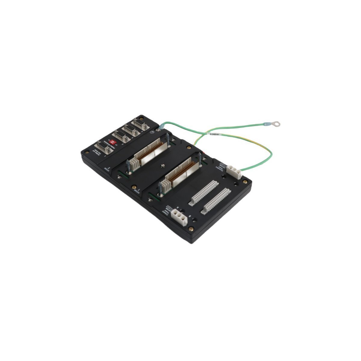
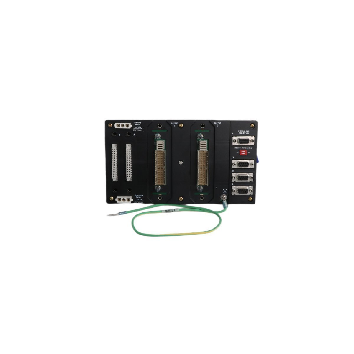
The Foxboro RH924YF is a high-performance DIN-rail mounted baseplate designed for FCP280 processors.This modular unit supports redundant power and high-speed communication, providing a stable and scalable infrastructure for the I/A Series and EcoStruxure DCS.
The Bently Nevada 21000-16-10-15-075-03-02 is a genuine industrial component designed for critical automation systems. This high-quality product delivers reliable performance in demanding industrial environments.
Detailed Specifications
Parameter
Specification
Manufacturer
Bently Nevada
Part Number
21000-16-10-15-075-03-02
Condition
Brand New
Warranty
12 Months
Applications
Industrial automation systems
Process control applications
Manufacturing equipment
Power generation systems
Technical FAQ
Q: Is this a genuine Bently Nevada product?
A: Yes, this is a 100% genuine product with full manufacturer warranty.
Q: What is the warranty period?
A: All products come with a standard 12-month warranty.
We are committed to protecting your privacy. The information collected here is strictly used to provide the requested quotes, technical support, and relevant industrial automation solutions.