


Sale!
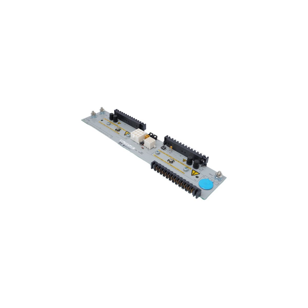
Emerson DeltaV KJ4010X1-BG1 Localbus Right Extender
Emerson DeltaV M-series Localbus Right Extender card (KJ4010X1-BG1 / 12P0830X072) for distributed control systems. Brand new original stock, fully verified with priority shipping options.
Buy original HONEYWELL FS-PDC-CPSET Safety Manager Power Distribution Cable Assemblies. Comprises 2.5 mm² cross-section copper conductors with robust Mate-N-Lock connectors. Genuine USA factory surplus stock ready for dispatch.
The HONEYWELL FS-PDC-CPSET is a high-integrity, heavy-duty industrial power distribution cable assembly engineered exclusively for the Honeywell Safety Manager (Safety Instrumented System – SIS) platform. This specialized dual-cable set is designed to route primary and redundant 24VDC electrical power directly from the main cabinet power bus bars (MB0001) to the main Control Processor Chassis (CPCHAS). It serves as a vital component for ensuring the continuous, fail-safe operation of dual Control Processor architectures.
| Parameter | Specification |
|---|---|
| Model Number | FS-PDC-CPSET |
| Manufacturer | Honeywell |
| Origin | USA |
| Assembly Profile | Dual-cable set for redundant power distribution lines |
| Cable 1 Length (FS-PDC-CP24-1) | 54 cm |
| Cable 2 Length (FS-PDC-CP24-2) | 77 cm |
| Conductor Gauge / Type | CC600 2 x 2.5 mm² heavy-duty copper conductors |
| System Voltage | 24VDC Nominal |
| Bus Bar Connector Type | 2-pole Squeeze-To-Release (D-TAB-200-STR) |
| Controller Side Connector | High-retention Mate-N-Lock connector block |
| Compliance & Approvals | UL Listed, CSA Certified, FM Pending |
| Packaging Dimensions | 24 x 18.8 x 6.5 cm (Shipping container baseline) |
| Weight | 0.38 kg (Net cables) / 0.40 kg (Packaged) |
| Lifecycle Status | Legacy Status (Discontinued by OEM on Dec 31, 2018) |
| HS Code | 8537101190 |
The FS-PDC-CPSET cable set is optimized for clean cable routing and reliable power splitting within standard 800mm or 1000mm deep industrial control cabinets.
The asymmetric lengths (54 cm and 77 cm) align with the strict vertical and horizontal separation guidelines required to prevent overlapping wires in a redundant cabinet layout. The underlying CC600 2 x 2.5 mm² conductor layout provides a highly flexible profile with low internal electrical resistance, preventing voltage drop across the run even under heavy backplane load steps.
Q: Why are there two different lengths included in a single unified cable set?
A: In redundant Honeywell Safety Manager cabinets, Control Processors A and B are physically stacked or separated into different zones of the chassis backplane. The 54 cm cable routes to the nearest power entry terminal block, while the longer 77 cm cable reaches the secondary, redundant power inputs without stretching or straining the wiring.
Q: Can this cable assembly be safely disconnected while the Safety Manager system is under load?
A: No. The bus-bar connection utilizes an insulated “Squeeze-To-Release” (D-TAB-200-STR) mechanical tab design to ease system maintenance. However, uncoupling a primary power line while a safety system is live can cause localized electrical arcing or trigger an unexpected power loss alarm on that controller tier.
Q: What are the risks of substituting standard commercial 2.5 mm² wire for this factory set?
A: The FS-PDC-CPSET features factory-molded, heavy-duty Mate-N-Lock and D-TAB terminations that match the high-vibration requirements of industrial environments. Utilizing non-OEM substitution wires risks loose connections, invalidates UL/CSA safety certifications, and may introduce voltage ripple across the safety processors.
MB0001 mains bus bar area is clean and free of dust before mounting. Depress the mechanical levers on the D-TAB-200-STR housing, slide the tab home onto the bus bar connection, and release the lever to lock it firmly into place.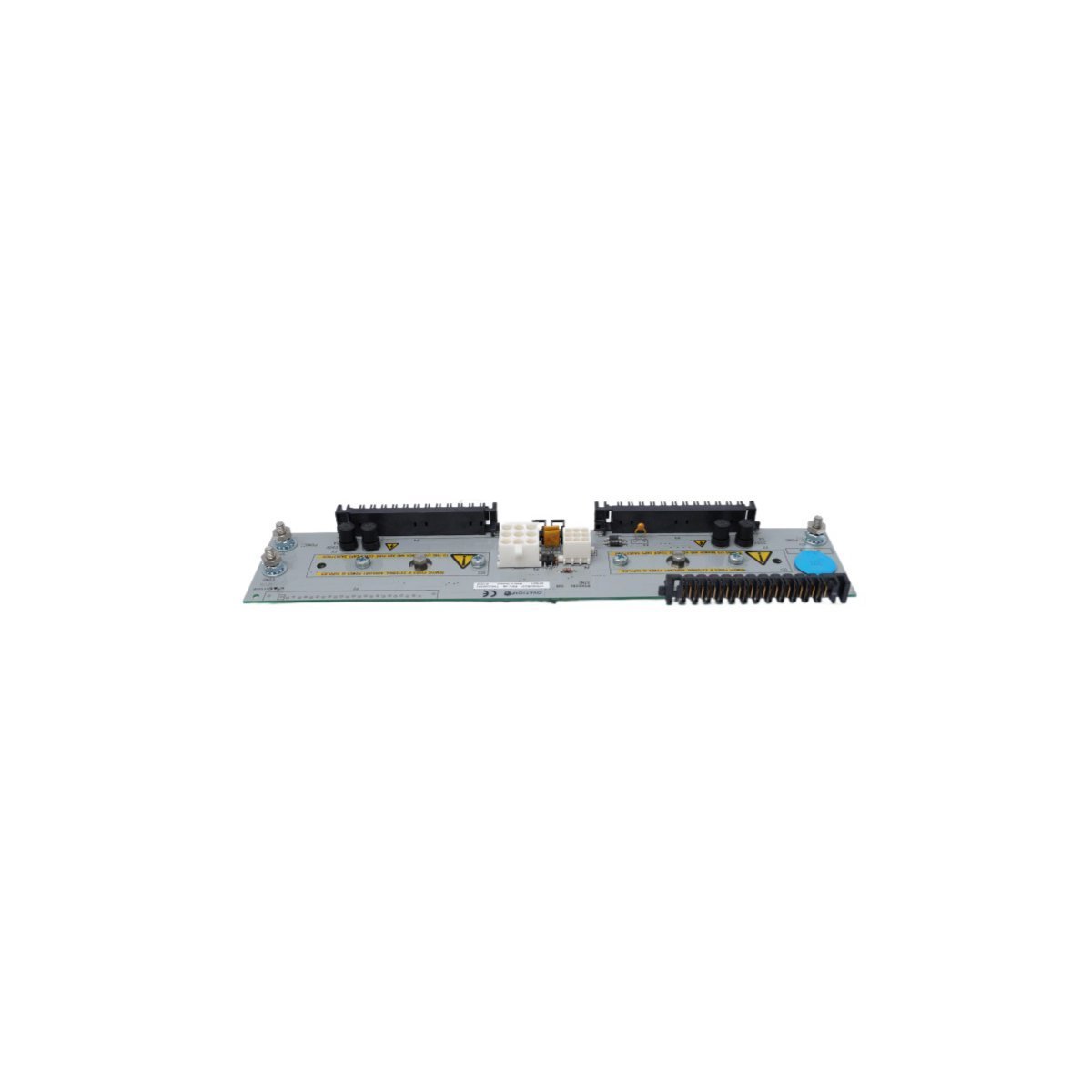
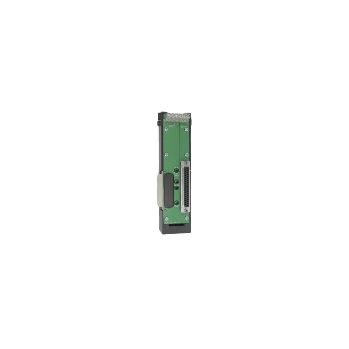
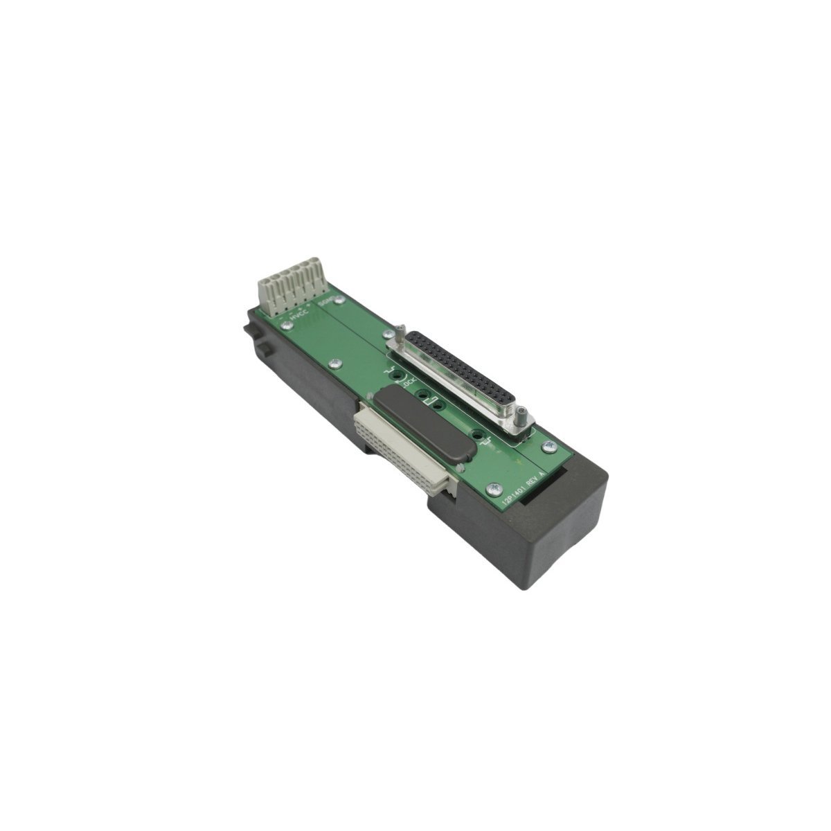
The Emerson Ovation 1P00028G01 Remote Node Transition Panel provides robust signal routing and high-integrity electrical isolation for legacy Ovation Distributed Control Systems (DCS). Operating at 220V AC across an ultra-wide temperature range of -40°C to +85°C, this compact transition panel eliminates field line noise and ensures reliable, deterministic peer-to-peer communication between remote I/O nodes and central controllers in demanding industrial environments.
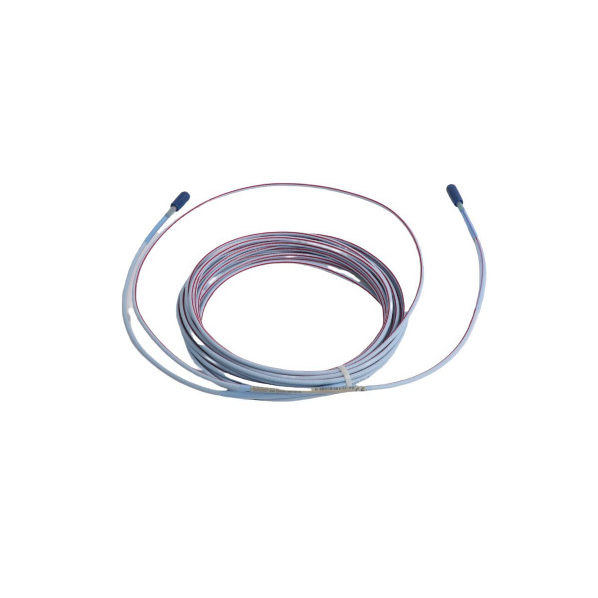

The Bently Nevada 330192-00-28-05-00 is an 8 mm Extended Temperature Range (ETR) proximity probe component of the 3300 XL Proximity Transducer System. Its primary function is to perform non-contact measurement of relative displacement on rotating and reciprocating machinery. The probe operates on an eddy current principle. When paired with a 3300 XL extension cable and Proximitor Sensor, it forms a tuned oscillator circuit that emits a high-frequency radio frequency (RF) field from the probe tip. This field induces eddy currents on the surface of the observed conductive target, typically a machine shaft. The interaction between the RF field and the eddy currents results in a change in the oscillator's amplitude, which is directly proportional to the gap between the probe tip and the target. The Proximitor Sensor demodulates this RF signal into a precise DC voltage. This voltage signal is then transmitted to a monitoring system, such as the Bently Nevada 3500 Series, where it is processed to provide critical measurements including radial vibration, axial position (thrust), and rotational speed (when used in a Keyphasor configuration). The 330192-00-28-05-00 is constructed with a Polyphenylene Sulfide (PPS) tip and a stainless steel body, ensuring robust performance in high-temperature industrial environments.
| Parameter | Specification |
|---|---|
| Manufacturer | Bently Nevada |
| Part Number | 330192-00-28-05-00 |
| Product Type | 3300 XL 8 mm ETR Proximity Probes |
| Condition | Brand New |
| Warranty | 12 Months |
| Linear Range | 2.0 mm (80 mils) |
| Scale Factor | 7.87 V/mm (200 mV/mil) ±5% |
| Probe Tip Temperature Range | -34 °C to +260 °C (-30 °F to +500 °F) |
| Total Length | 0.5 meters (1.6 feet) |
| Case Length | 2.8 inches (71.1 mm) |
| Connector Type | Miniature coaxial ClickLoc connector, gold-plated |
| Probe Tip Material | Polyphenylene Sulfide (PPS) |
The 330192-00-28-05-00 probe is engineered for high-reliability machine protection and condition monitoring in demanding industrial sectors. In Oil & Gas applications, its ETR specification (up to +260 °C) allows for installation on high-temperature machinery such as gas turbines, steam turbines, and centrifugal compressors, where probes are often located near hot casings or in high-temperature bearing housings. In Power Generation, it provides essential rotor dynamics data for turbine-generator sets, ensuring safe operation within design limits. The 3300 XL system, including the 330192-00-28-05-00 probe, is designed for high immunity to radio frequency interference (RFI/EMI), a common issue in industrial plants. Its robust construction with an AISI 304 stainless steel case provides excellent resistance to corrosion from hydrocarbons and other process chemicals. The system's stability and repeatability are critical for API 670 compliant machinery protection systems, providing accurate data for automatic shutdown logic and predictive maintenance analysis.
Q: What systems is the 330192-00-28-05-00 compatible with?
A: The 330192-00-28-05-00 probe must be used as part of a complete, electrically matched 3300 XL 8 mm transducer system. This system includes a 3300 XL Proximitor Sensor (e.g., P/N 330180-XXXX-XX) and a


The Bently Nevada 330104-00-14-10-11-00 Proximity Probes is a genuine industrial component.
| Condition | New |
We are committed to protecting your privacy. The information collected here is strictly used to provide the requested quotes, technical support, and relevant industrial automation solutions.