The GE IC694MDL645, also cataloged as the IC694MDL645 Digital Input Module, operates as a dedicated hardware component for signal acquisition within PACSystems RX3i control networks. Incoming field signals are processed through sixteen discrete channels, and the resulting state data is transmitted to the backplane. Electrical compatibility with both positive and negative logic configurations is maintained, and operational states are continuously monitored via integrated LED indicators.
Hardware Specifications
Parameter
Specification
Model
IC694MDL645
Brand
GE
Origin
USA
Weight
0.3 kg
Dimensions
3.5 cm x 13.2 cm x 13.5 cm
Operating Temp
Standard Industrial Range
Power Consumption
Backplane Dependent
Input Channels
16
Rated Voltage
24 VDC
ON-state Voltage
11.5 VDC to 30 VDC
OFF-state Voltage
0 VDC to 5 VDC
Response Time
7 ms (typical)
PLC and Control Network Integration
System communication velocity and deterministic performance are regulated by the PACSystems backplane architecture. Signal integrity is preserved through high-level galvanic isolation, rated at 1500 VAC for one minute, whereby electrical noise interference is mitigated. Furthermore, firmware flash compatibility is ensured during module replacement, provided that the backplane remains energized within the specified voltage tolerances. The module is engineered for integration within both local and remote RX3i I/O racks, while support for RX7i systems is provided exclusively in distributed I/O configurations.
Frequently Asked Questions
Q: Is the module capable of being hot-swapped while the system is powered?
A: Yes, the module is designed to be extracted and inserted while the RX3i backplane is energized; however, field wiring must be verified to ensure no short-circuit conditions are created during the removal process.
Q: How is the signal response time managed in high-speed applications?
A: A typical response time of 7 milliseconds is imposed by the hardware filter circuits. This latency is inherent and should be accounted for when high-speed pulse capture is required.
Field Installation Guidelines
The module is to be mounted onto the designated RX3i backplane slot. A mechanical click is heard when the module is fully seated.
Prior to wiring, the 24 VDC power supply must be verified for voltage stability.
Signal wires are to be connected to the terminal block. A secure, firm connection is required to prevent intermittent signal loss caused by vibration.
Shielding must be grounded at the designated earth terminal to ensure that electromagnetic interference is properly diverted.
Once the module is seated and wired, the status LEDs are to be inspected for illumination corresponding to active field device states.
The GE Multilin UR7BH is a high-performance communication processor module for Universal Relay systems. It supports IEC 61850 and DNP 3.0 protocols. This module provides dual-redundant Ethernet connectivity for reliable industrial automation and power system protection.
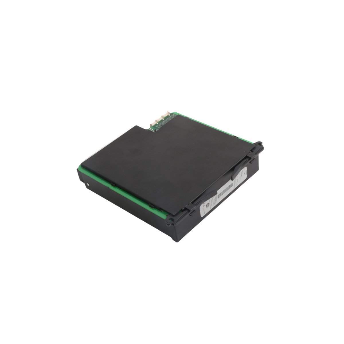
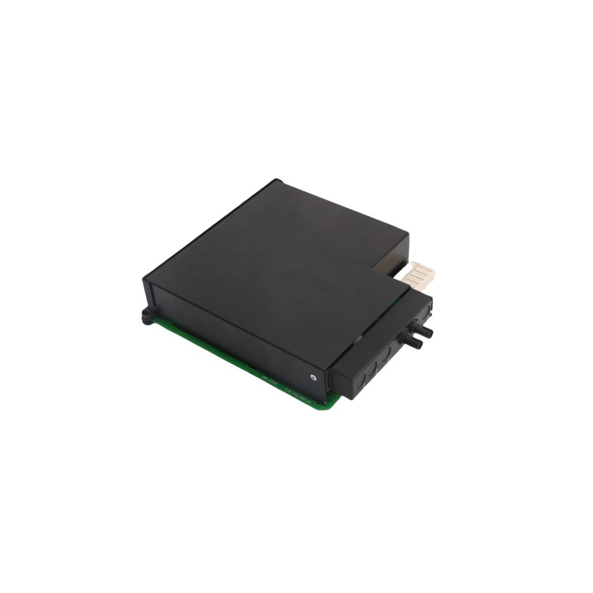
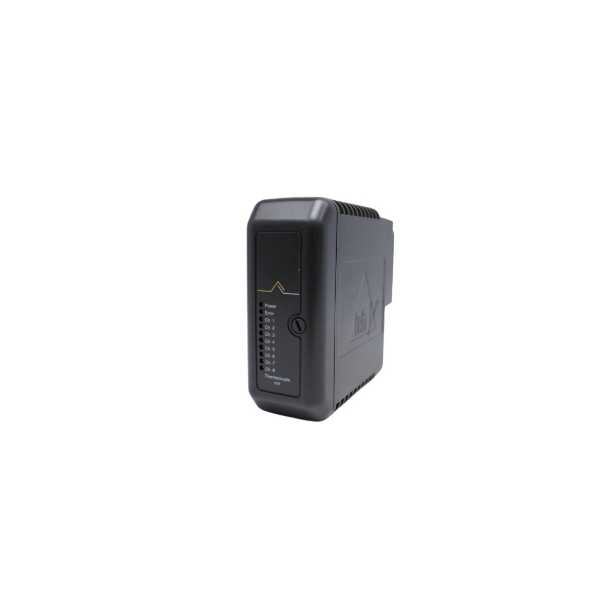
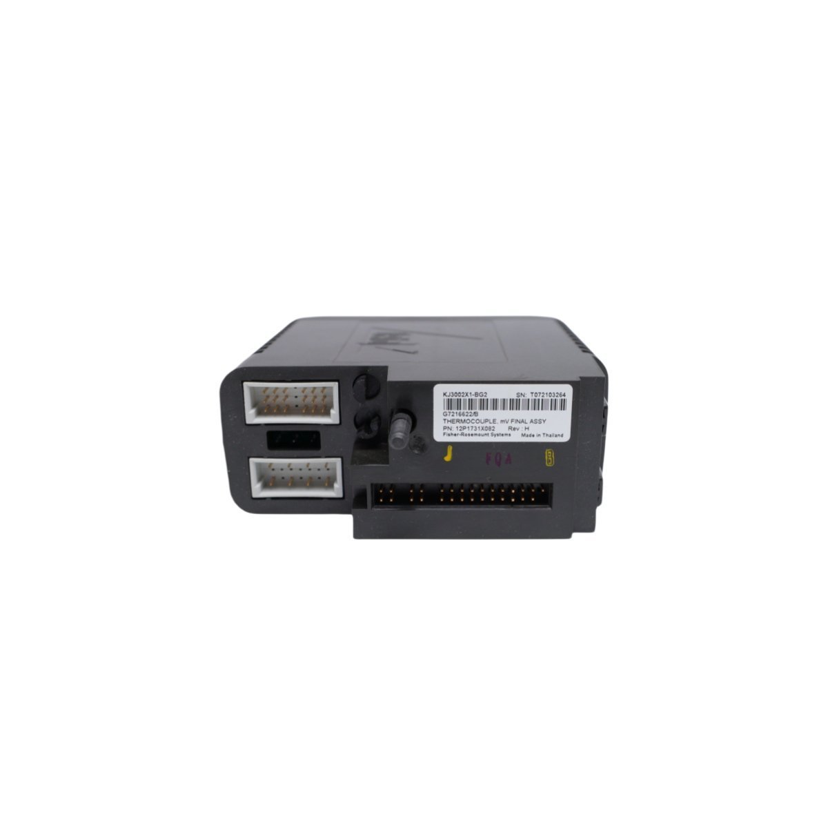
The Emerson KJ3002X1-BG2 (12P1731X082) is a DeltaV M-series Digital Input Module. It provides redundant, isolated signal processing for critical industrial DCS applications.
The GE Multilin UR6FH is a high-speed digital I/O module for the Universal Relay series. It features 8 fast Form-C outputs and operates on 24 VDC. This module provides rapid response times and secure signal interfacing for advanced power system protection and substation automation applications.
The Yokogawa ADV142-P10 S1 is a 32-channel digital input module for CENTUM VP systems. It features 24V DC isolated inputs and supports hot-swapping for continuous DCS operation. This high-density module provides reliable status monitoring for industrial automation and process control.
The Yokogawa ADV151-P53 S2 is a high-density 32-channel digital input module for CENTUM VP systems.It provides 24V DC isolated signal acquisition with advanced noise filtering. This durable, hot-swappable module ensures reliable status monitoring for critical industrial automation processes.
The Yokogawa ADV142-S02 S1 is a high-performance 32-channel digital input module for CENTUM VP systems. It features 24V DC isolated inputs and robust noise protection. This reliable I/O module supports hot-swapping and provides clear LED diagnostics for industrial automation status monitoring.
The Yokogawa ADV159-P00 is a 32-channel digital input module designed for the CENTUM VP system. It offers isolated signal acquisition, supports dual-redundancy, and features a hot-swappable design. This module ensures high-speed, reliable monitoring for critical industrial automation tasks.
The Yokogawa ADV141-P12 S1 is a 16-channel isolated digital input module for CENTUM VP systems. It features high-voltage opto-isolation, low power consumption, and hot-swap support. This Japan-made module ensures precise signal acquisition for demanding industrial control applications.
The ICS Triplex T3419 is a high-performance Digital Input module for the Regent Control System. It offers high-density channel monitoring, TMR fault tolerance, and ultra-fast 5ms response times, making it the ideal choice for critical safety and emergency shutdown applications in harsh industrial environments.
The Yokogawa ADV151-E50 S2 is a 32-channel digital input module designed for the CENTUM VP DCS.It provides high-speed discrete signal processing and supports Sequence of Events (SOE) data capture. This Japan-manufactured module offers reliable sink/source compatibility for demanding industrial control applications.
The Yokogawa ADV161-P50 S2 is a 64-channel high-density digital input module for the CENTUM VP DCS. Engineered for 24 VDC signals, this FIO module provides reliable, isolated data acquisition and a compact footprint for demanding industrial automation environments.
The HIMA F3236 is a 16-channel digital input module engineered for SIL 3 safety applications. Compatible with HIMA HIMax and HIQuad systems, it offers robust signal monitoring and integrated diagnostics to ensure the highest levels of safety and uptime in critical industrial processes.
We are committed to protecting your privacy. The information collected here is strictly used to provide the requested quotes, technical support, and relevant industrial automation solutions.