


Sale!
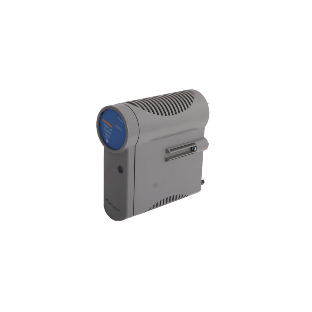
Honeywell CV-DSC25K PlantCruise SCADA Points Adder
Honeywell CV-DSC25K PlantCruise SCADA Points Adder. Brand New, Original Stock. Global Shipping. Adds 25,000 points to Experion PKS DCS systems. Order now.
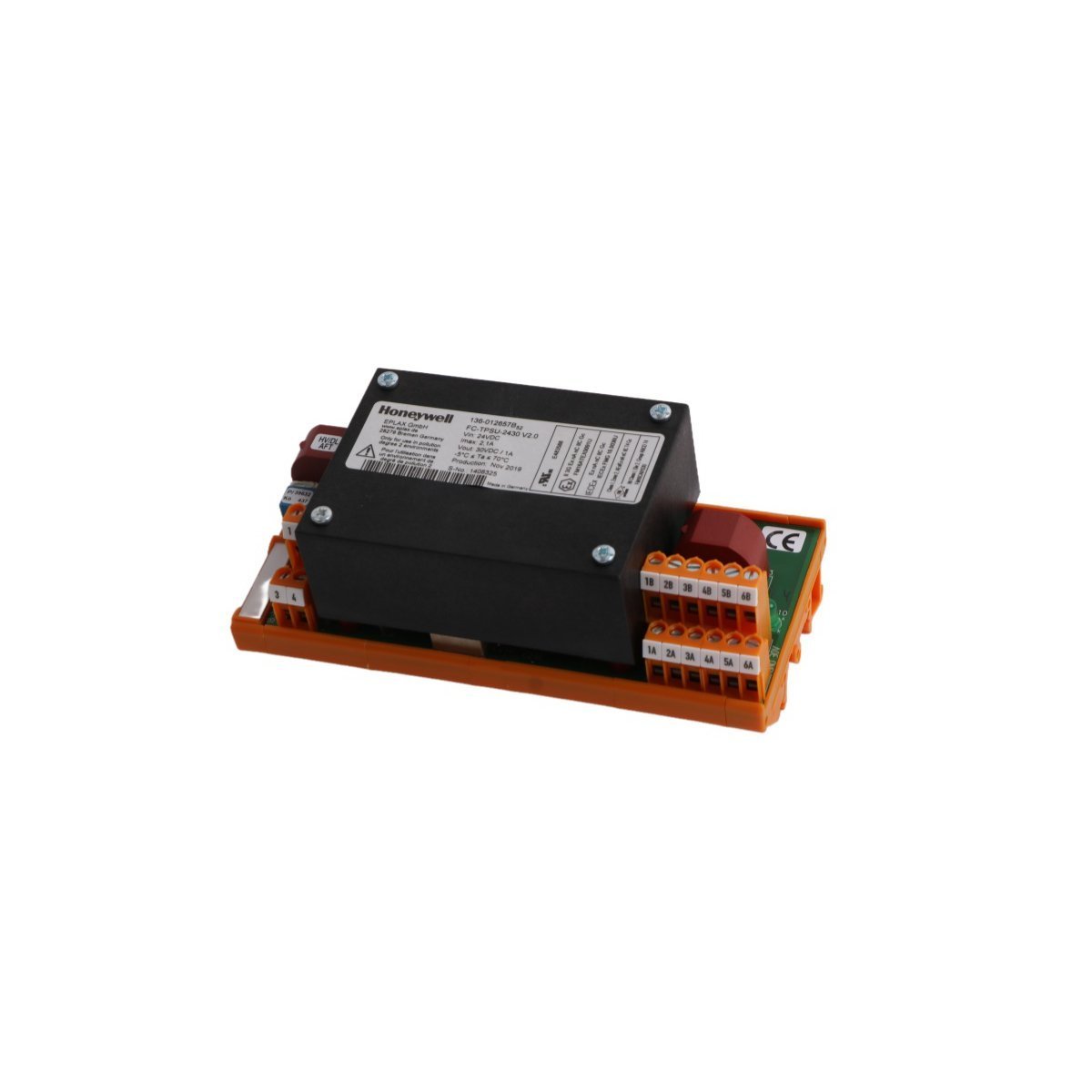
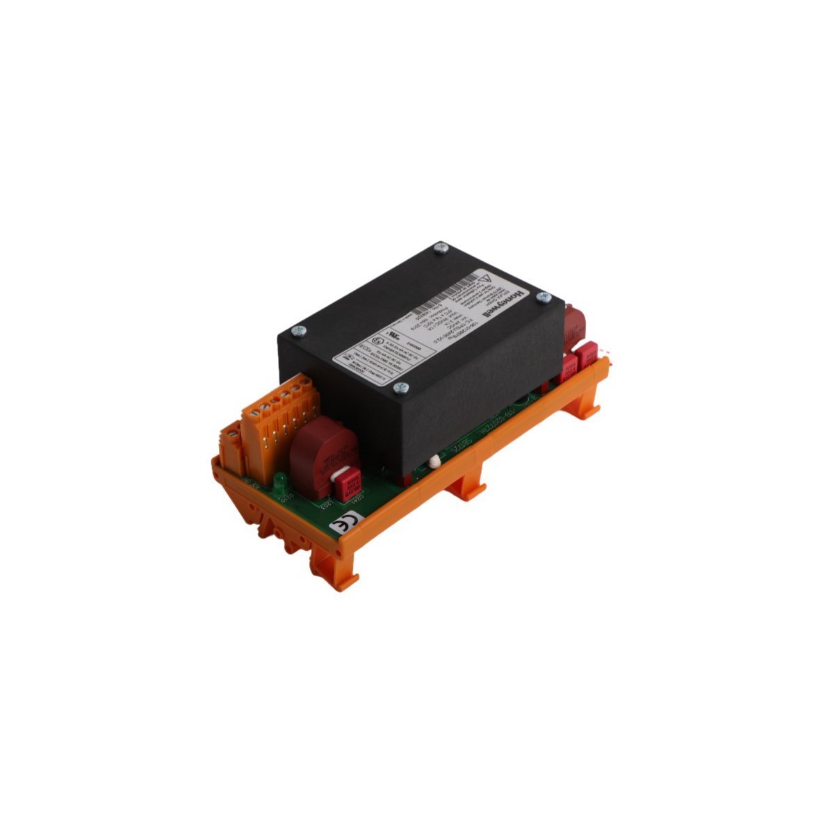
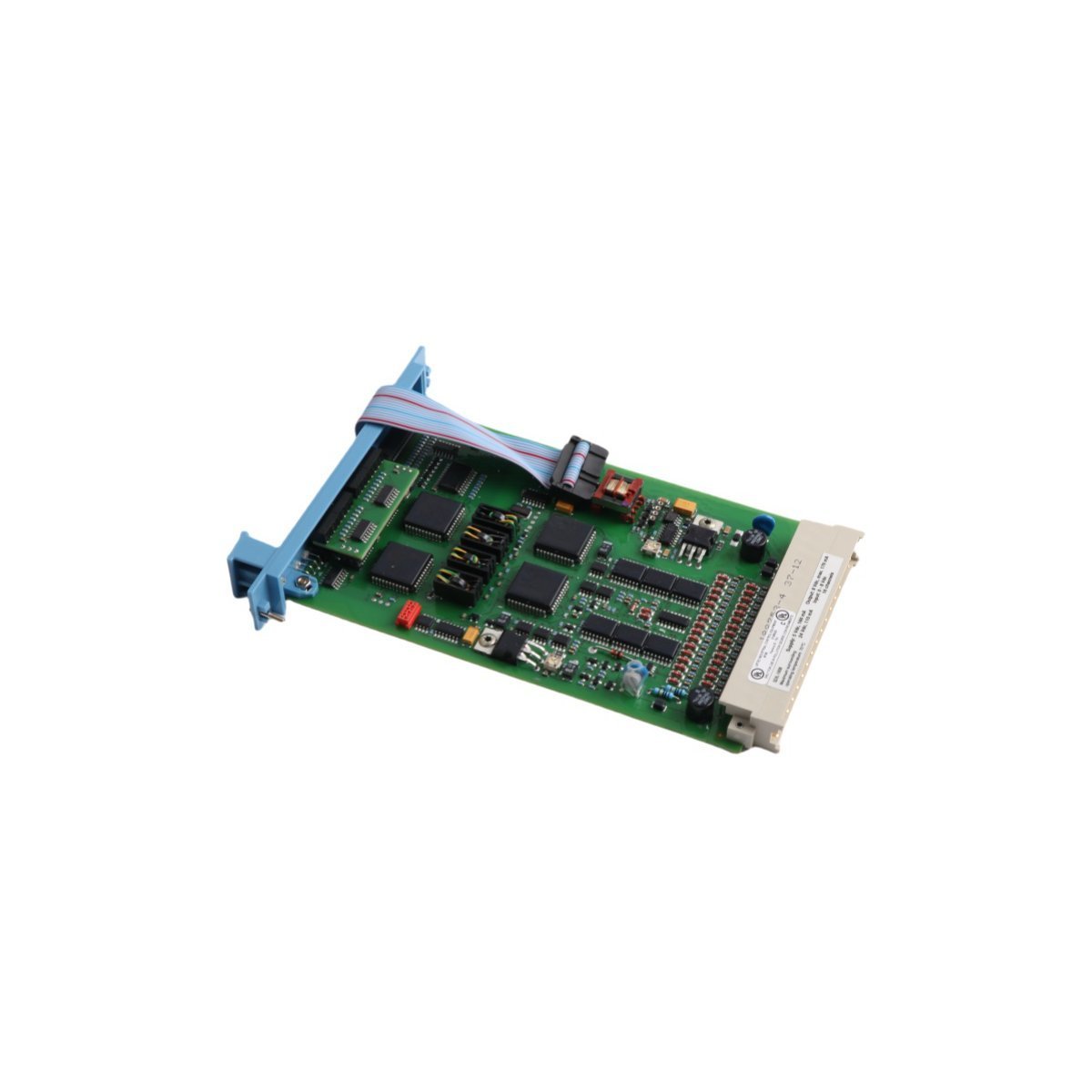
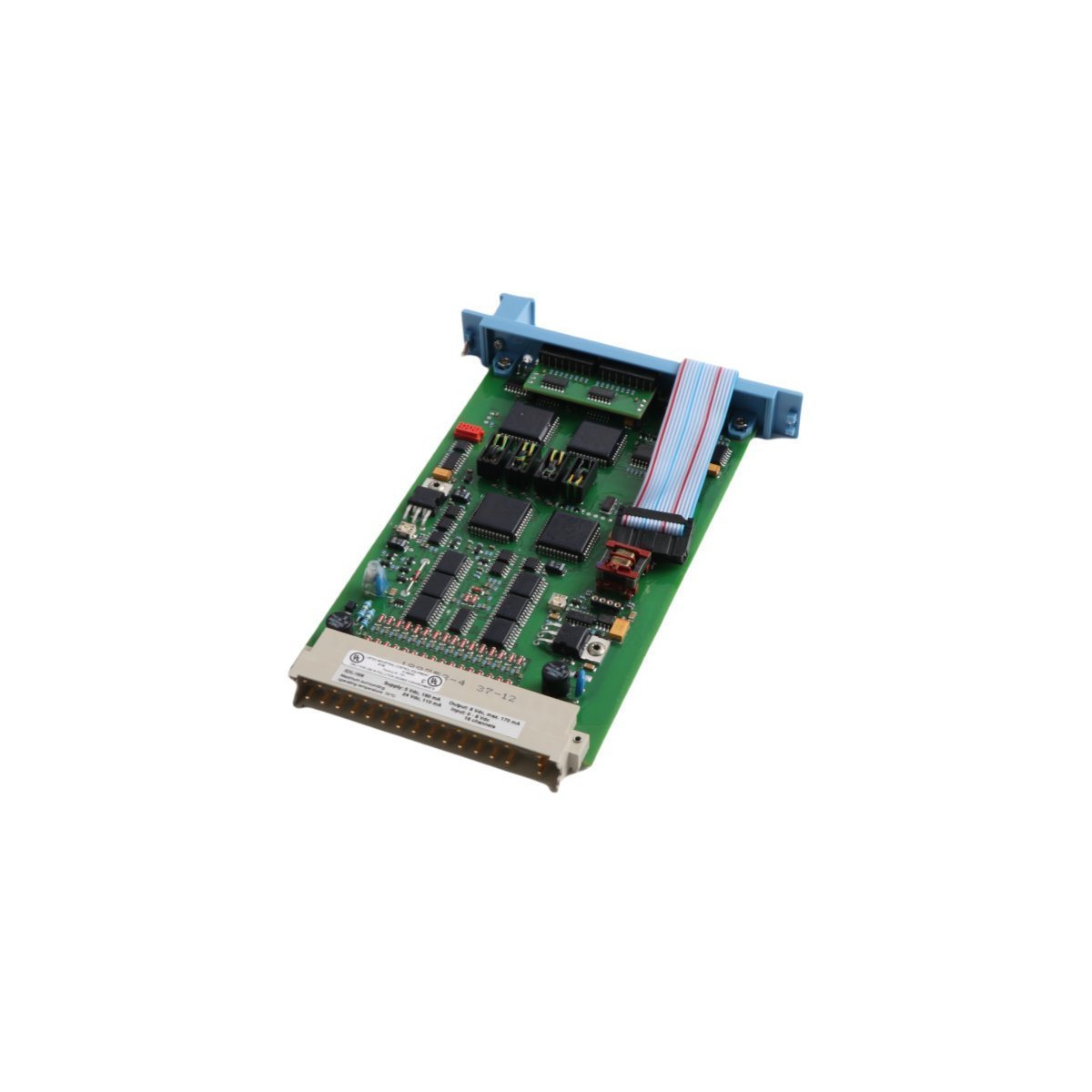
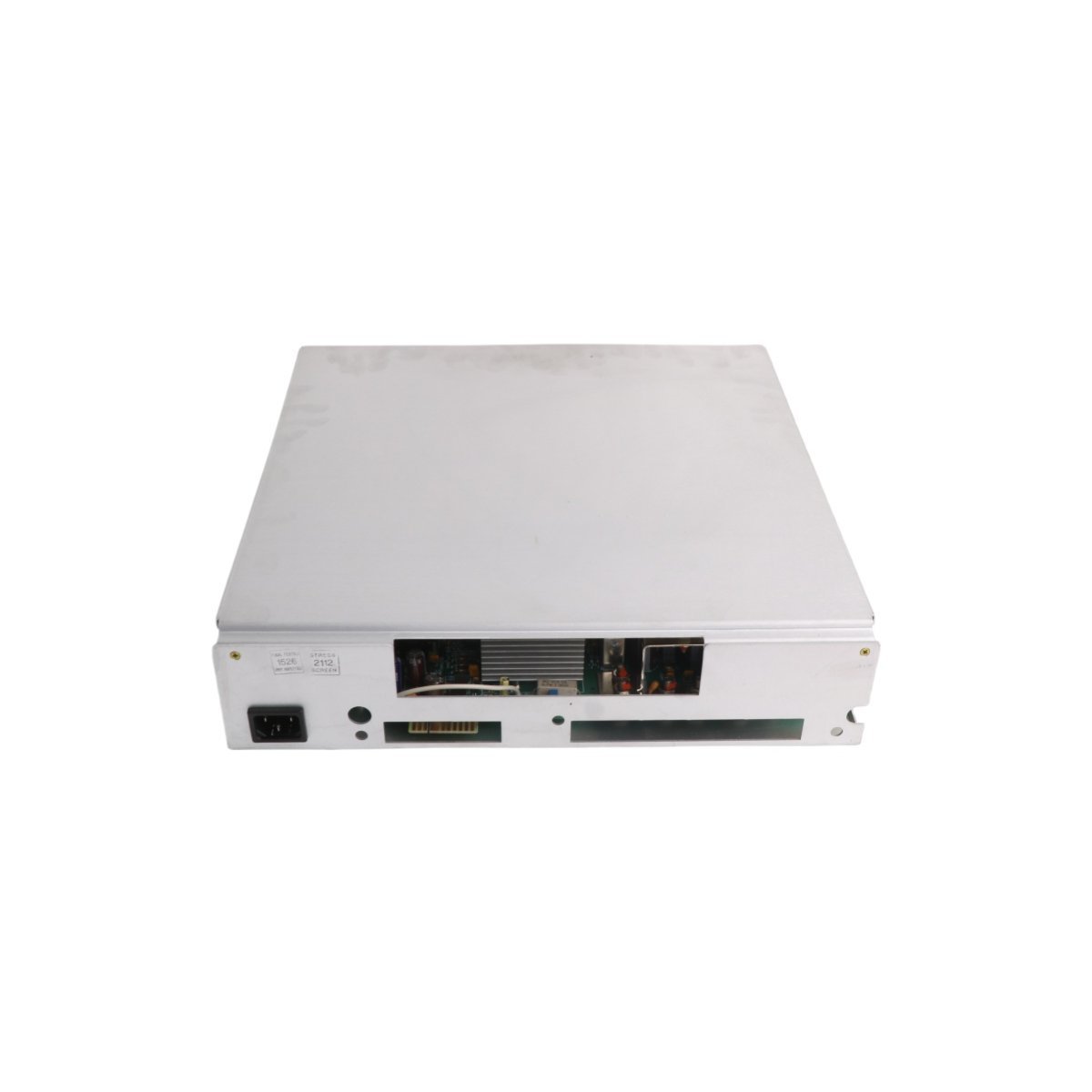
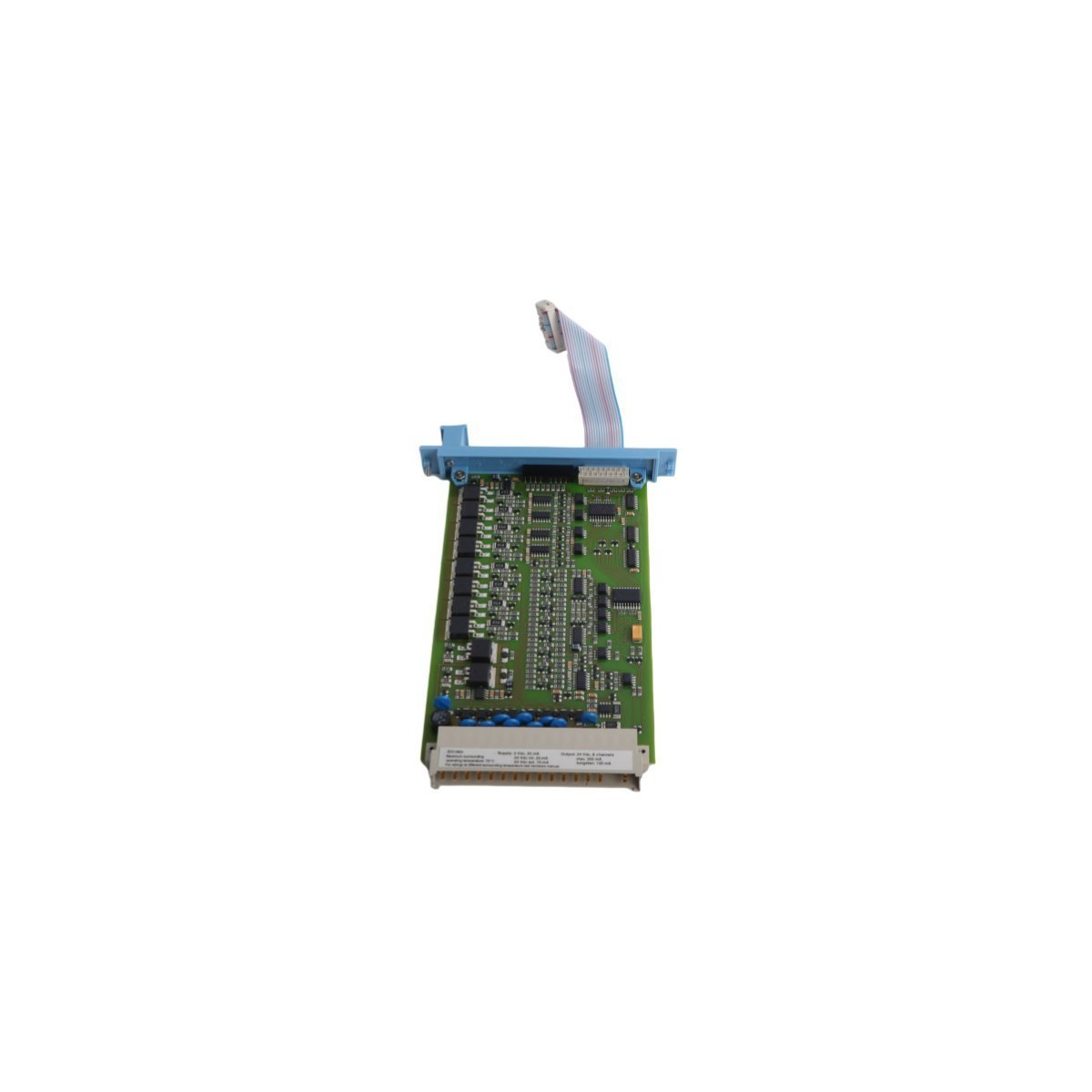
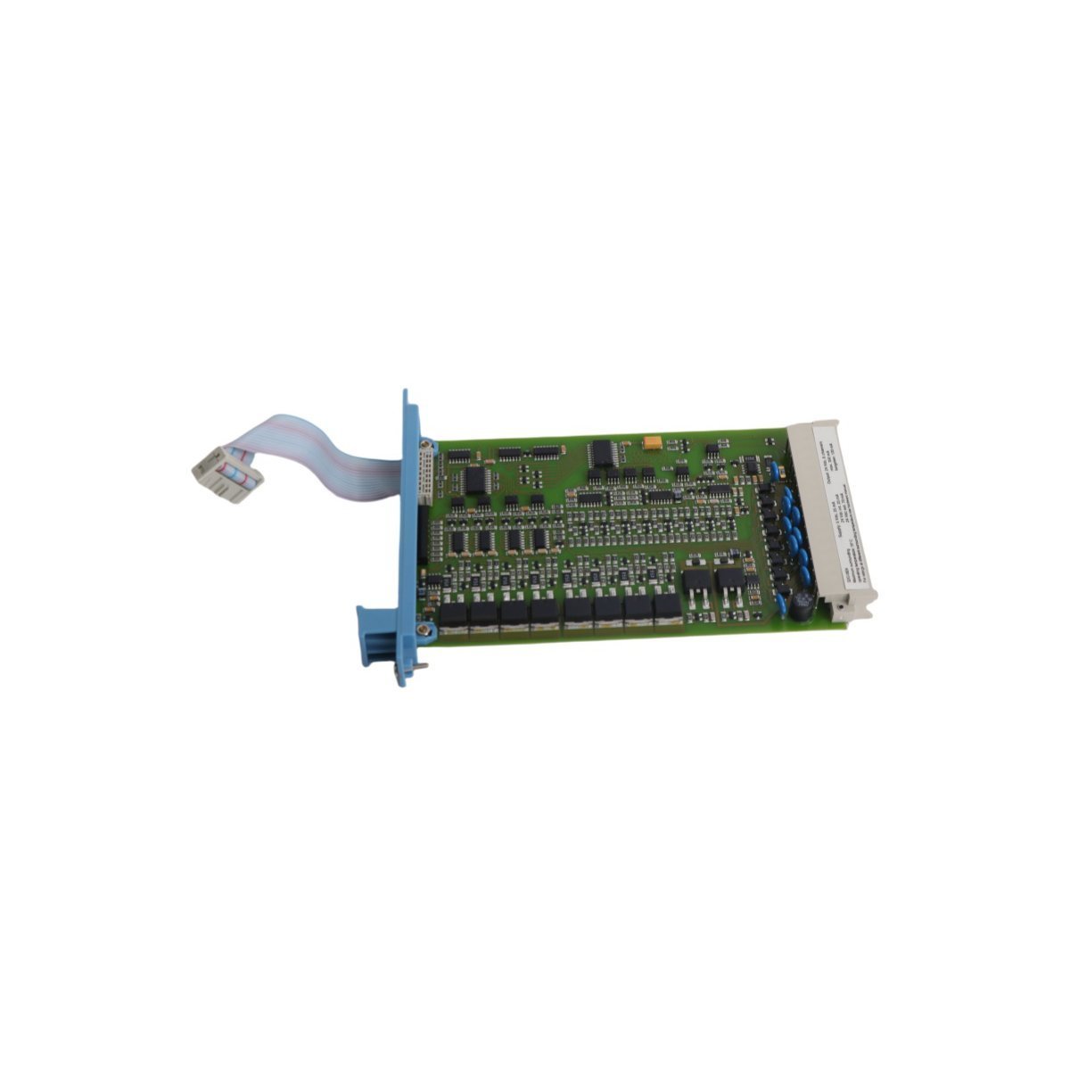
Configured for signal interfacing in Experion PKS architectures, the Honeywell 51305072-700 (51305072-700 Input Output Board) provides direct physical/electrical execution for process data acquisition and signal routing.
| Parameter | Specification |
|---|---|
| Model | 51305072-700 |
| Brand | Honeywell |
| Origin | USA |
| Weight | 0.18 kg |
| Dimensions | 2 x 13.5 x 23.8 cm |
| Operating Temp | Standard Industrial |
| Power Consumption | Not Specified |
| System | DCS |
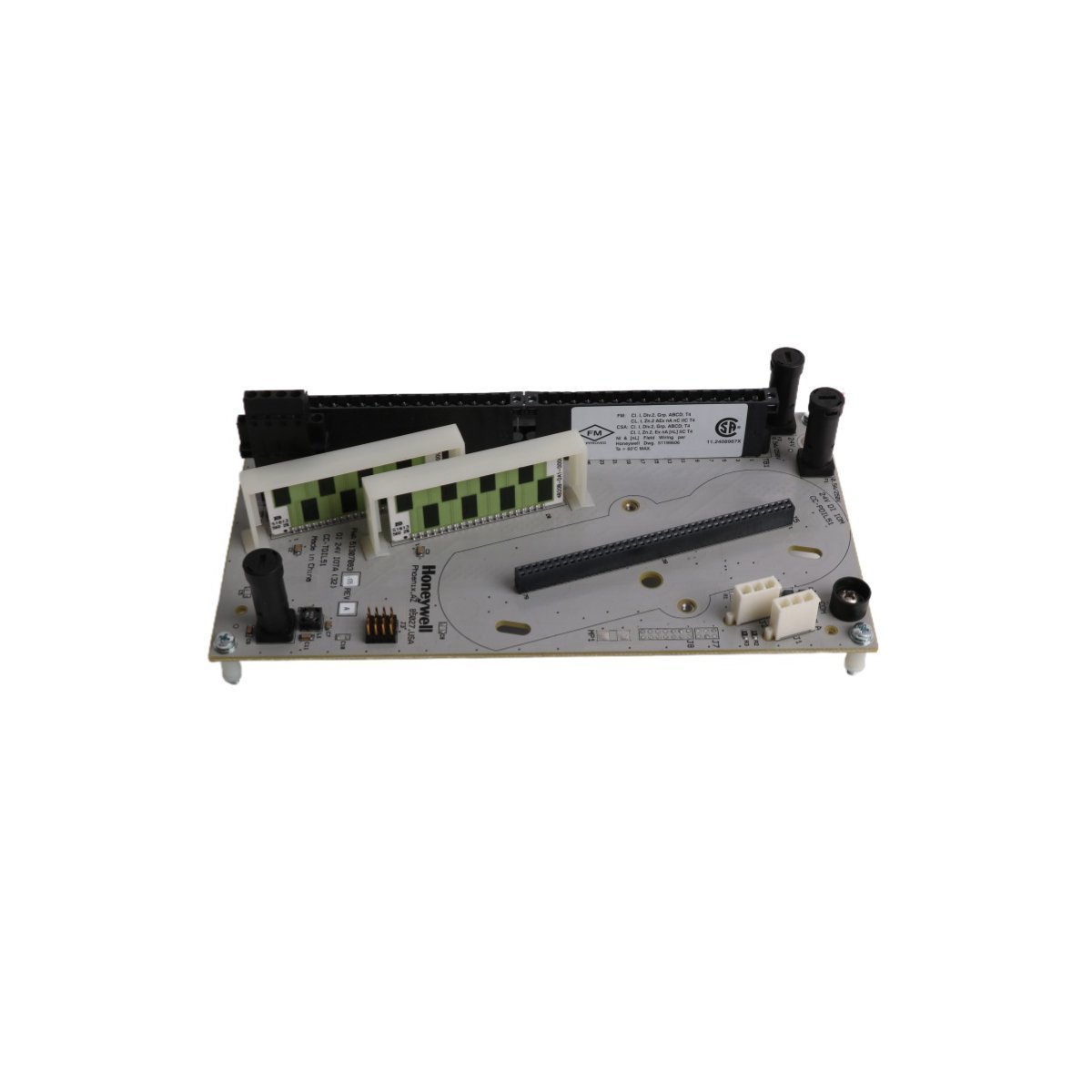
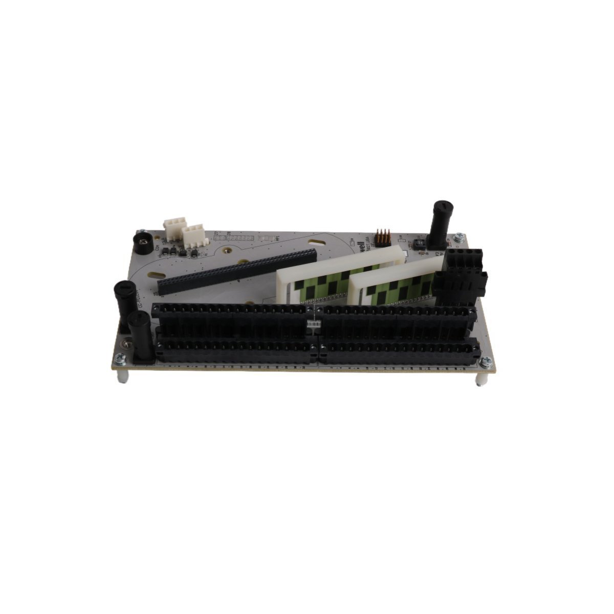
Initially, signal integrity is maintained within the DCS environment through the implementation of dedicated input termination pathways. Subsequently, data acquisition is facilitated by the 51305072-700, whereby field sensor signals are processed and, furthermore, routed to the control cabinet backplane. In this configuration, channel-to-channel isolation is utilized; consequently, common-mode noise propagation is prevented, thereby ensuring that 4-20 mA HART loop protocol signals or discrete inputs are accurately translated. Moreover, cold junction compensation (CJC) is managed via the associated termination logic, while loop impedance is calibrated to match specific field requirements. Following this, data transmission is executed through standardized backplane interfaces. In addition, these interfaces are continuously monitored so as to minimize signal attenuation across long-distance field wiring. Ultimately, by adhering to these protocols, system stability is enhanced; likewise, operational accuracy is preserved throughout the signal path.
Q: Does the 51305072-700 support hot-swapping within an energized cabinet backplane?
A: Hot-swapping is not supported for this module. Power must be isolated from the specific backplane segment prior to module insertion or extraction to prevent damage to the backplane communication bus.
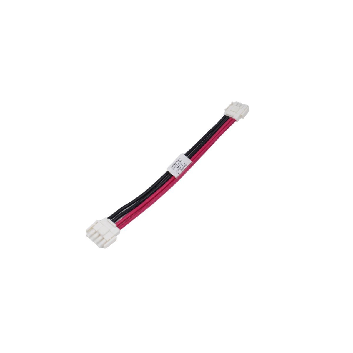
Q: How is the physical grounding of the board managed during installation?
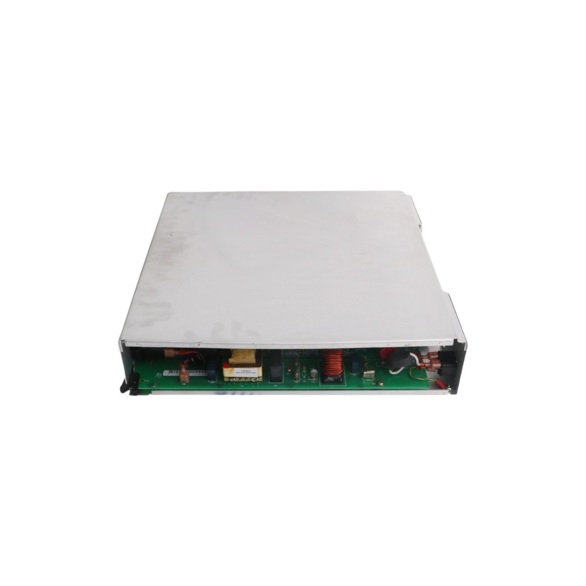
A: Grounding is established via the mechanical engagement of the module chassis with the cabinet backplane bus, which provides a common reference potential for signal shielding.
The 51305072-700 must be installed within a controlled cabinet environment, observing standard industrial hardware mounting practices.


We are committed to protecting your privacy. The information collected here is strictly used to provide the requested quotes, technical support, and relevant industrial automation solutions.