
Sale!
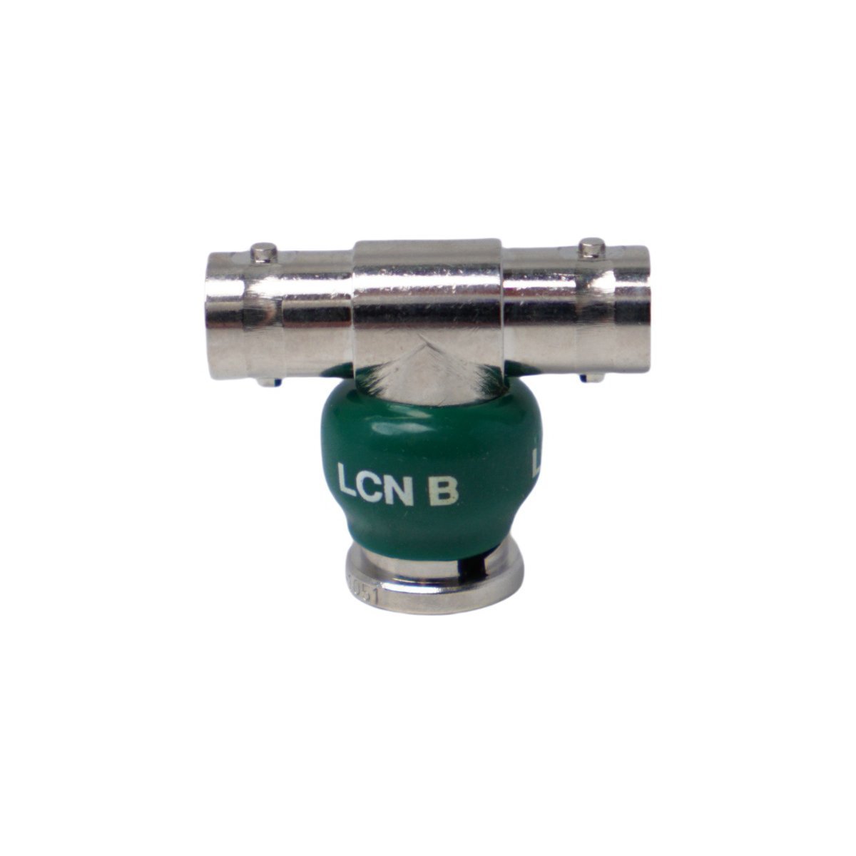
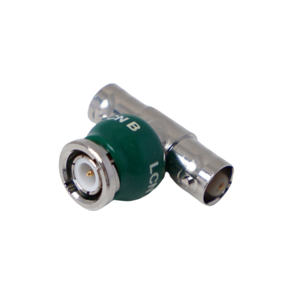
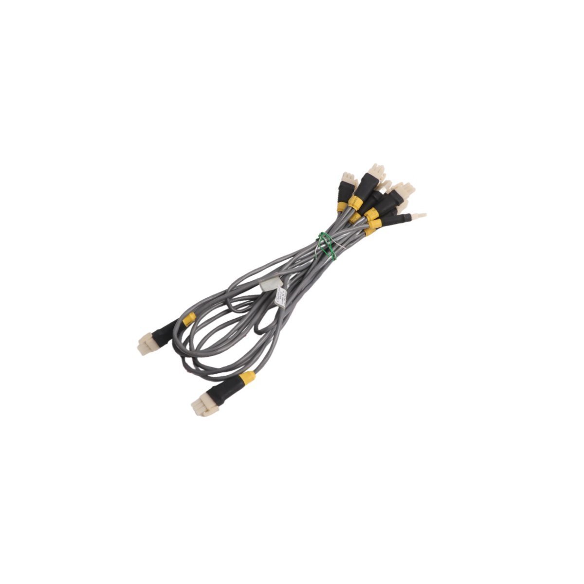
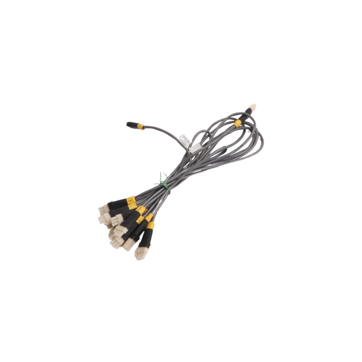
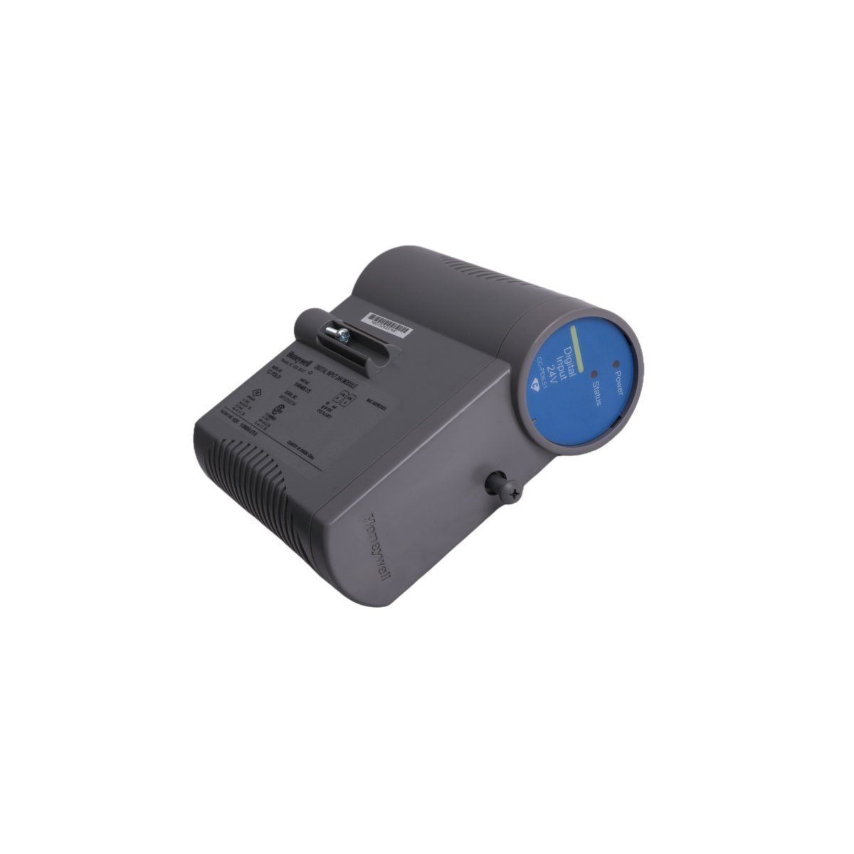
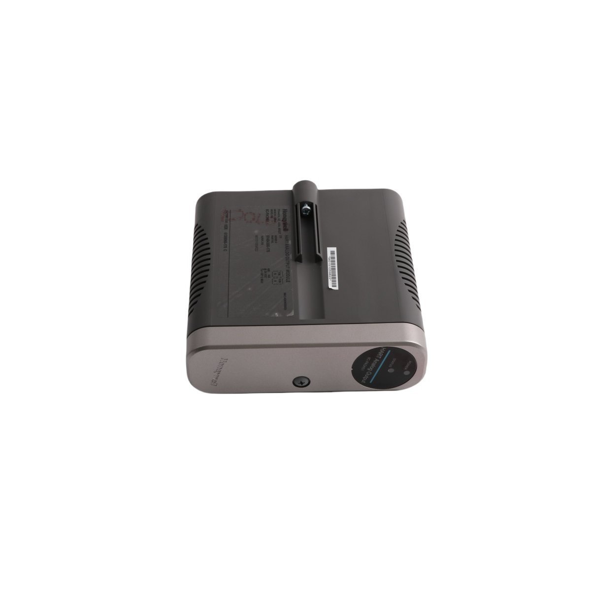
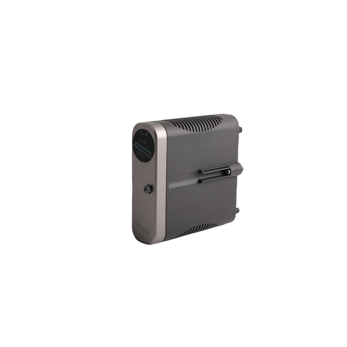
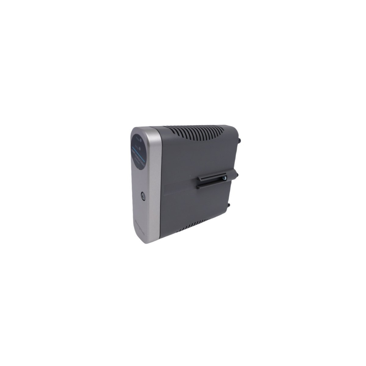
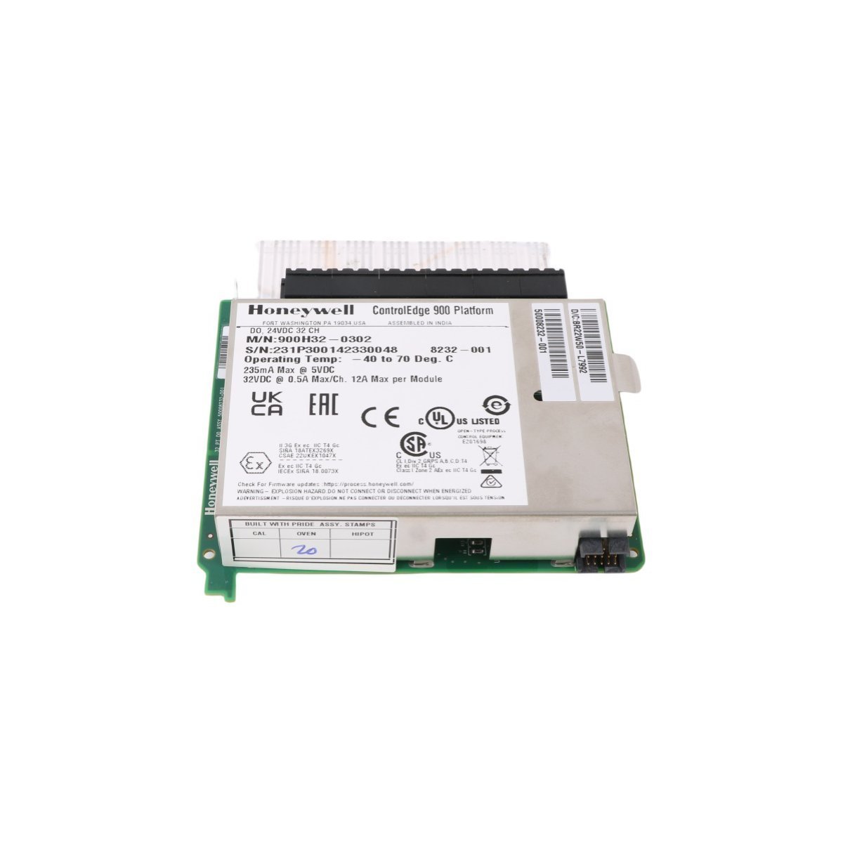
Honeywell 51196041-100 Experion PKS Panel Accessory
Honeywell 51196041-100 Experion PKS Panel Accessory component. Brand New, Original Stock, Global Shipping. High-precision technical specs and field guidelines.
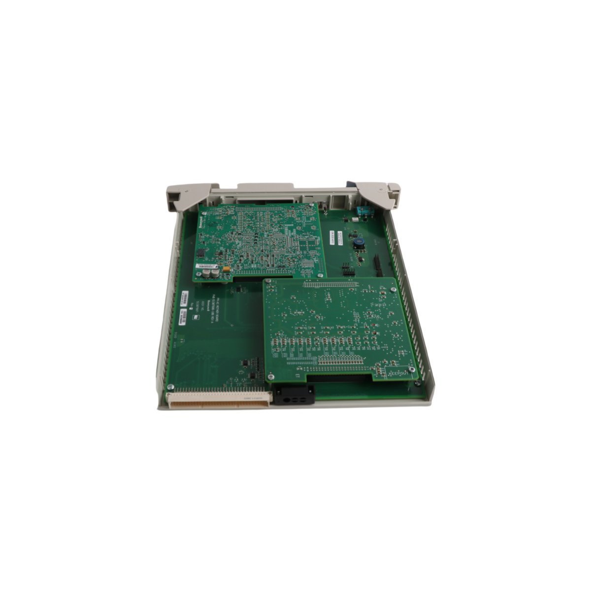
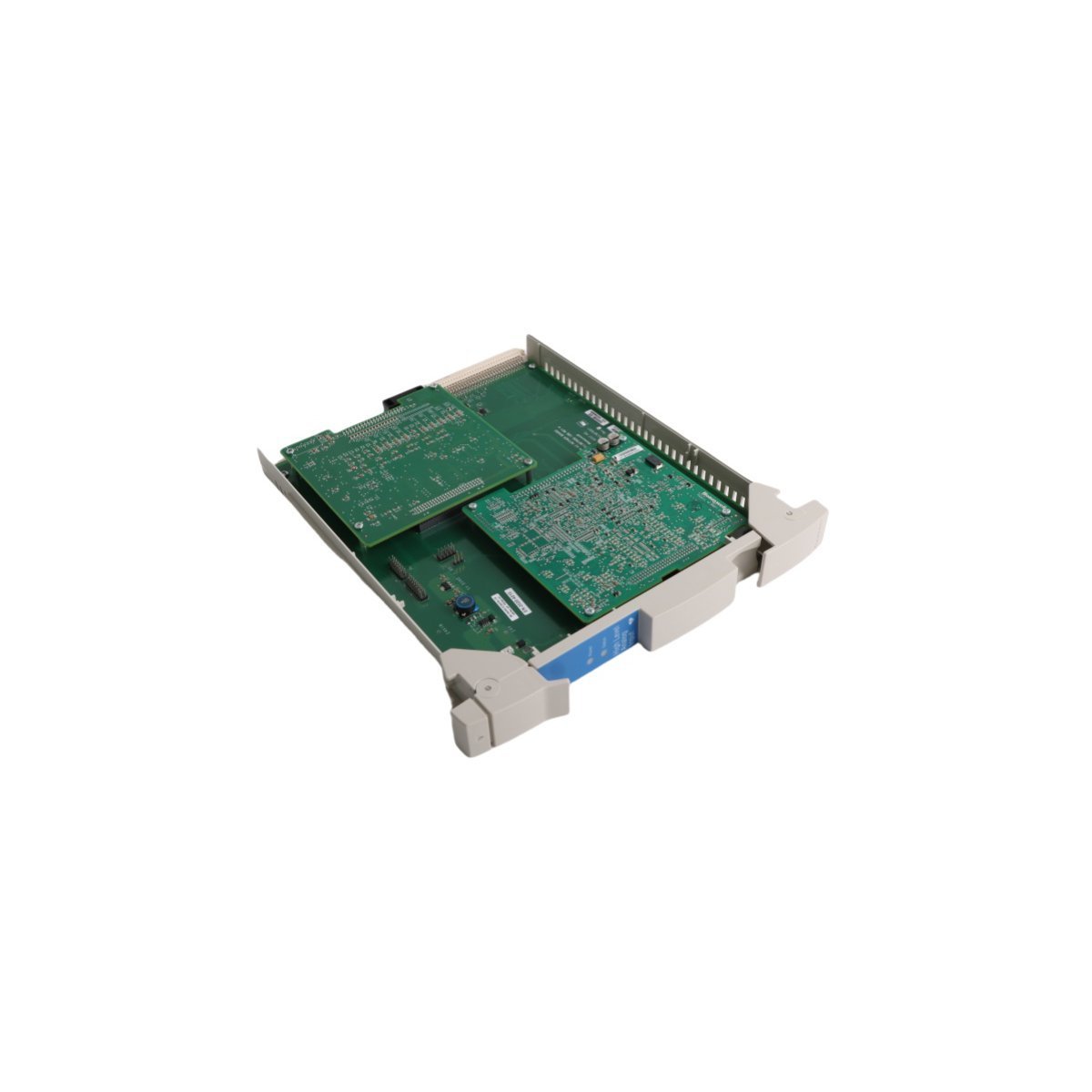
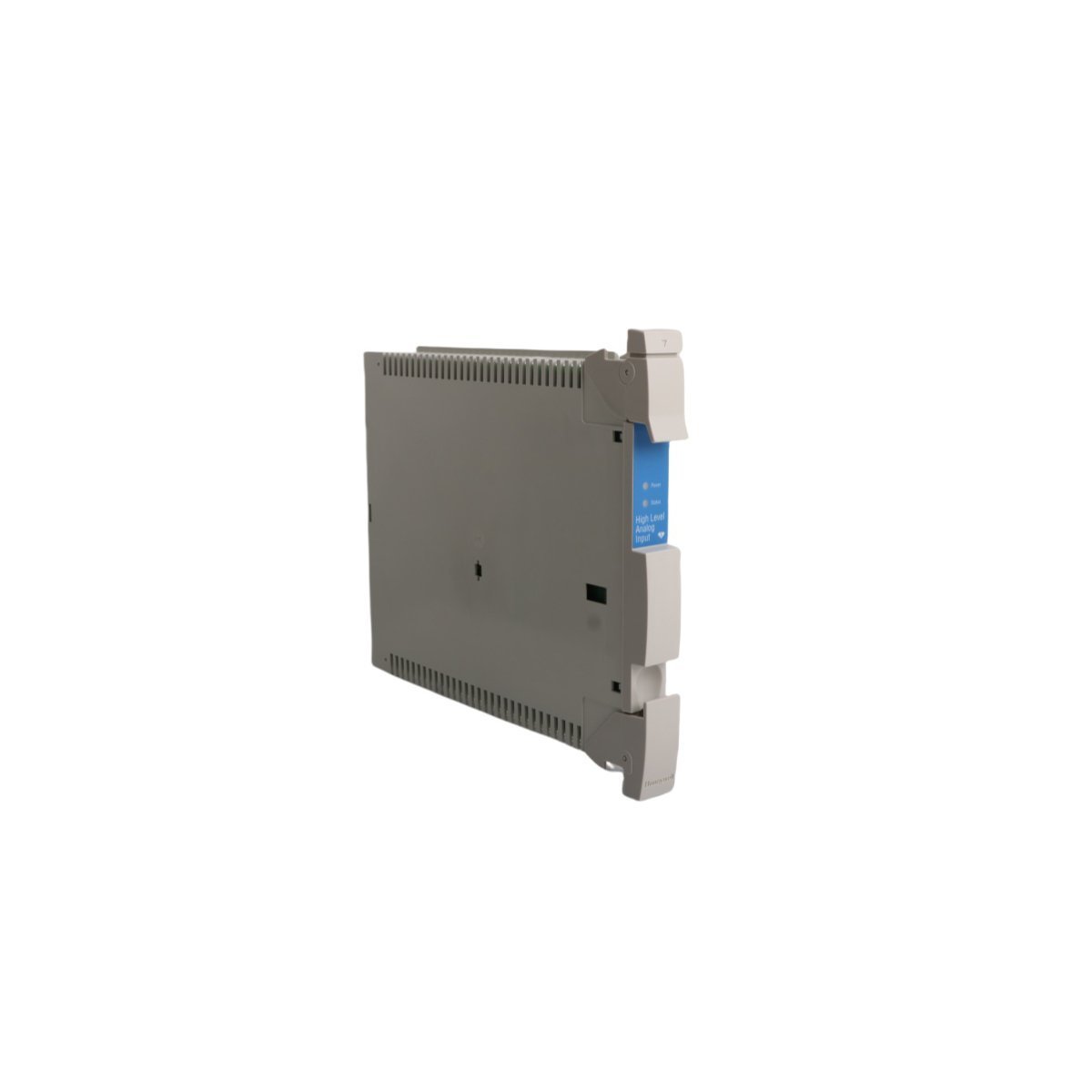
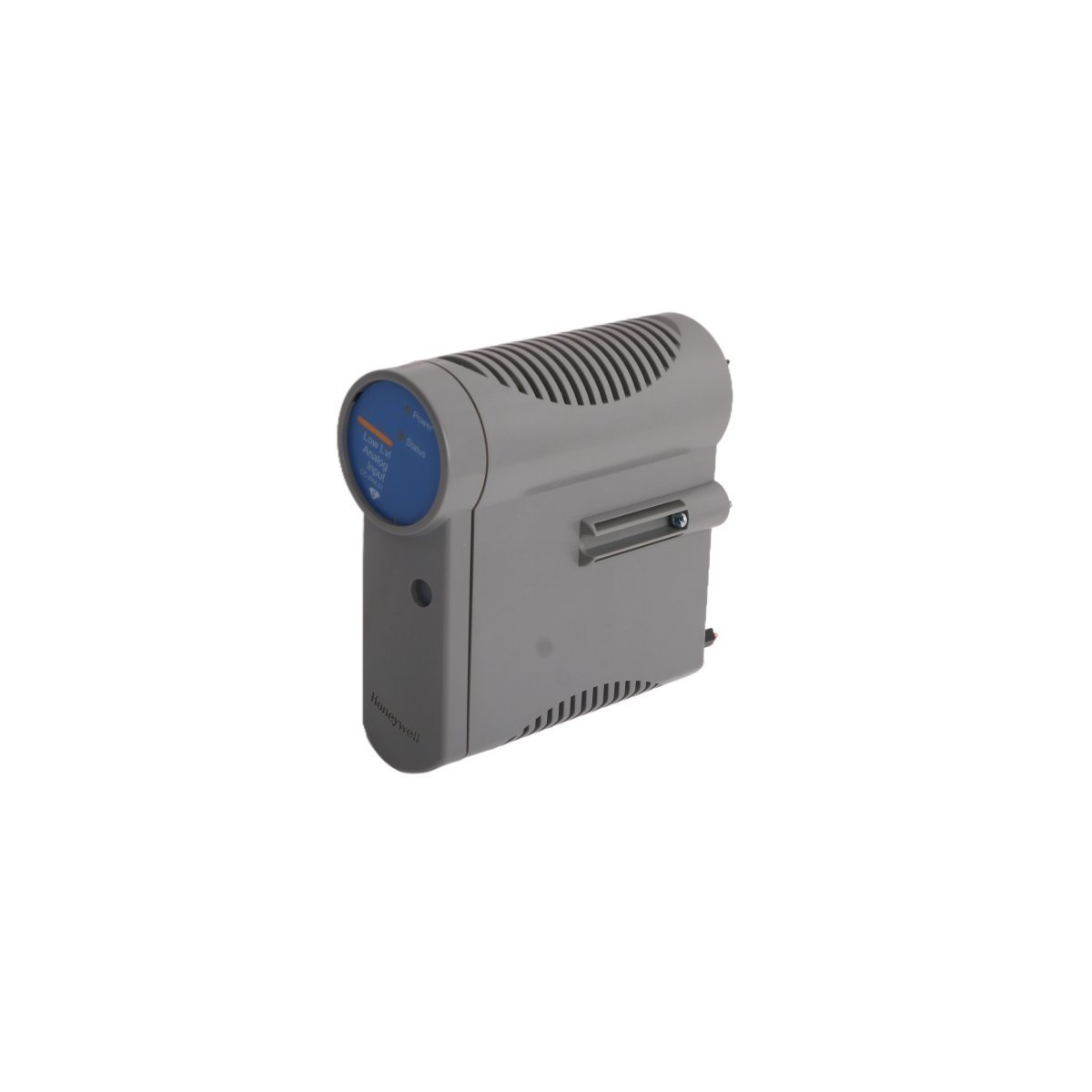
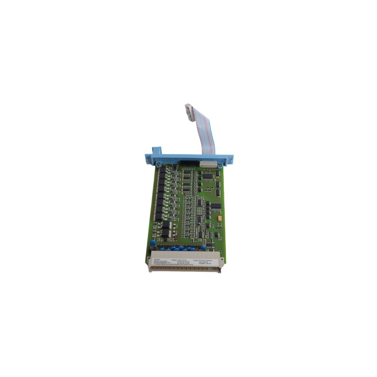
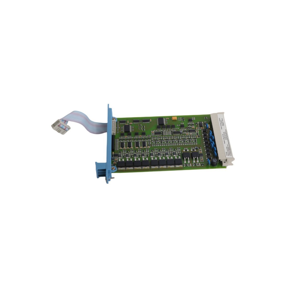
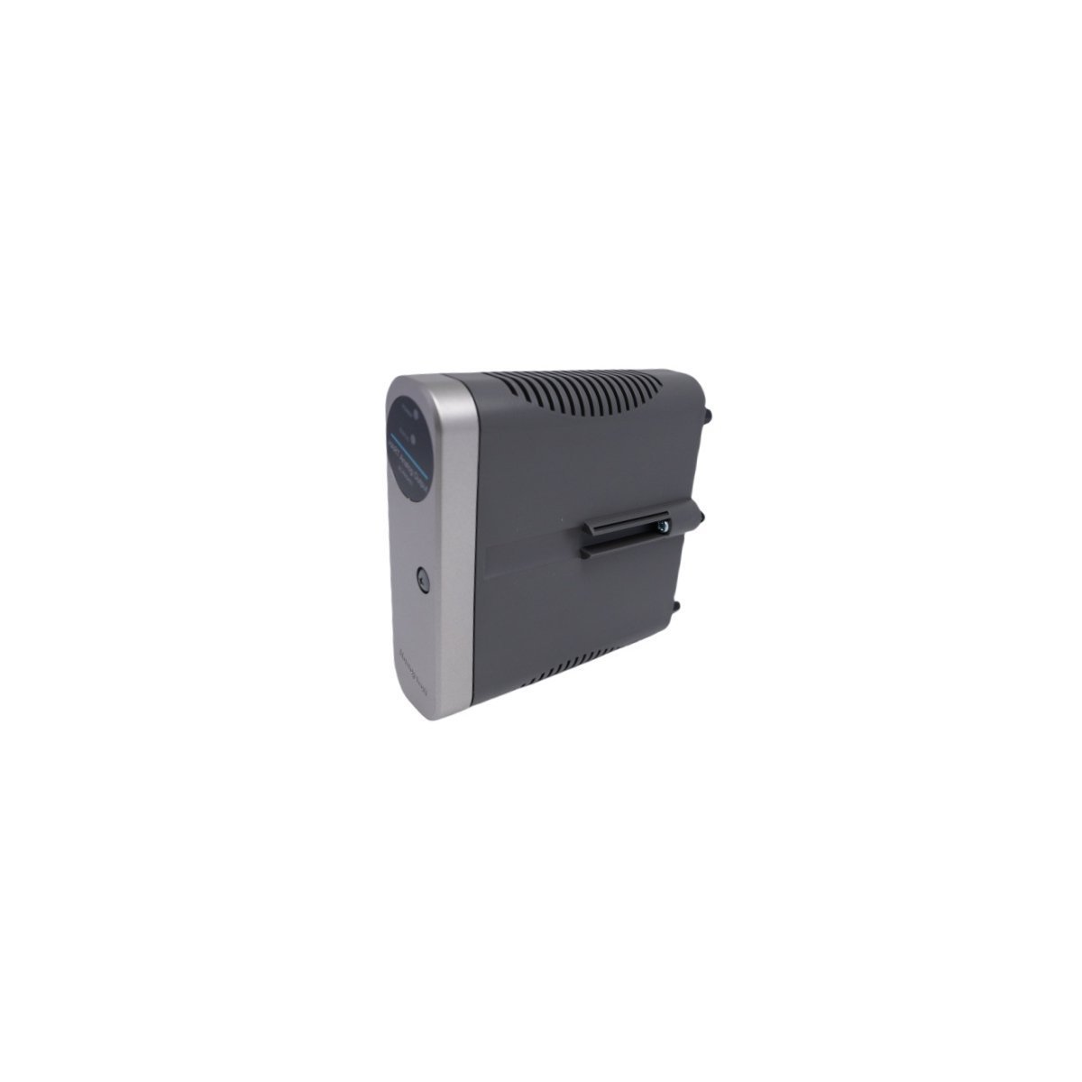
The Honeywell 51307687-176, also cataloged as the 51307687-176 High Level Analog Input Module, operates as a dedicated hardware component for high-level analog signal acquisition and processing within Honeywell Experion PKS DCS platforms.
| Parameter | Specification |
|---|---|
| Model | 51307687-176 |
| Brand | Honeywell |
| Origin | USA |
| Weight | 0.74 kg |
| Dimensions | 2.8 x 31.8 x 27.8 cm |
| Operating Temp | 0 to 60 deg C |
| Power Consumption | Standard Backplane Bus Drain |
| Product Series | Experion PKS |
| Module Type | REV A High Level Analog Input |
| System | DCS |
| Status | Active |
| HS Code | 8537101190 |
The 51307687-176 processes high-level process inputs (such as 4-20 mA loop currents and 1-5 VDC transmitter voltages) directly into digitized process values for real-time DCS loop control. Integrated channel-to-channel isolation and input filtering mitigate common-mode noise, ground loops, and signal degradation across field wiring networks.
Dedicated cold junction compensation (CJC) processing and onboard analog-to-digital conversion ensure tight measurement accuracy without loading controller execution cycles. Internal bus interface circuits communicate field variables across the Experion PKS I/O chassis, enforcing determinism across critical control loops.
Q: What input signal ranges are supported by the 51307687-176 analog input module?
A: The module is designed for standard high-level field instrumentation signals, accommodating 4-20 mA current loops and 1-5 VDC inputs from process transmitters.
Q: Can the 51307687-176 module be hot-swapped during active system operation?
A: Yes, the module supports insertion and removal under power within an operational Experion PKS I/O rack provided proper ESD grounding precautions and chassis safety protocols are observed.









We are committed to protecting your privacy. The information collected here is strictly used to provide the requested quotes, technical support, and relevant industrial automation solutions.