
Sale!
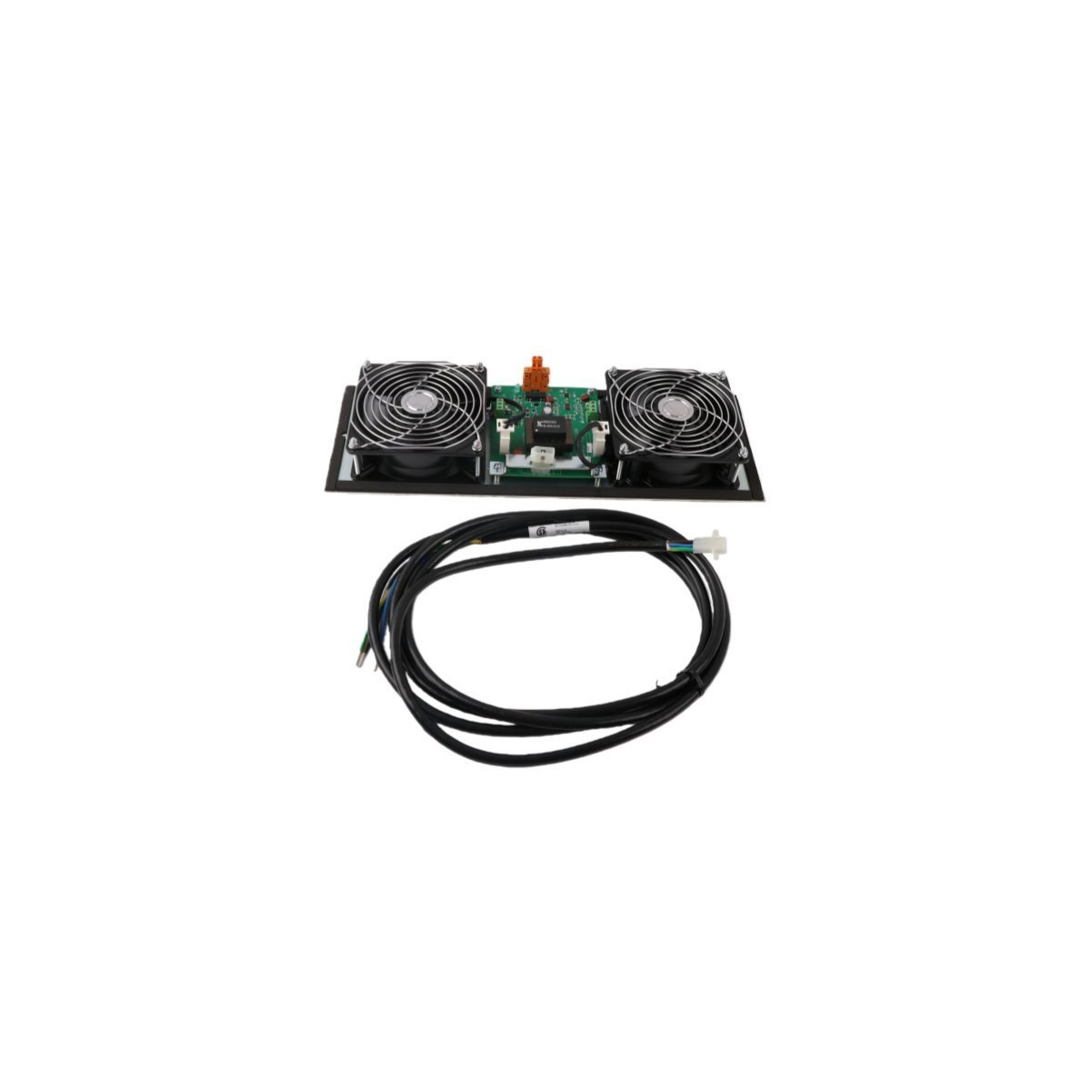
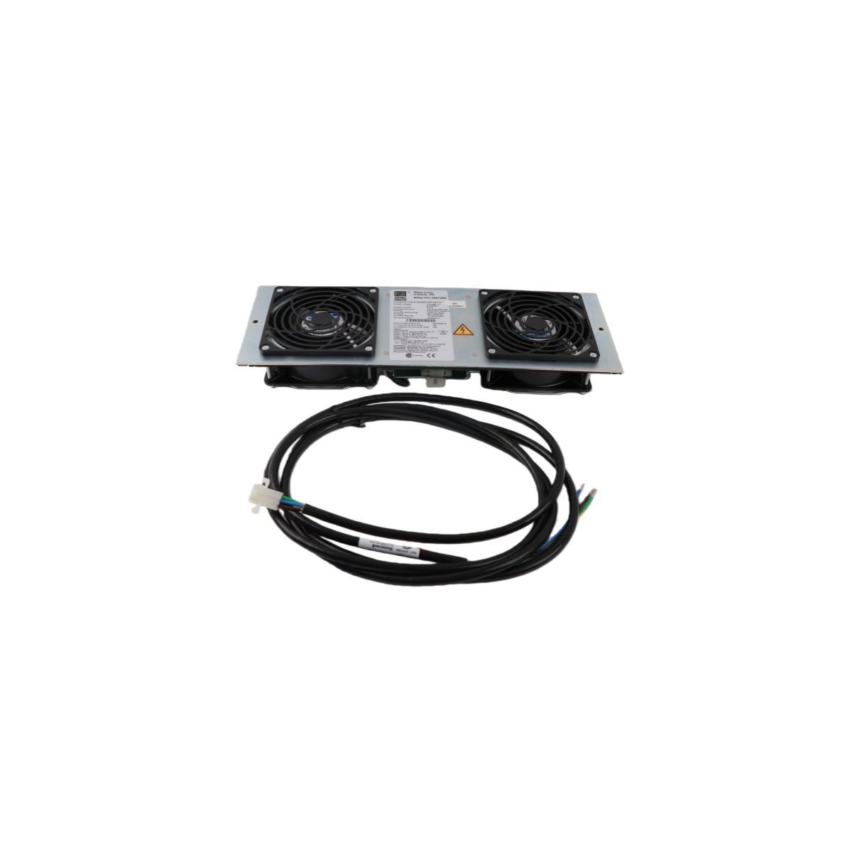
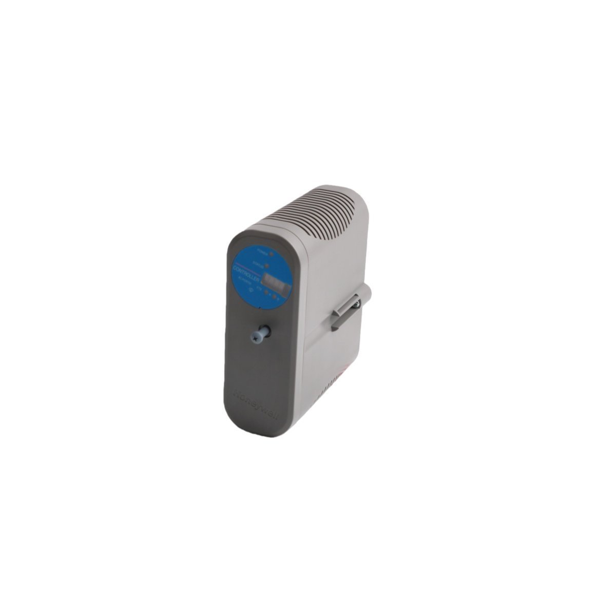
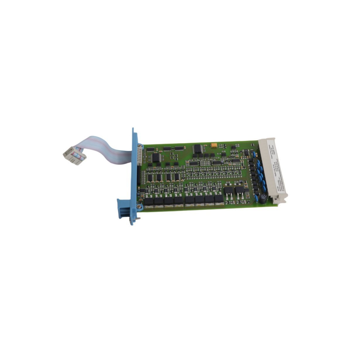
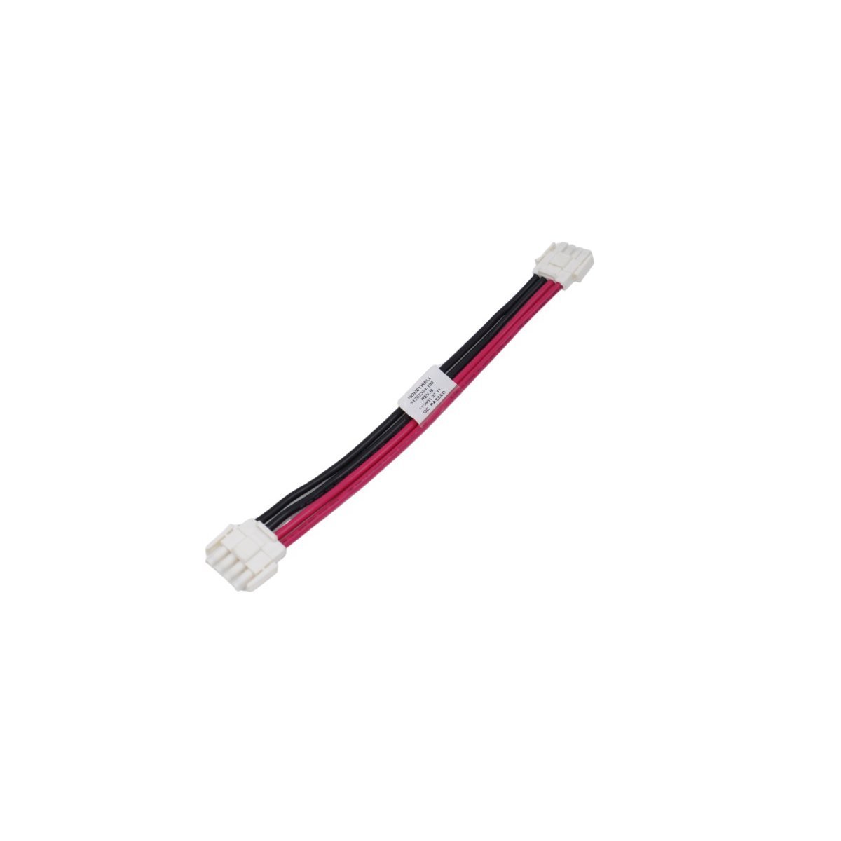
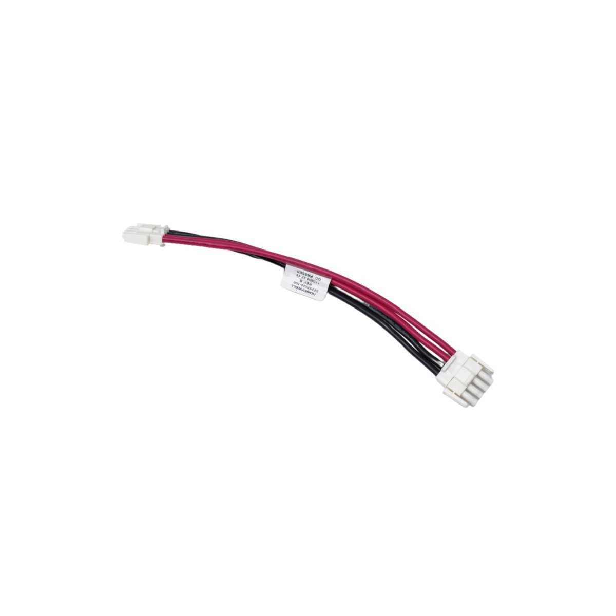
Honeywell 51199946-100 Series C Power System Battery Kit
Genuine Honeywell 51199946-100 Battery Kit for Experion PKS Series C power systems. Provides continuous runtime database protection and control memory backup.
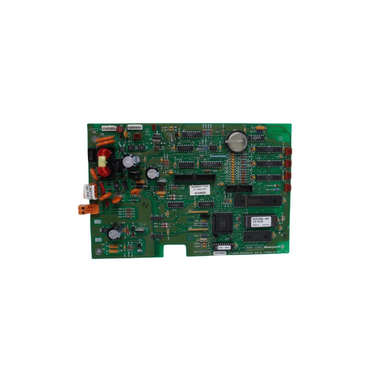
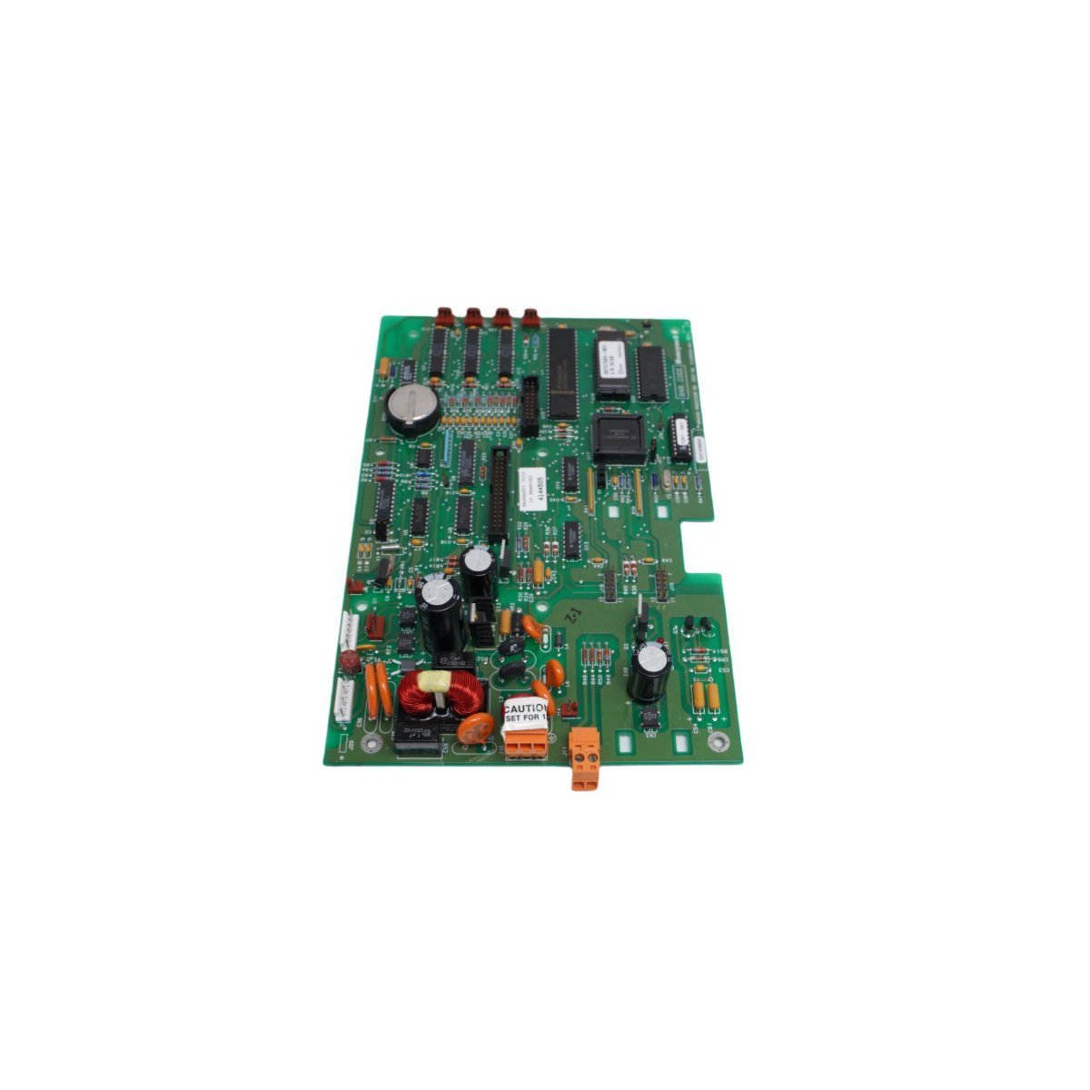
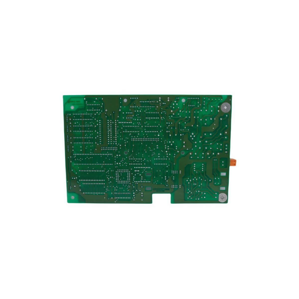
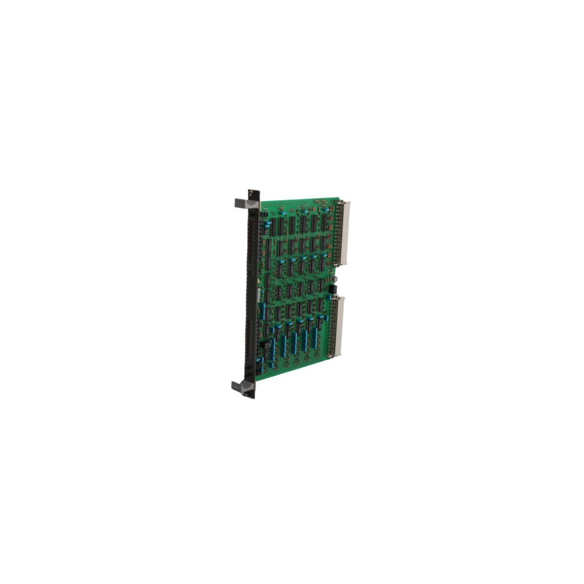
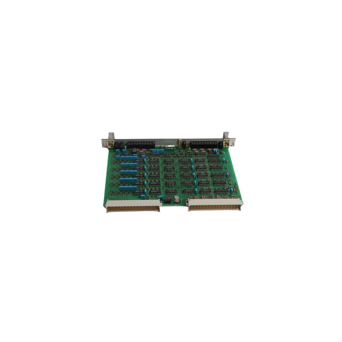
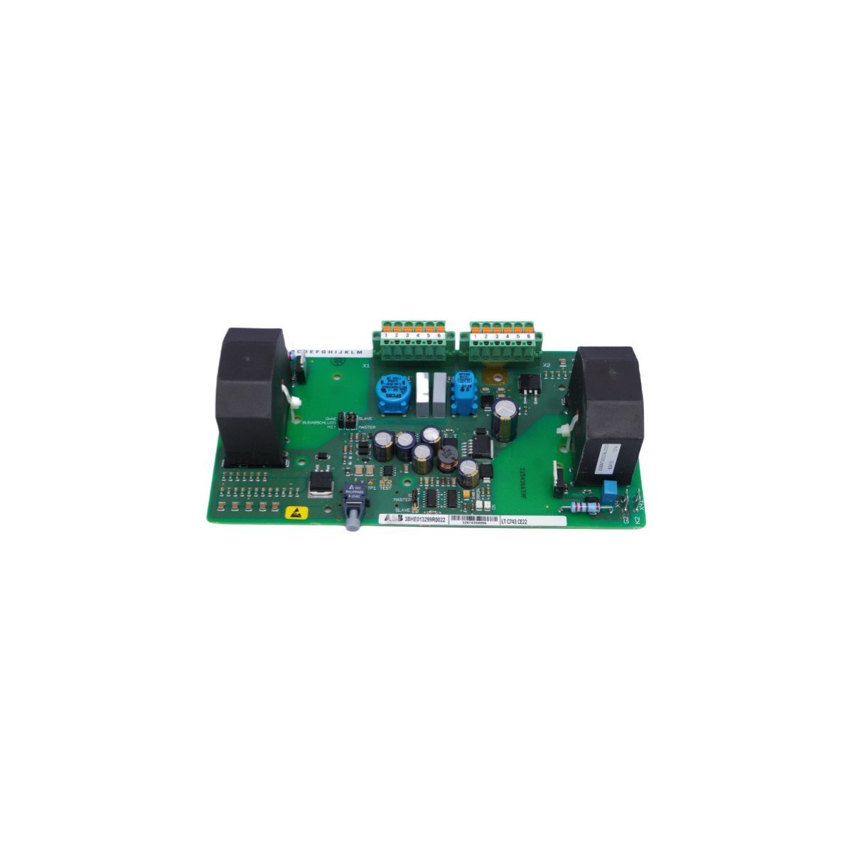
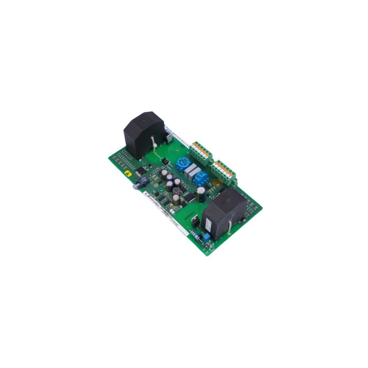
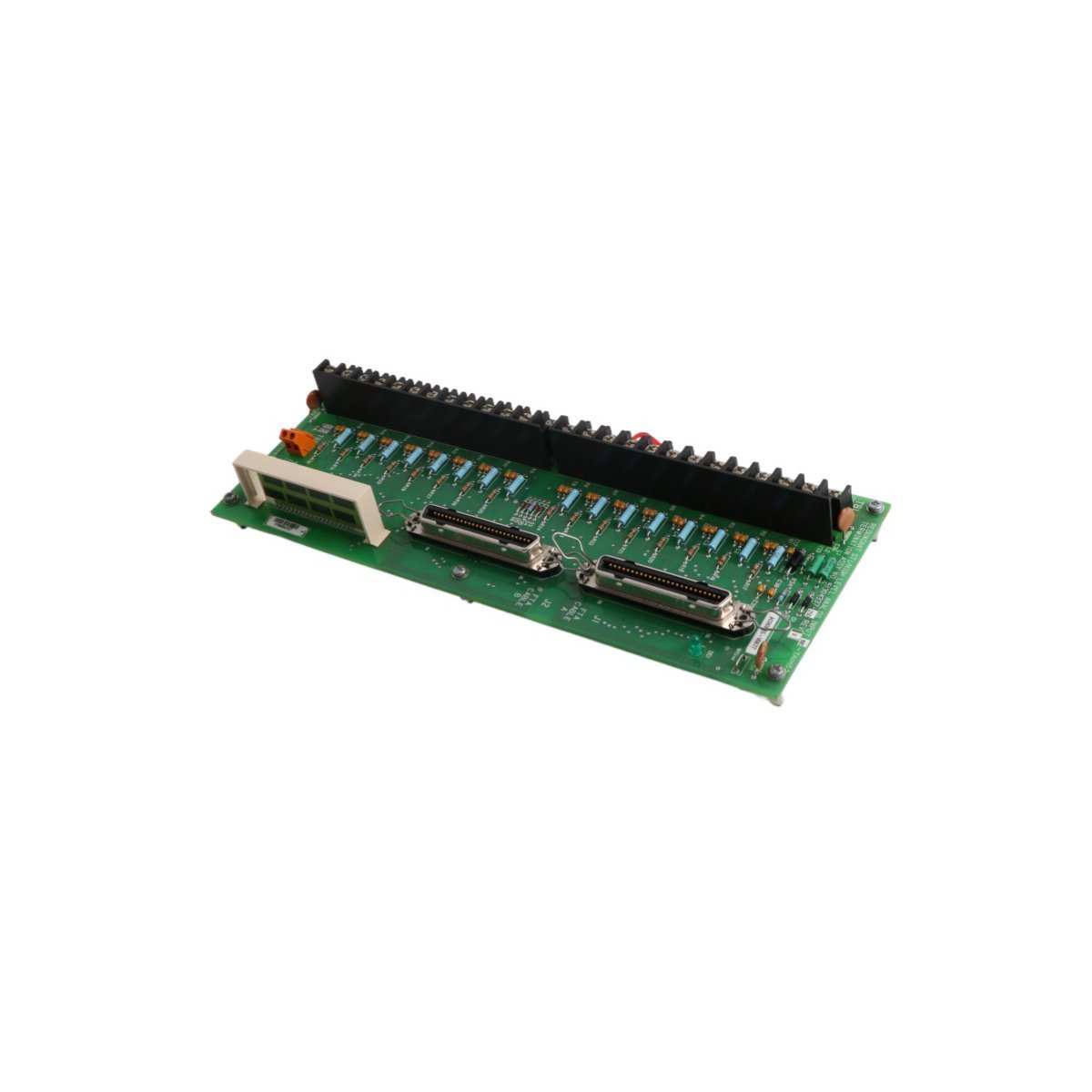
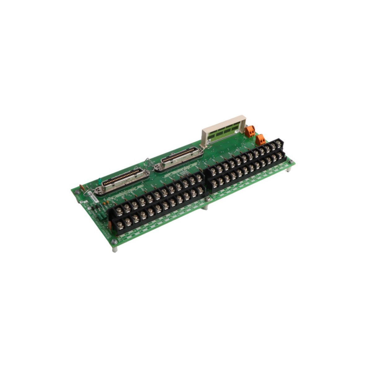
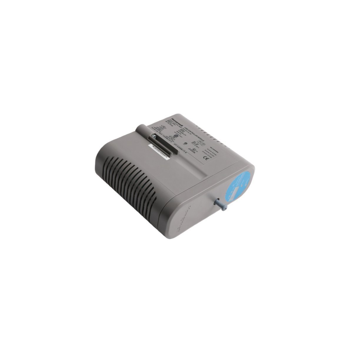
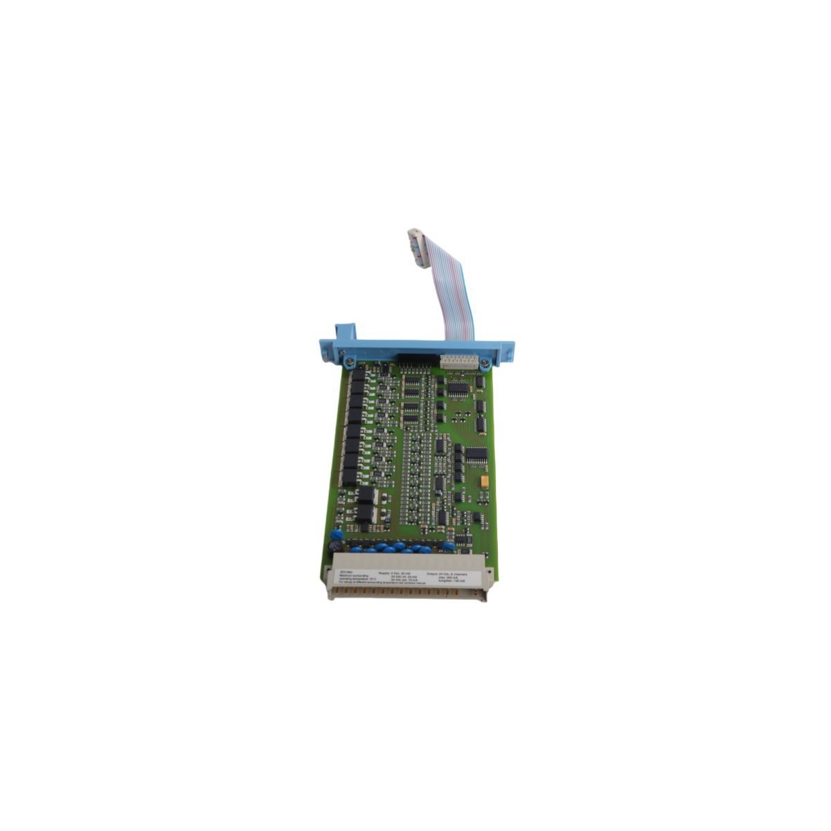
The Honeywell 51309355-001, also cataloged as the 51309355-001 Circuit Board, operates as a dedicated hardware component for signal processing and data routing within Experion PKS DCS platforms.
| Parameter | Specification |
|---|---|
| Model | 51309355-001 |
| Brand | Honeywell |
| Origin | USA |
| Weight | 0.3 kg |
| Dimensions | 26.5 cm x 16.2 cm x 4 cm |
| Operating Temp | Consult system environmental specs |
| Power Consumption | Not applicable (Passive backplane component) |
| System | DCS (Experion PKS) |
This circuit board facilitates data transmission across the control network, supporting standardized communication protocols within the Experion PKS architecture. It is engineered to maintain signal integrity through impedance-controlled paths, ensuring low-latency data exchange between I/O modules and the controller. The design incorporates channel-to-channel isolation to prevent electrical noise coupling, which is critical for maintaining the accuracy of 4-20 mA HART loop protocol signals when integrated with field instrumentation.
Q: Does this circuit board support hot-swap functionality within the I/O chassis?
A: Yes, the 51309355-001 is designed for hot-swap operations. However, ensure the controller is configured to recognize the module removal to prevent diagnostic alarms or unexpected process interruptions during the transition.
Q: What is the recommended practice for verifying board health during system maintenance?
A: Utilize the Experion PKS diagnostic software to poll the module status register. A green LED status on the board indicates successful communication with the backplane bus, while red or amber indicators suggest a fault in logic or power rails.








We are committed to protecting your privacy. The information collected here is strictly used to provide the requested quotes, technical support, and relevant industrial automation solutions.