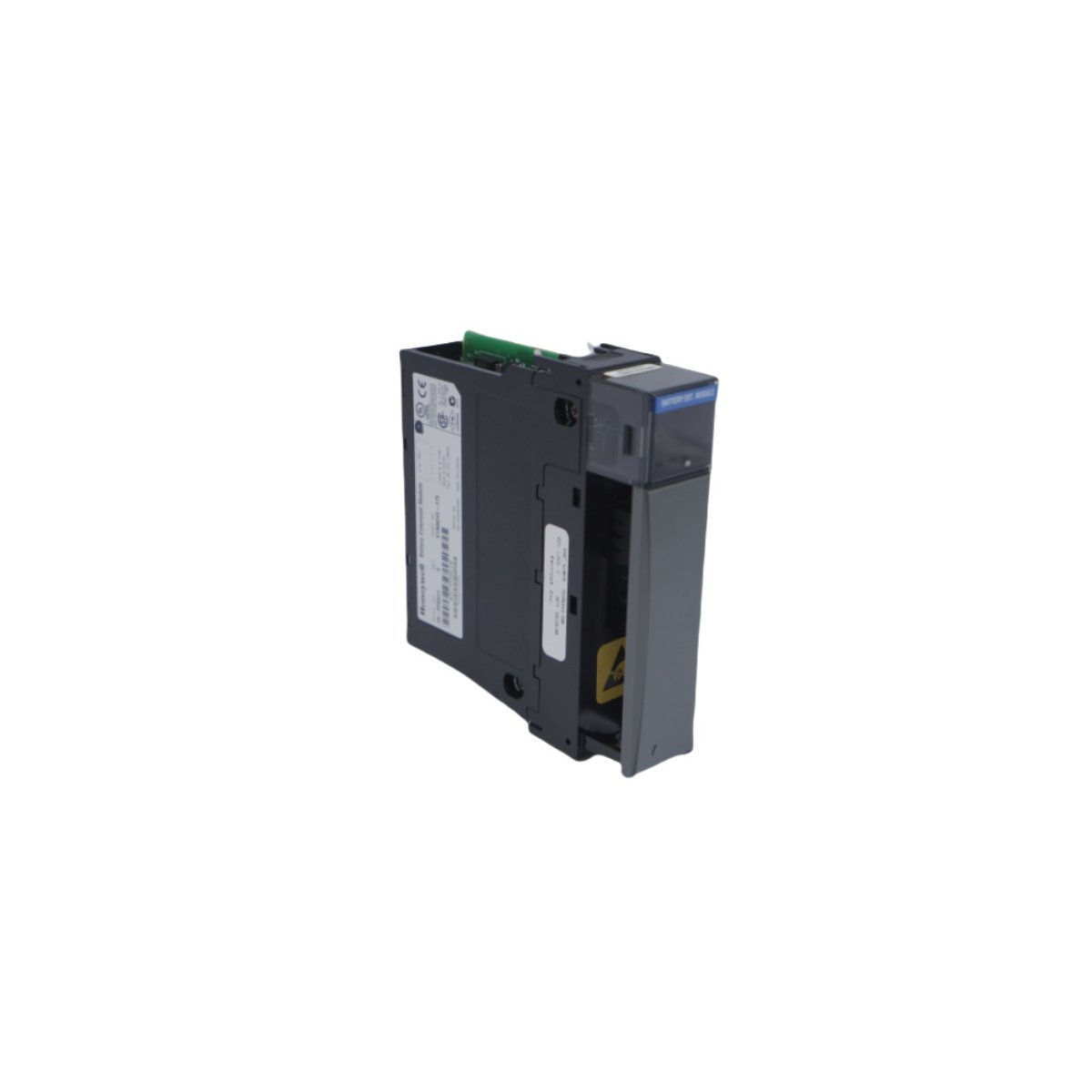
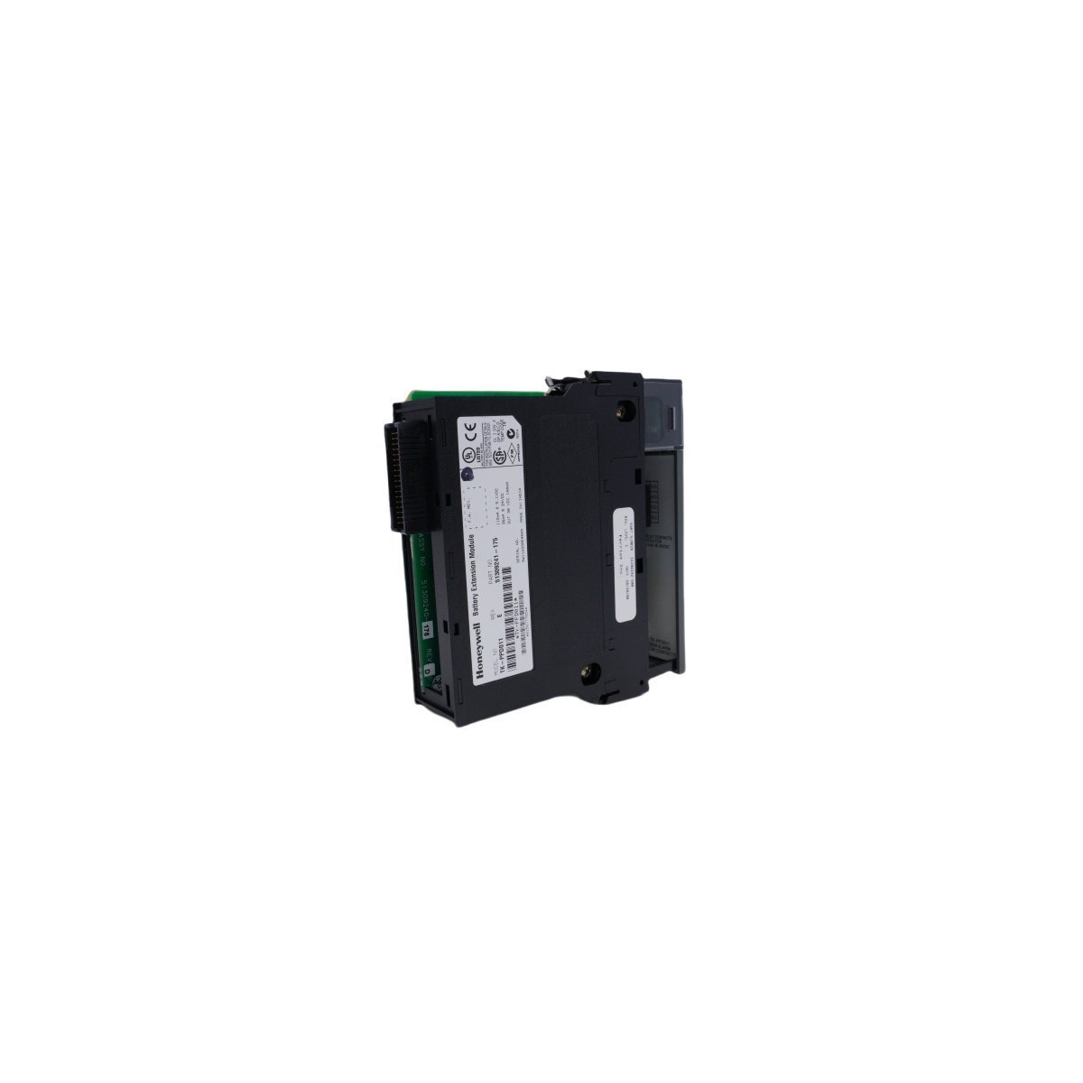
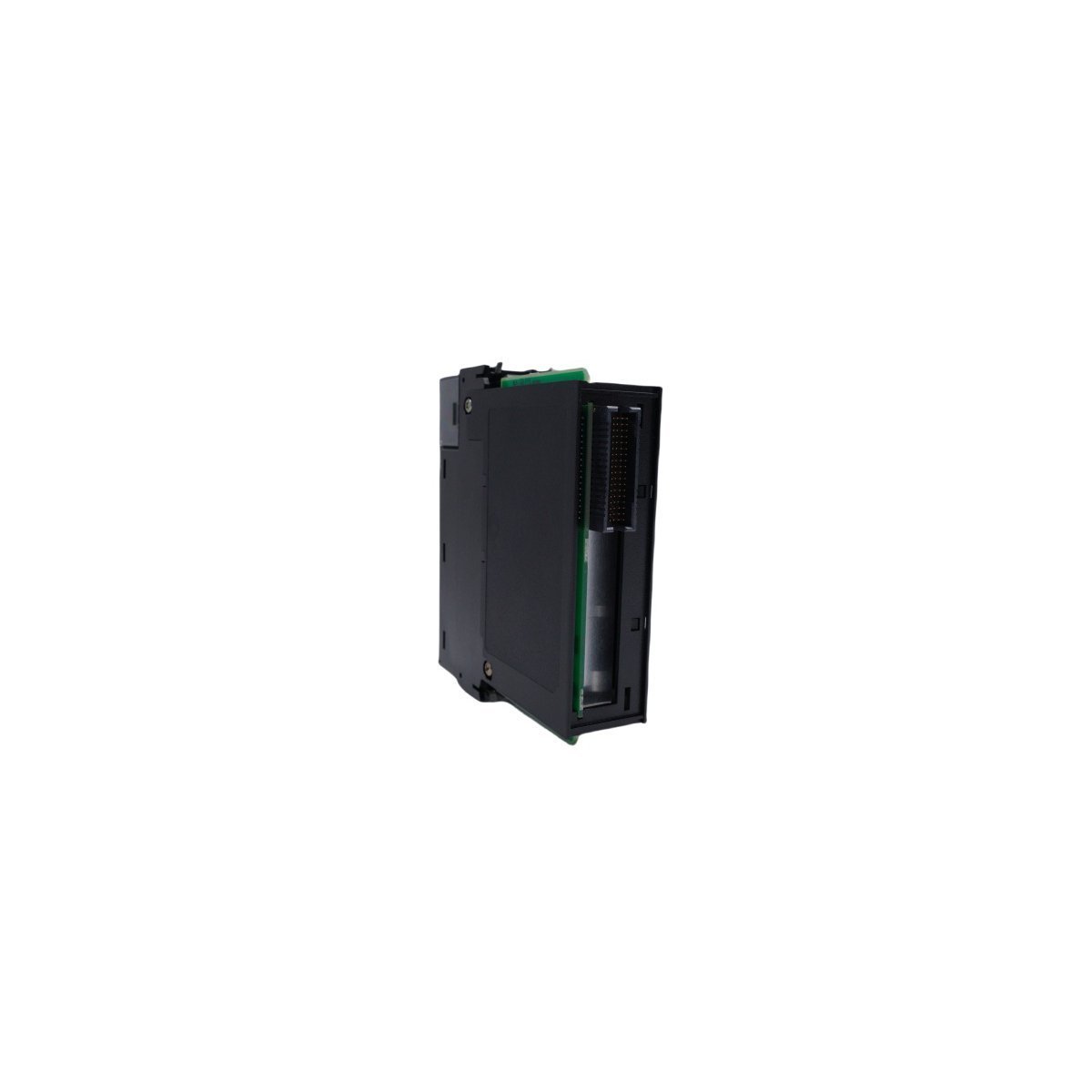
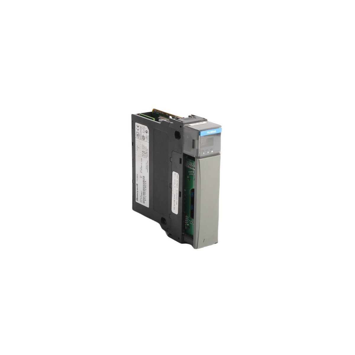
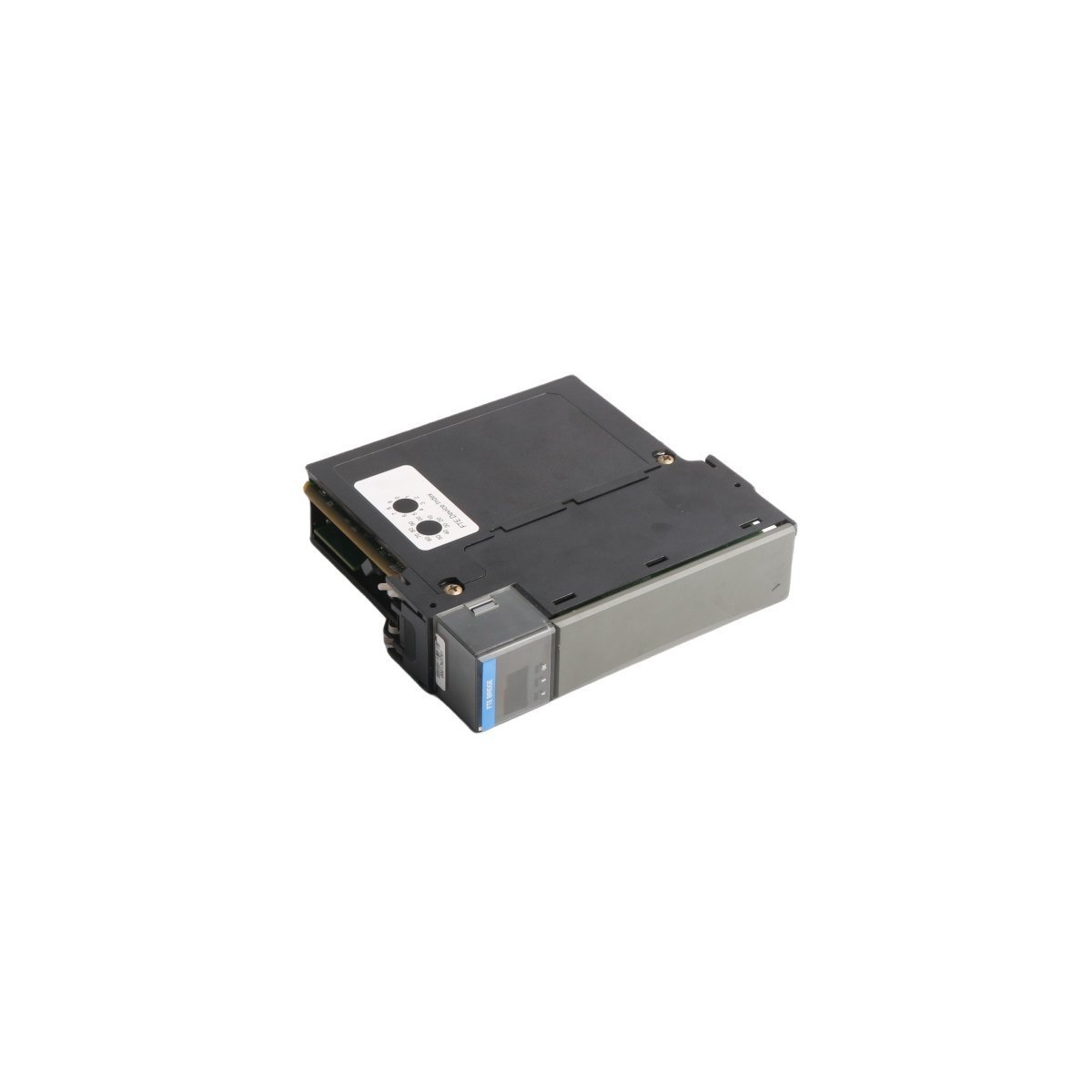
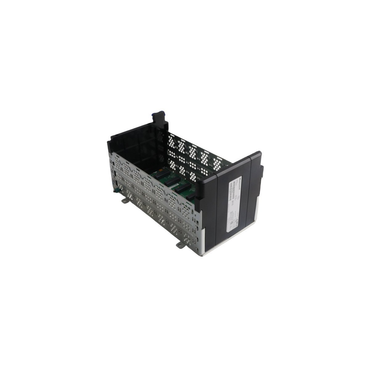
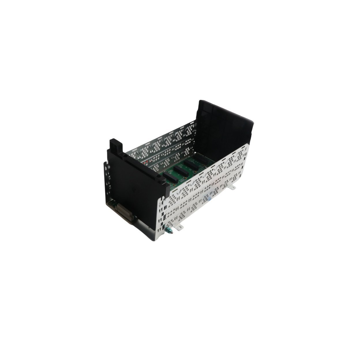
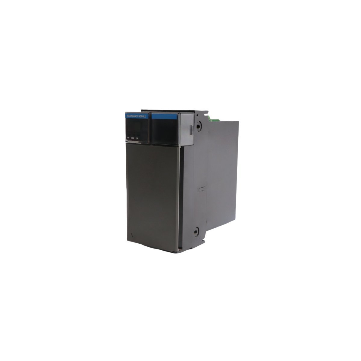
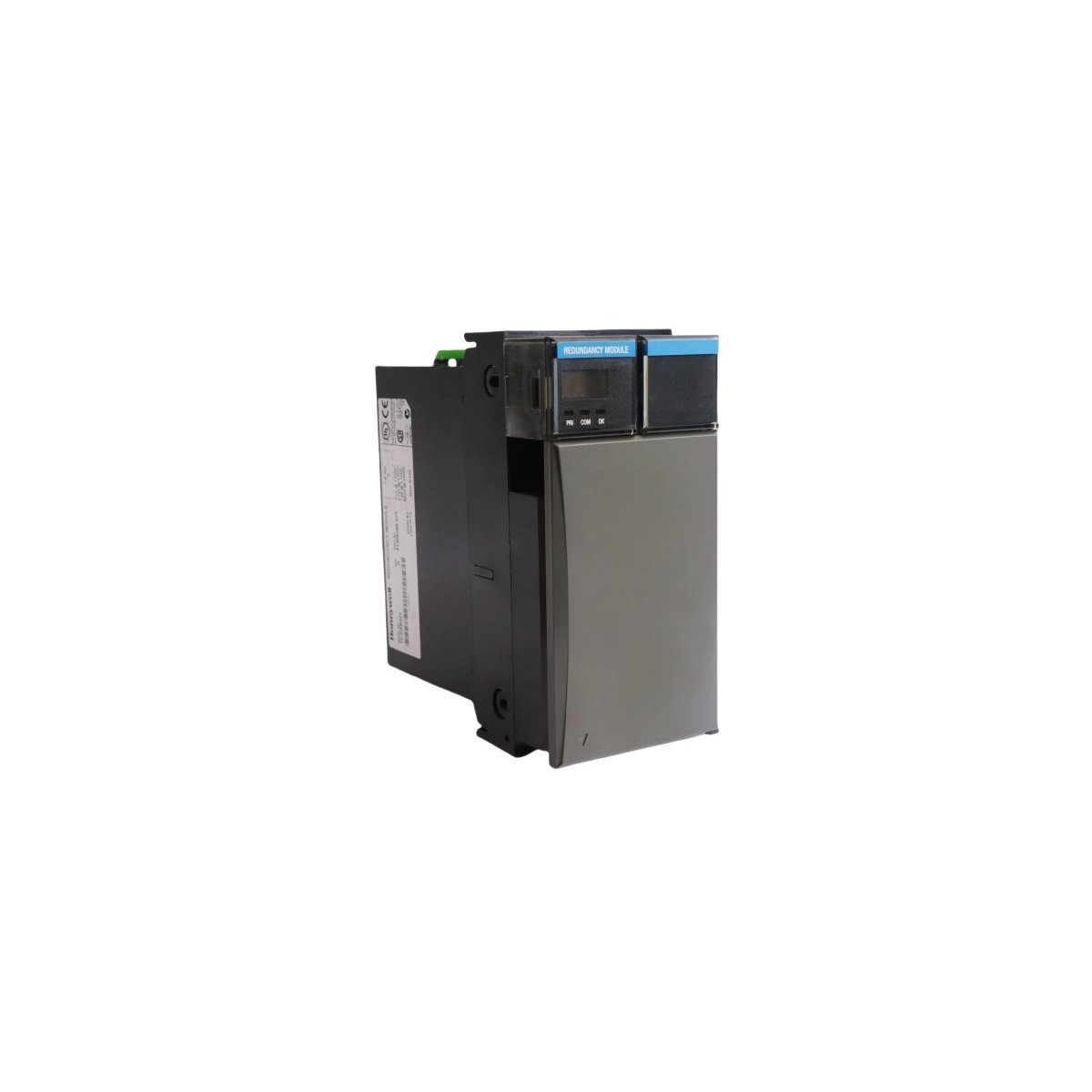
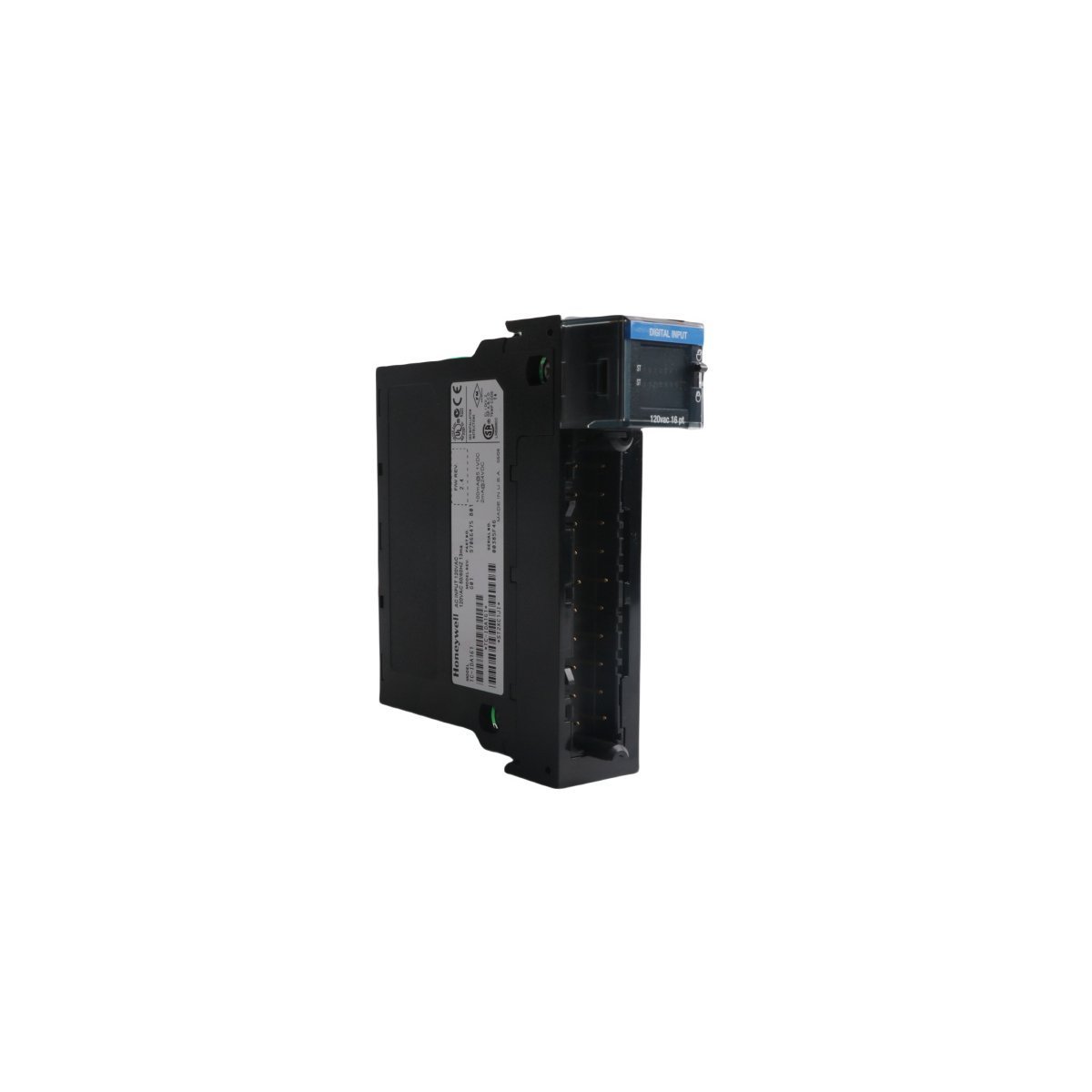
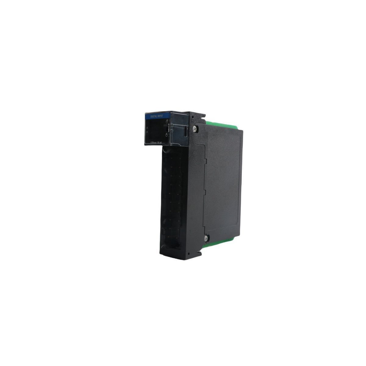
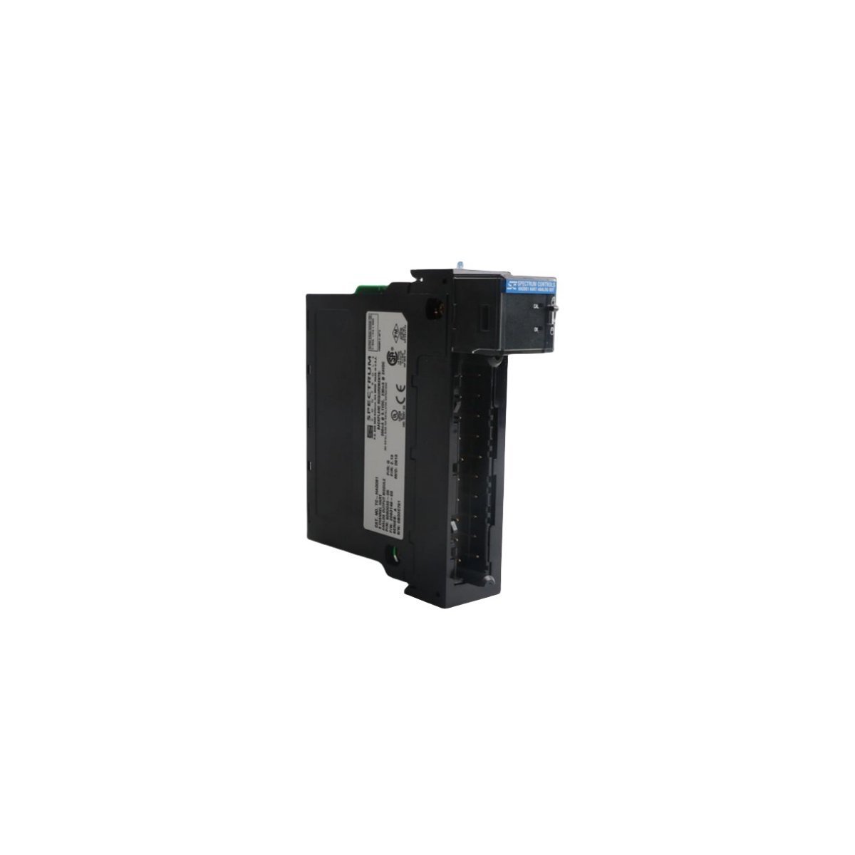
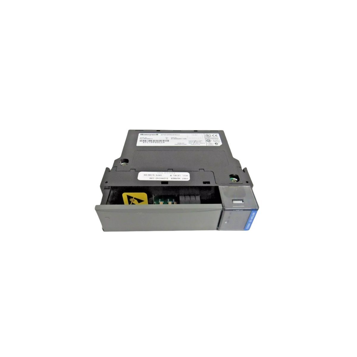
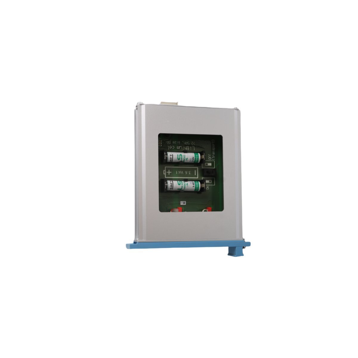
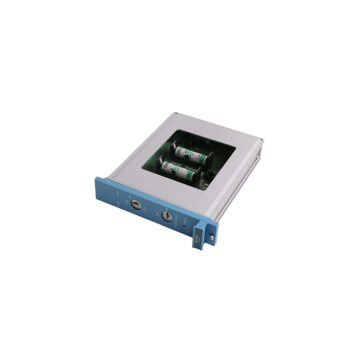
Configured for volatile memory power retention in Honeywell Experion LS DCS nodes, the Honeywell TK-PPD011 51309241-175 (TK-PPD011 51309241-175 Battery Extension Module) provides direct physical/electrical execution.
Hardware Specifications
Parameter
Specification
Model
TK-PPD011 51309241-175
Brand
Honeywell
Origin
USA
Weight
0.36 kg
Dimensions
3.5 cm x 14 cm x 14.5 cm
Operating Temp
0 to 60 deg C
Power Consumption
Backplane Auxiliary Battery Bus
Product Series
Experion LS
Module Type
Battery Extension Module
System
DCS
Status
Active
HS Code
8537101190
Process Isolation and HART Loop Interface Protocols
The TK-PPD011 51309241-175 maintains energy delivery to local volatile RAM memory circuits during main backplane power failure events, securing system configuration state parameters and real-time execution data. Built-in channel-to-channel isolation architecture protects auxiliary power lines from external noise injection across the internal DCS backplane.
Integrated power conditioning circuitry ensures clean supply delivery to backplane memory circuits. Built-in cold junction compensation (CJC) algorithms maintain voltage output regulation within calibrated limits across standard operating temperature ranges.
Frequently Asked Questions
Q: What primary function does the TK-PPD011 51309241-175 fulfill during a backplane power loss?
A: The module supplies dedicated battery auxiliary power directly to system memory backplane rails to prevent loss of volatile controller database and state data.
Q: Can the TK-PPD011 51309241-175 module be hot-swapped while the rack is energized?
A: Hot-swapping must comply with system enclosure safety guidelines and live-maintenance restrictions to avoid transient discharge into adjacent backplane buses.
Field Installation Guidelines
First and foremost, disconnect main supply voltage and confirm complete de-energization of the target DCS enclosure prior to handling auxiliary battery equipment.
Next, inspect the module mechanical alignment channels and slide the TK-PPD011 51309241-175 into the backplane chassis guide slots until the terminal interface locks securely.
Subsequently, torque all mechanical retaining fasteners to ensure proper grounding contact and physical retention against vibration.
Following hardware securing, route auxiliary power cables through designated, isolated wiring raceways to prevent cross-coupling with high-voltage AC lines.
Finally, energize the rack assembly and verify status LEDs to confirm continuous power delivery and healthy memory subsystem operation.
The Honeywell TC-FTEB01 (51309512-125) is an active Ethernet communication module designed for the Experion LS Distributed Control System, providing high-speed routing and scalable connectivity for industrial automation.
The Honeywell TC-FXX072 (97126485) is a high-density rack module for Experion LS DCS, providing stable mounting and reliable connectivity for industrial I/O configurations.
The Honeywell TC-PRR021 (51309288-225) is a high-availability redundancy module designed for the Experion LS DCS. It enables seamless hot-standby failover between control processors, ensuring zero process interruption and high system uptime in critical industrial automation environments.
The Honeywell TK-OAV061 (97178272) is a precision Analog Output Module for Experion LS systems.It provides reliable 4-20 mA signal control for valves and actuators. This Series C component features onboard diagnostics and high-channel isolation for process stability.
The Honeywell TC-IDA161 97066475 is a 16-point digital input module for Experion LS systems. It provides 24V DC discrete signal acquisition with robust isolation and real-time status diagnostics.
The Honeywell TC-PPD011 51309241-125 is a high-performance battery extension module for the Experion LS DCS.It provides essential power redundancy for controllers, featuring a wide -20°C to +60°C temperature range and efficient energy management to ensure uninterrupted industrial operations.
The Honeywell TK-FFIF01 51403420-275 is a FOUNDATION Fieldbus Interface Module for Experion LS systems. It streamlines field device communication, reduces wiring complexity, and provides advanced diagnostics for industrial DCS applications.
The Honeywell TC-PCIC02 93404872 is a high-performance ControlNet interface module for Experion LS systems. It provides deterministic 5Mbps communication, supports media redundancy, and ensures seamless real-time data exchange between controllers and remote I/O in DCS environments.
The Honeywell TC-IXR061 (96978377) is a 6-channel galvanically isolated analog input module designed for the Experion PKS system.It provides high-precision data acquisition with built-in open-wire detection and robust RFI immunity for demanding industrial process control.
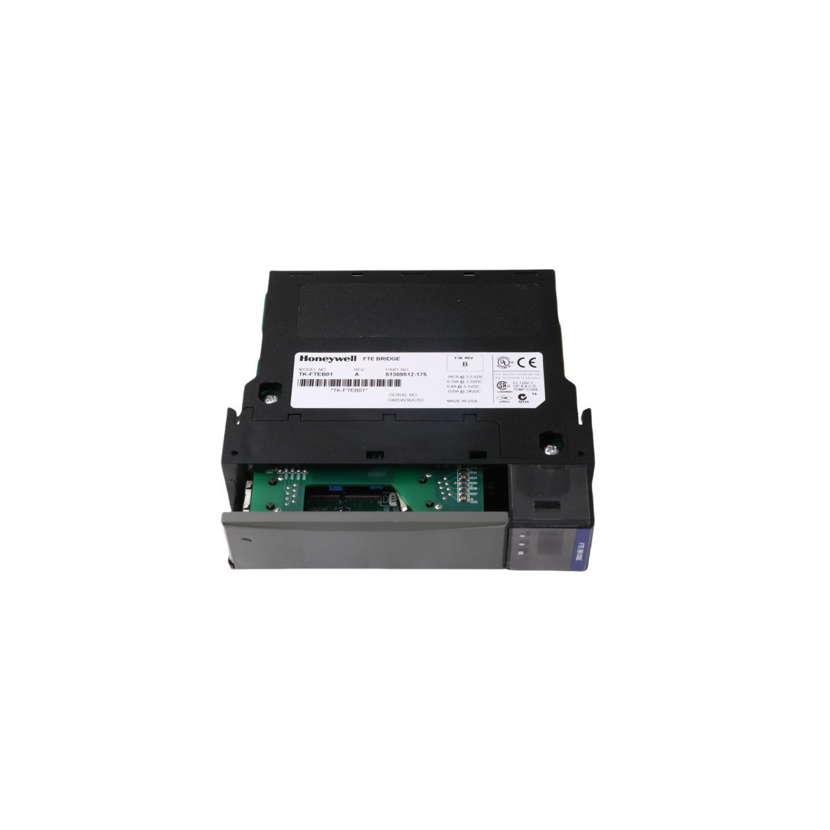
The Honeywell TK-FTEB01 (51309512-175) is a high-performance Ethernet Bridge for Experion PKS C300 systems. It provides redundant Fault Tolerant Ethernet (FTE) connectivity and advanced network filtering to ensure secure, high-speed communication between controllers and supervisory networks.
The Honeywell TC-OAV081 (97062779) is an 8-channel analog output module designed for the Experion PKS system. Featuring 4-20 mA current loop support and 12-bit resolution, this module delivers precise control for valves, drives, and actuators in safety-critical industrial environments.
The Honeywell FC-BKM-0001 is a dedicated Battery Switch Module designed for Safety Manager and FSC systems.It ensures continuous memory retention and real-time clock operation by managing the transition to backup battery power, featuring integrated diagnostics and high-reliability switching for SIL-rated applications.
We are committed to protecting your privacy. The information collected here is strictly used to provide the requested quotes, technical support, and relevant industrial automation solutions.