


Sale!
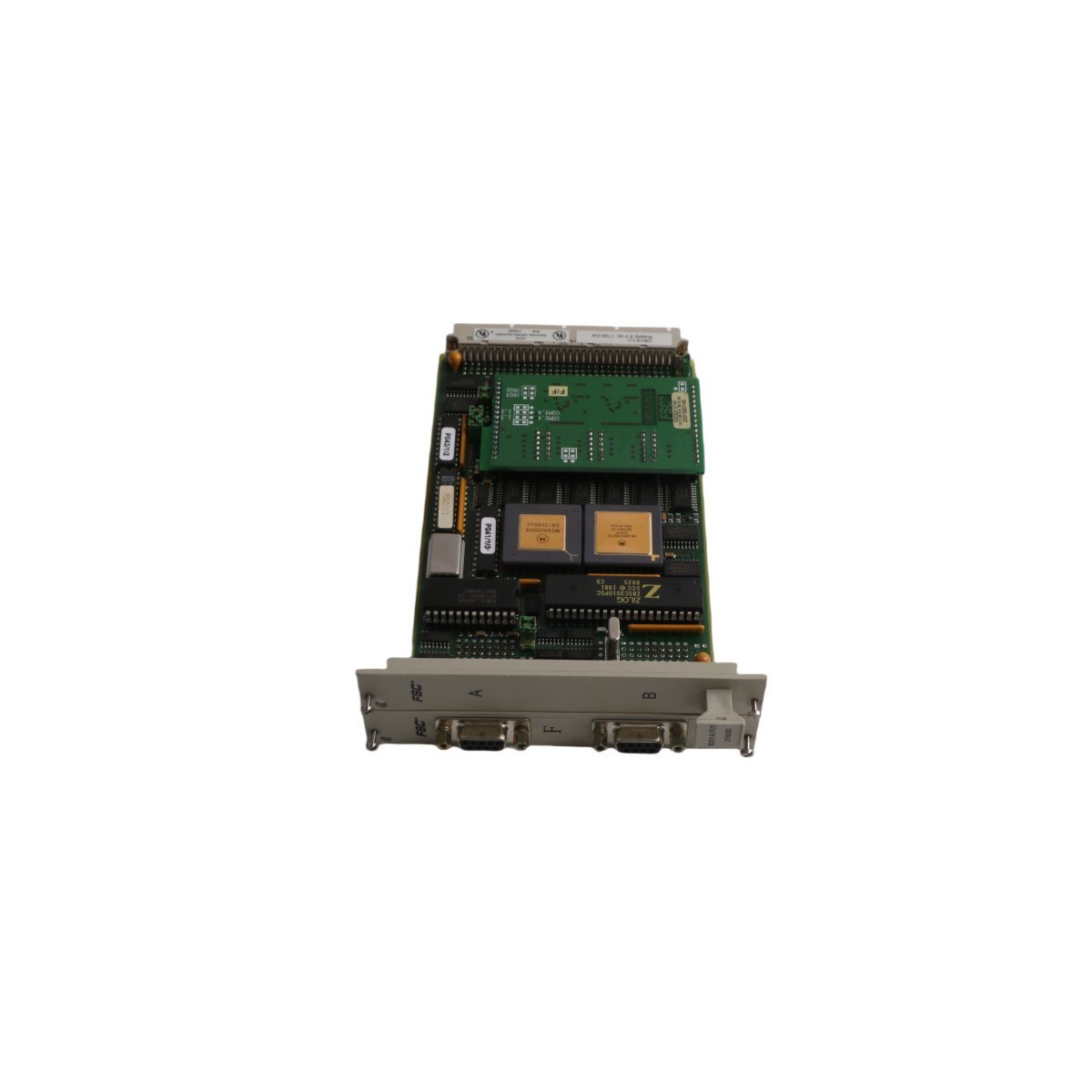
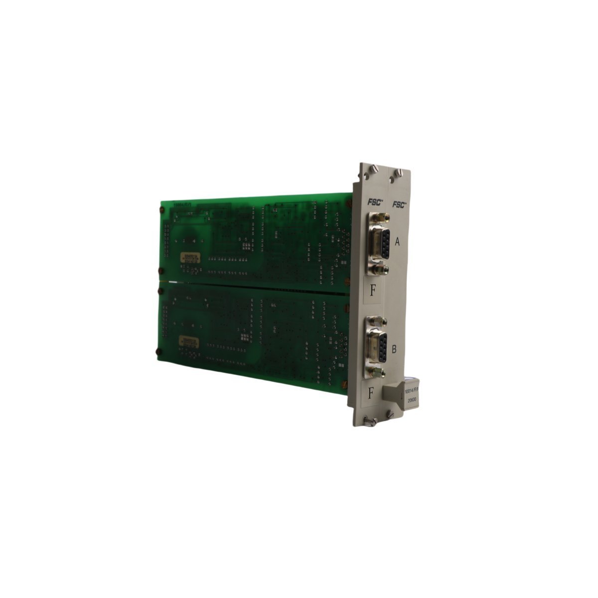
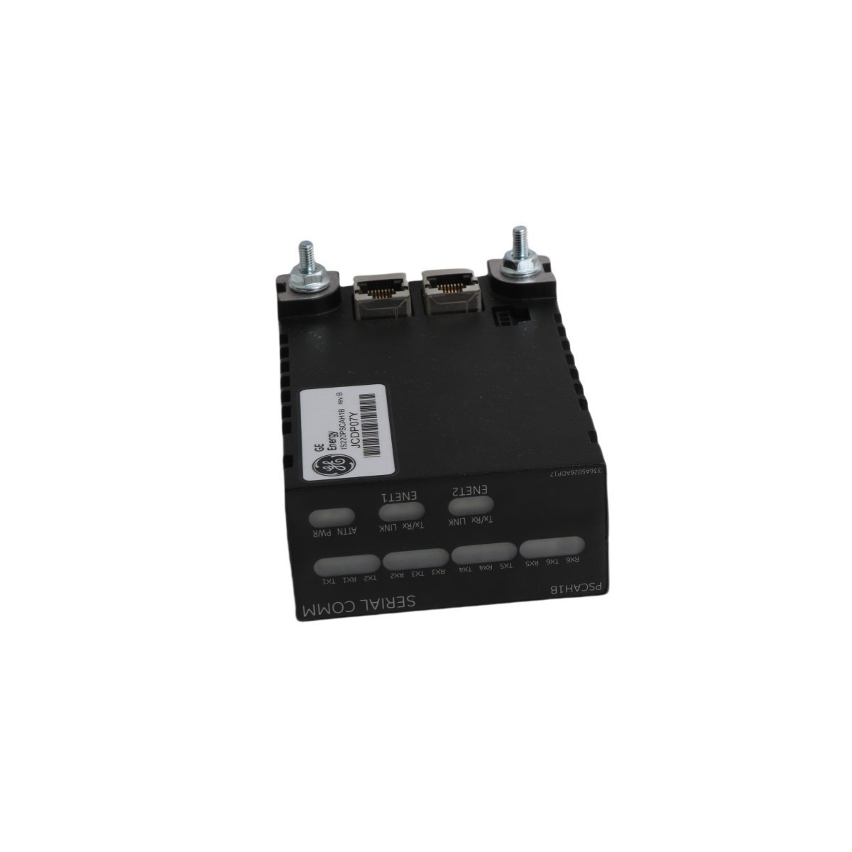
Honeywell 10014/F/F Dual Port Communication Module
The Honeywell 10014/F/F is a dual-port communication module designed for FSC safety systems, providing reliable Ethernet connectivity and robust diagnostic monitoring.
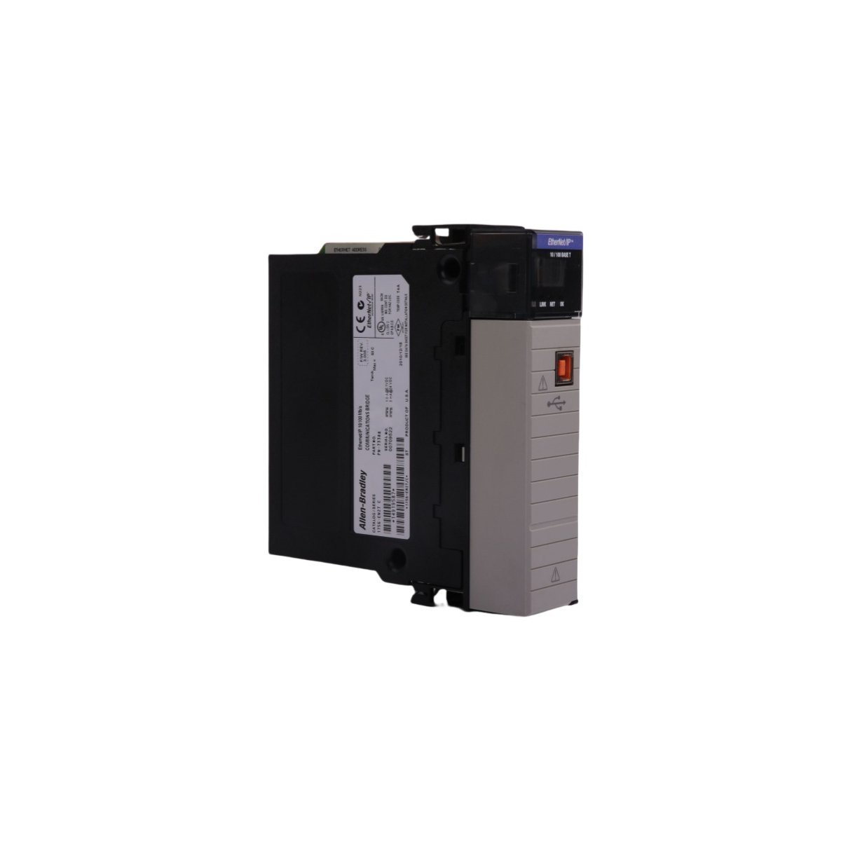
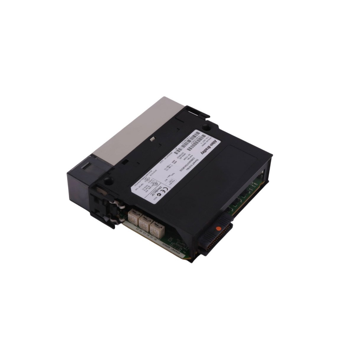
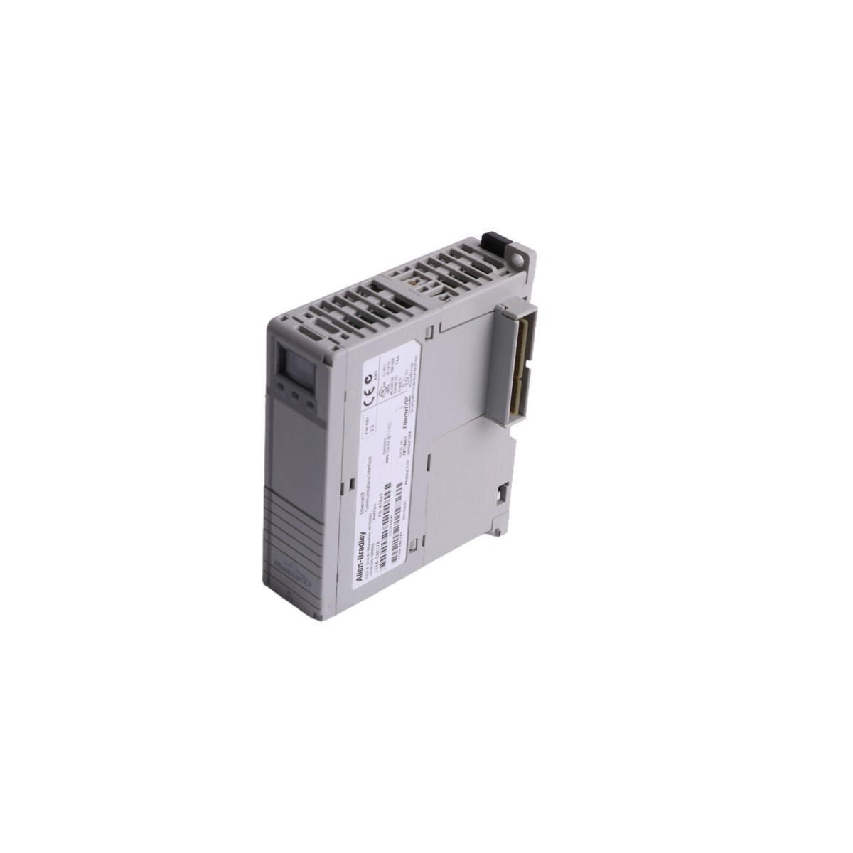
Allen-Bradley 1756-DHRIO ControlLogix network interface card supporting Data Highway Plus and Remote I/O legacy networks. Brand new original stock, fully tested with global logistics.
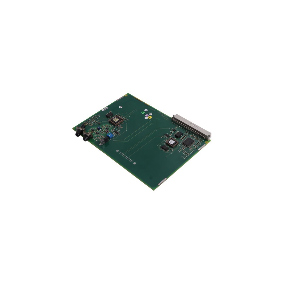
The Allen-Bradley 1756-DHRIO is a dual-channel Data Highway Plus (DH+) and Universal Remote I/O (RIO) scanner module belonging to the ControlLogix® 1756 platform. It functions as an intelligent network bridge, allowing high-speed ControlLogix processors to exchange peer-to-peer messages over legacy DH+ networks or control remote I/O chassis, blocks, and motor control centers (MCCs) over legacy RIO links.
| Parameter | Specification |
|---|---|
| Model Number | 1756-DHRIO |
| Manufacturer | Allen-Bradley / Rockwell Automation |
| Module Type | Network Communication Module |
| Protocols Supported | Data Highway Plus (DH+), Universal Remote I/O (RIO) |
| Number of Channels | 2 independent networks (Configured via rotary switches) |
| Baud Rates | 57.6 Kbaud, 115.2 Kbaud, 230.4 Kbaud |
| Backplane Current (5V) | 1.7 mA |
| Backplane Current (24V) | 850 mA |
| Power & Thermal Dissipation | 4.5 W Maximum / 15.4 BTU/hr |
| Physical Weight | 0.28 kg (0.63 lbs) |
| Physical Dimensions | 12.5 x 25.0 x 27.5 cm (Standard Single-Slot Module) |
| HS Code | 8537101190 |
Note on Data Variations: While certain logistics manifests report shipping/carton weights near 5.9 kg due to bulk master-pack handling, the standalone physical module weight is 0.28 kg (0.63 lbs).
When configured for DH+, the module functions as a peer-to-peer routing terminal. It transfers programming tokens and application messaging (MSG instructions) between ControlLogix controller paths and older PLC-5®, SLC™ 500, or legacy HMI networks.
When acting as a Remote I/O scanner, the module scans discrete and analog data from remote adapters (such as a 1771-ASB or 1747-ASB) without passing through an intermediate controller. It updates local processor tags synchronously over the ControlLogix backplane.


We are committed to protecting your privacy. The information collected here is strictly used to provide the requested quotes, technical support, and relevant industrial automation solutions.