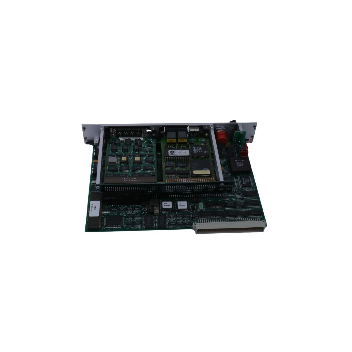
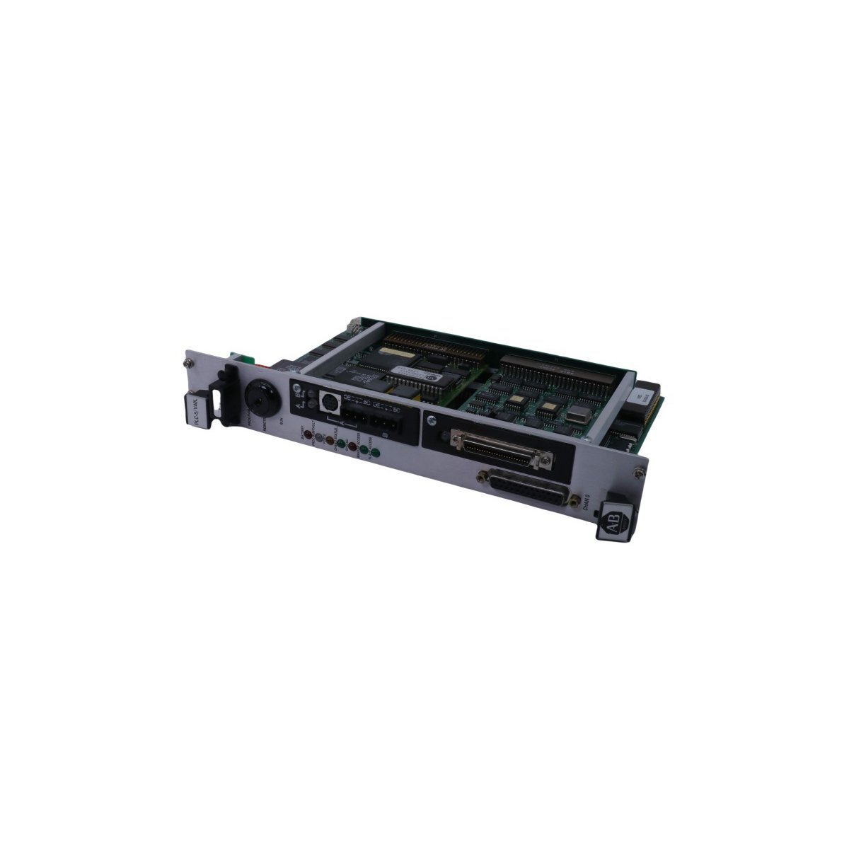
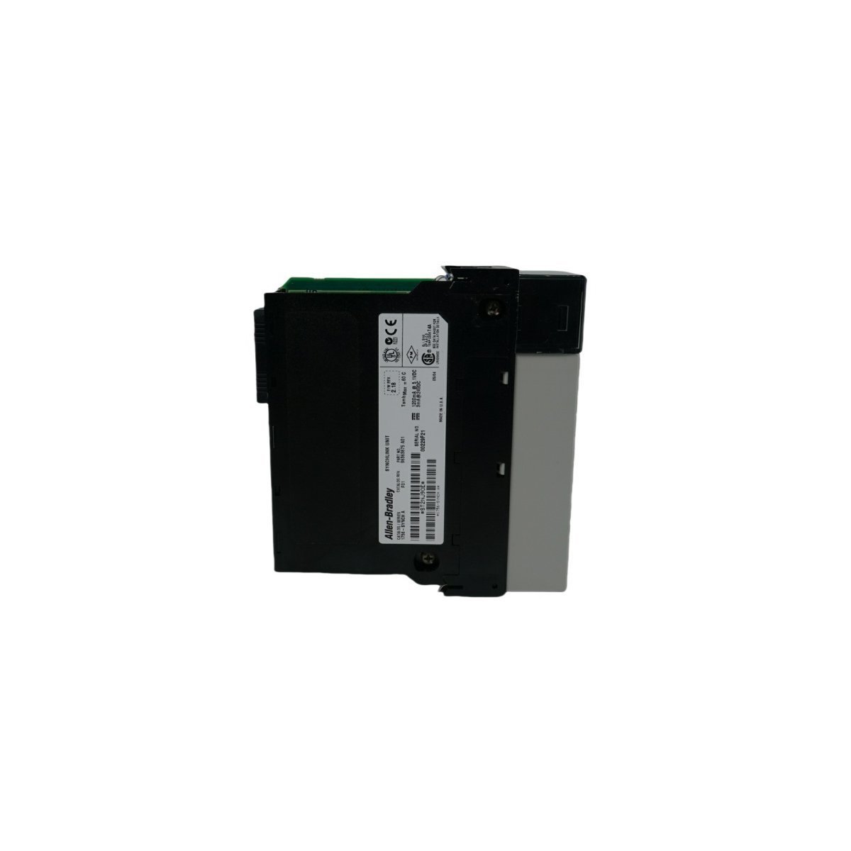
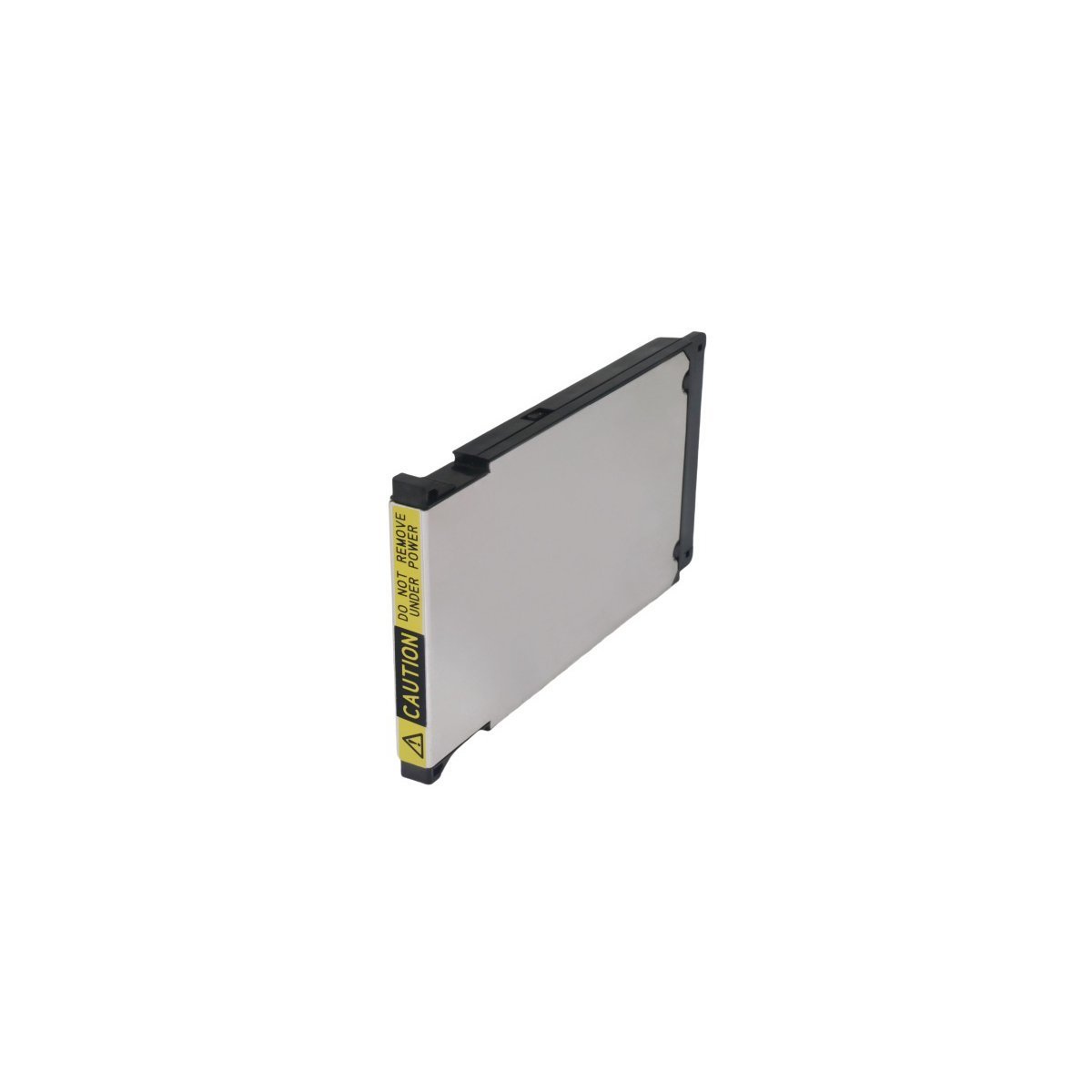
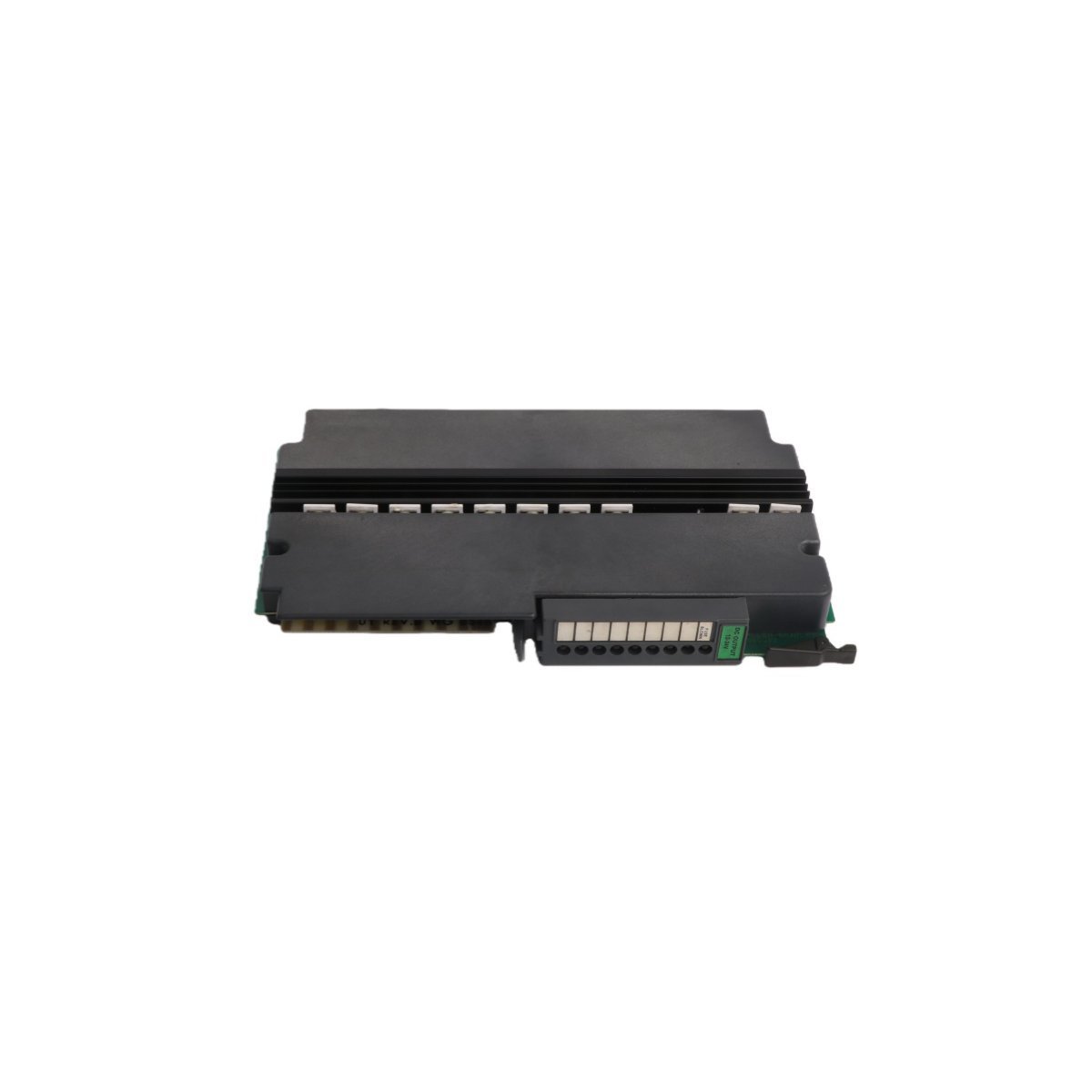
You are here:
SKU: 1771-OW

Allen-Bradley 1771-OW PLC-5 Series

The Allen-Bradley 1771-OW is an 8-channel electromechanical relay output module engineered for the classic PLC-5 architecture. Procure this factory-original surplus hardware in brand new condition, backed by global logistics support and rapid transit options. Contact us now to secure your technical components.

The Allen-Bradley 1771-OW serves as the primary 1771-OW Selectable Contact Output Module utilized to execute physical contact closure operations across PLC-5 platforms. The hardware functions as an electromechanical switching interface, establishing direct isolated paths for external field loads using eight onboard relay channels partitioned into four distinct galvanic groups. It provides physical state modification for pilot lights, motor starters, and solenoid valves based on the logic state synchronized through the rack backplane.

Hardware Specifications

ParameterSpecification
Model1771-OW
BrandAllen-Bradley
OriginUSA
Weight0.9 kg
Dimensions3.5 x 13 x 14.5 cm
Operating Temp0 to +60 deg C
Power Consumption700 mA at 5 VDC maximum backplane load
Range of ProductPLC-5 / 1771 Universal I/O
SystemPLC
Module TypeSelectable Contact Output Module
Communication ServiceEthernet router compatible interface
HS CODE8537101190
Discontinued onJune 30, 2016
Configuration8 Output Channels (4 Isolated Groups of 2 Channels)
Voltage Switching Range24 to 138 VAC (Resistive) / 24 to 125 VDC
Continuous Current Rating1.0 A per channel (maximum)

Industrial Control & Drive Deterministic Networks

The module interfaces with supervisory processing architectures via the internal 1771 chassis bus, translating logic demands into coil excitation commands with minimal propagation delay. This framework enables predictable I/O density scaling alongside external serial or Profinet / EtherNet/IP deterministic networks via remote I/O adapter configuration modules. High-speed backplane communication velocity synchronization guarantees that the output contact relays align directly with the primary ladder execution cycles, while onboard firmware flash compatibility checks preserve hardware status flags across system restarts.

Frequently Asked Questions

Q: Can channels within the 1771-OW be mixed between normally open (NO) and normally closed (NC) configurations?

A: Yes. Each channel features onboard physical jumpers or selectable wire termination paths that permit independent configuration as either normally open or normally closed contacts prior to wiring installation.

Q: Is hot-swapping or RIUP (Removal and Insertion Under Power) supported for this module?

A: No. The 1771 universal I/O chassis architecture requires that power to the backplane and all field wiring arms be disconnected before extraction to avoid arc flash over or disruption of adjacent I/O communication.

Field Installation Guidelines

  1. Power down the 1771 I/O chassis and any external supply voltages routed to the field-side wiring arms before installation.
  2. Insert the plastic keying bands into the backplane connectors between pins 4 and 6, and pins 22 and 24 to prevent insertion of incorrect module types into the designated slot.
  3. Terminate load lines at the dedicated field wiring arm, grouping circuits to maintain strict isolation parameters between separate voltage sources.
  4. Install suppression networks (RC snubbers for AC loads, diodes for DC inductive loads) directly across all inductive field devices to suppress voltage transients and prolong electromechanical relay life.