You are here:
SKU: SDCS-AMC-DC-2 3ADT312700R0001

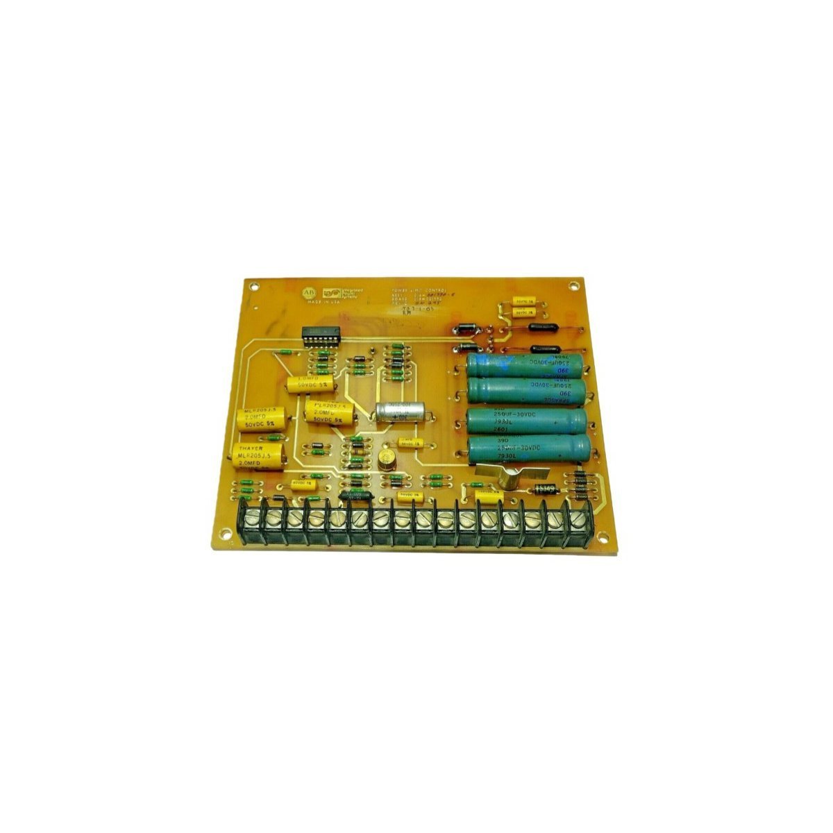
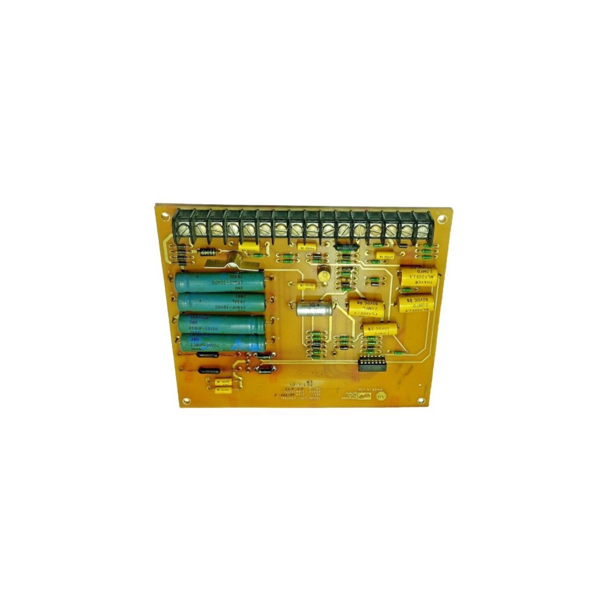
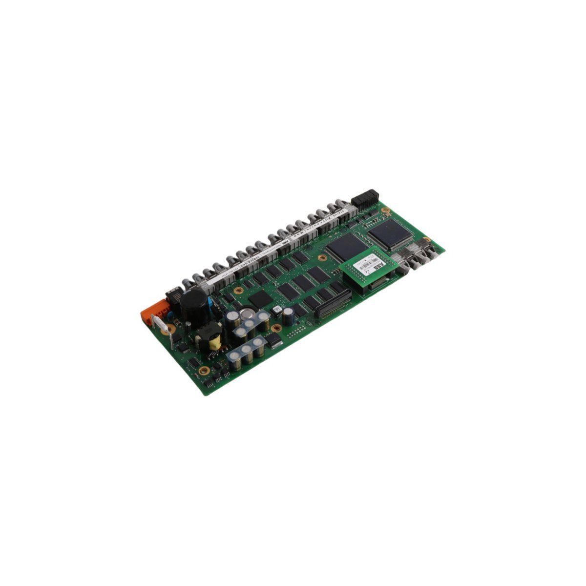
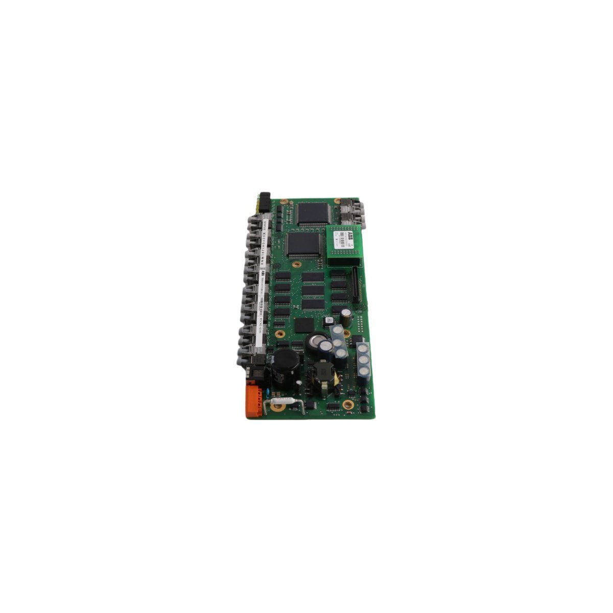
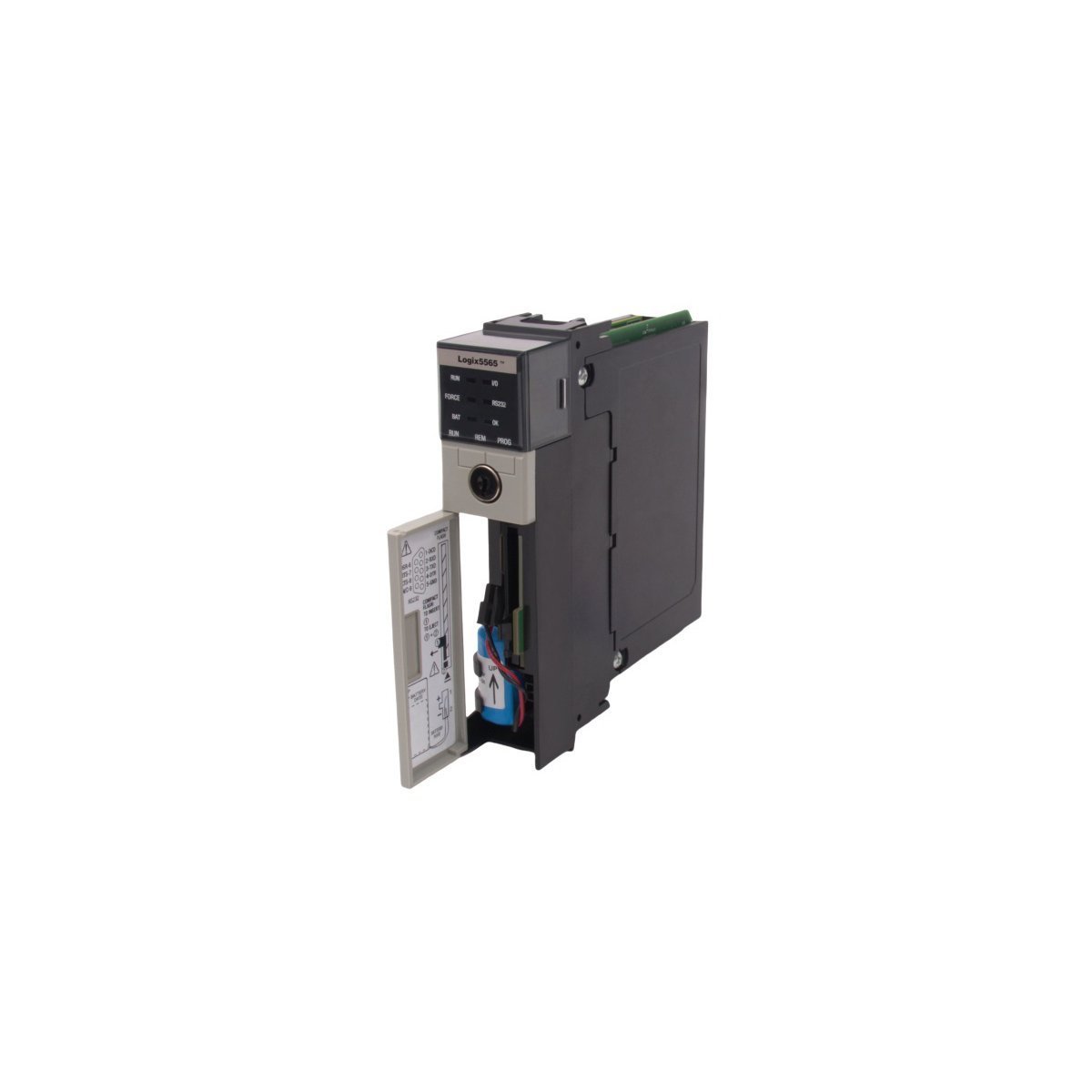
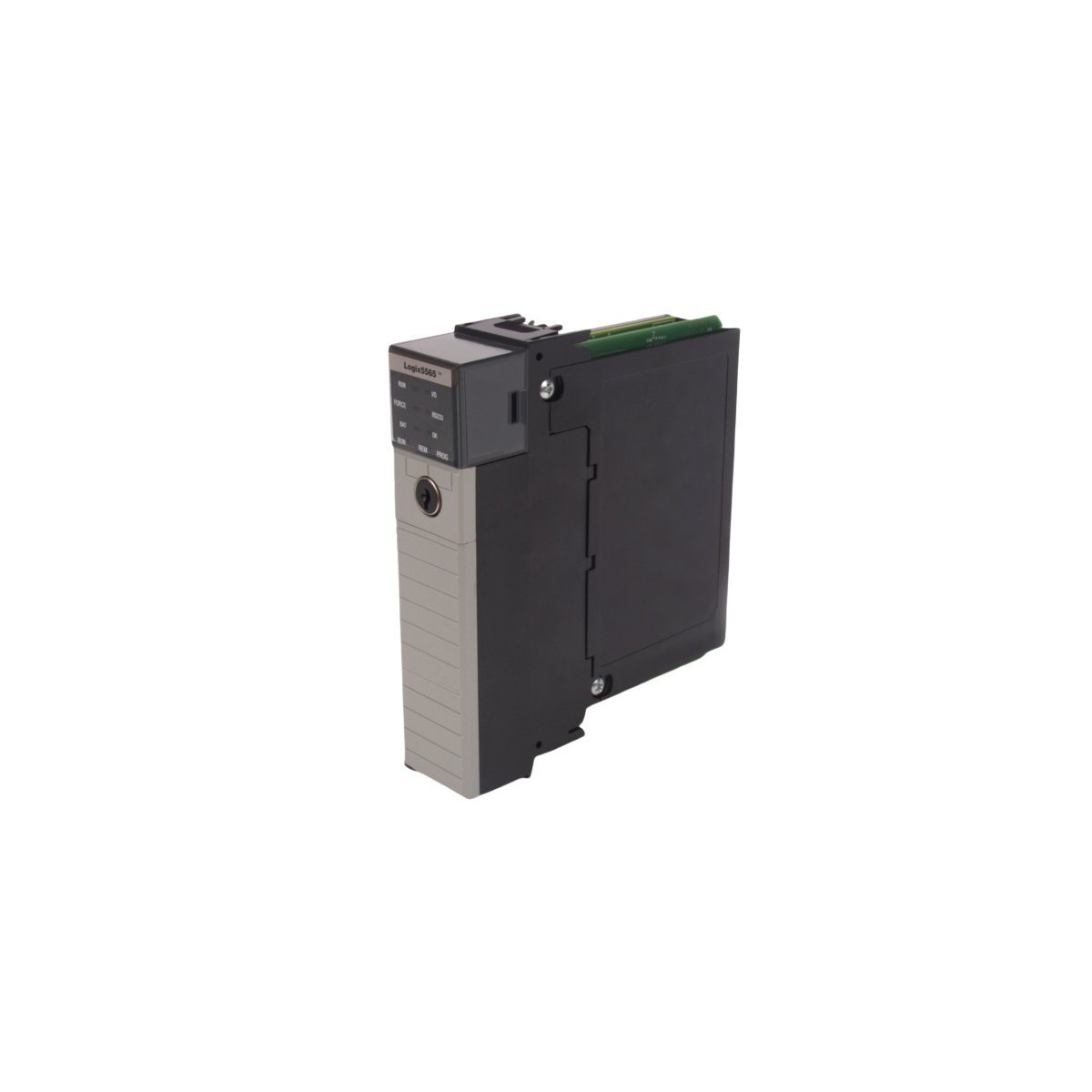
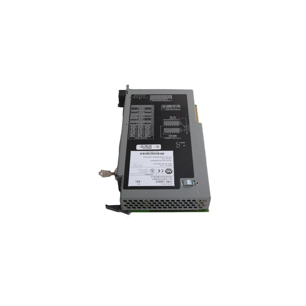
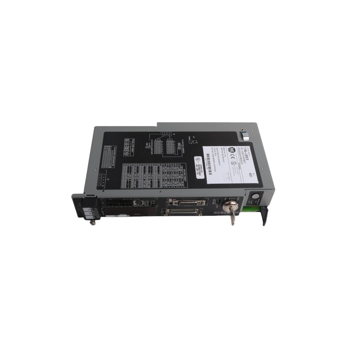
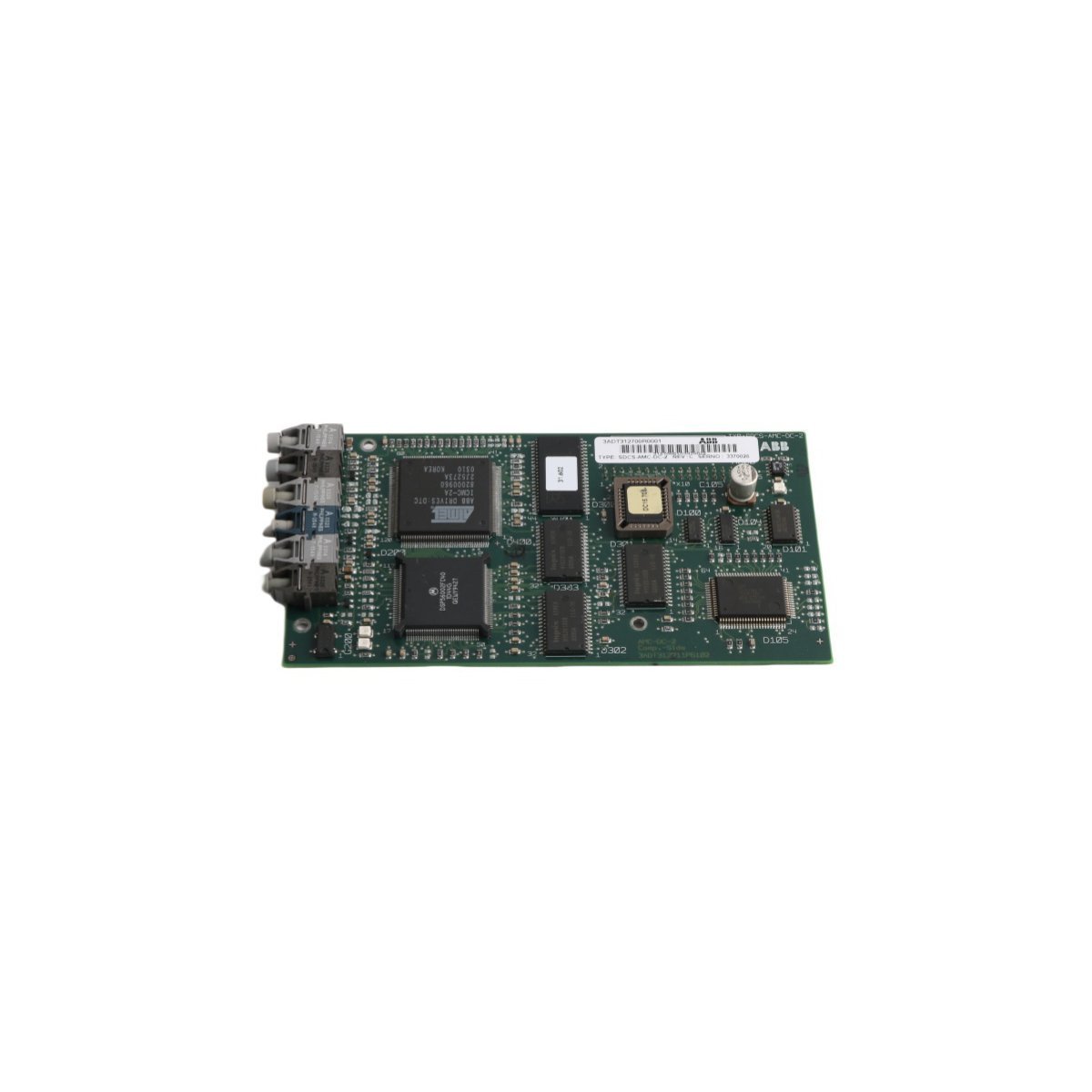
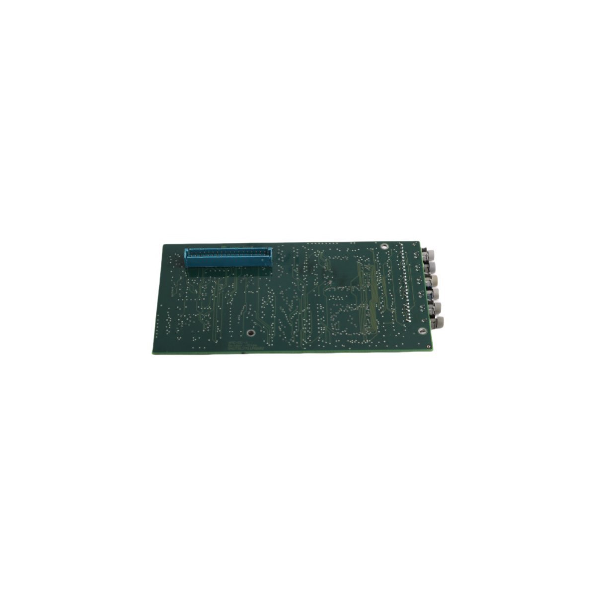
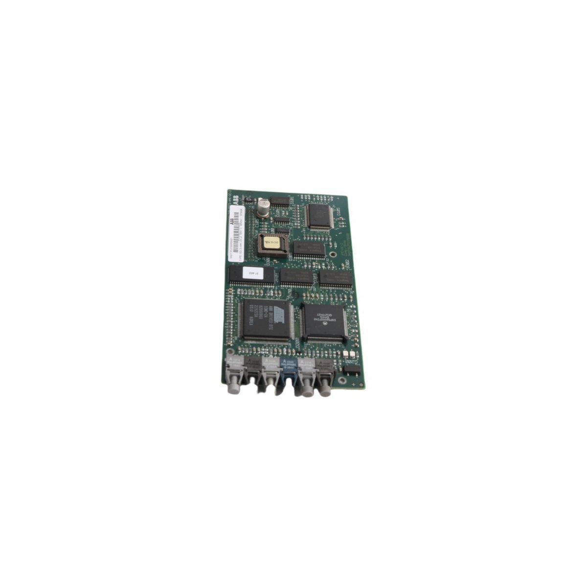
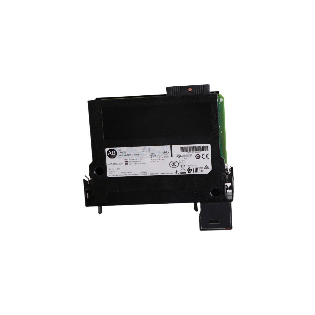
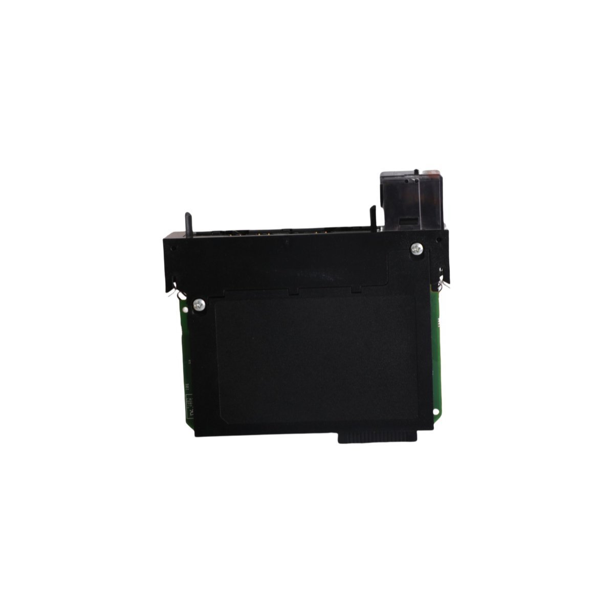
ABB SDCS-AMC-DC-2 3ADT312700R0001 Control Board

Configured for high-speed signal processing and control loop orchestration in DCS 600 drive system architectures, the ABB SDCS-AMC-DC-2 3ADT312700R0001 (SDCS-AMC-DC-2 Control Board) provides direct physical/electrical execution.

Hardware Specifications

ParameterSpecification
ModelSDCS-AMC-DC-2 3ADT312700R0001
BrandABB
OriginSWEDEN
Weight0.08 kg
Dimensions16.3 x 8.3 x 2 cm
Operating TempStandard industrial range
Power ConsumptionStandard system backplane load
Communication ServiceEthernet router
Product RangeDCS 600
Module TypeControl Board
SystemDCS
HS Code8537101190

Deterministic Backplane Execution and Firmware Synchronization

The ABB SDCS-AMC-DC-2 3ADT312700R0001 control board manages internal data flow over dedicated backplane bus communication velocity Licences to ensure low-latency processing during high-speed drive regulation cycles. The board maintains real-time synchronization across connected power stages, leveraging strict firmware flash compatibility protocols to prevent timing drift, instruction mismatches, or signal interruption across expanded industrial drive configurations.

Frequently Asked Questions

Q: What primary function does the SDCS-AMC-DC-2 3ADT312700R0001 serve within the DCS 600 system?

A: It functions as an integrated control board executing real-time system algorithms and routing communication via an embedded Ethernet router interface.

Q: How does the module handle internal system compatibility during startup?

A: Upon initialization, onboard registers verify firmware flash compatibility against host drive parameters to establish deterministic communication paths.

Q: What are the physical dimensions and weight of this control board?

A: The board measures 16.3 x 8.3 x 2 cm and weighs approximately 0.08 kg.

Field Installation Guidelines

  • Verify that all main incoming AC supply power and DC bus link capacitors are fully discharged prior to handling or inserting the control board into the drive assembly.
  • Wear an grounded electrostatic discharge (ESD) wrist strap attached to a verified cabinet ground point to prevent static damage to sensitive surface-mount ICs.
  • Carefully line up board edge connectors with rack guides to avoid bending backplane pins during physical seating.
  • Ensure all retaining screws and grounding standoffs are torqued securely to establish a low-impedance ground path to the chassis frame.