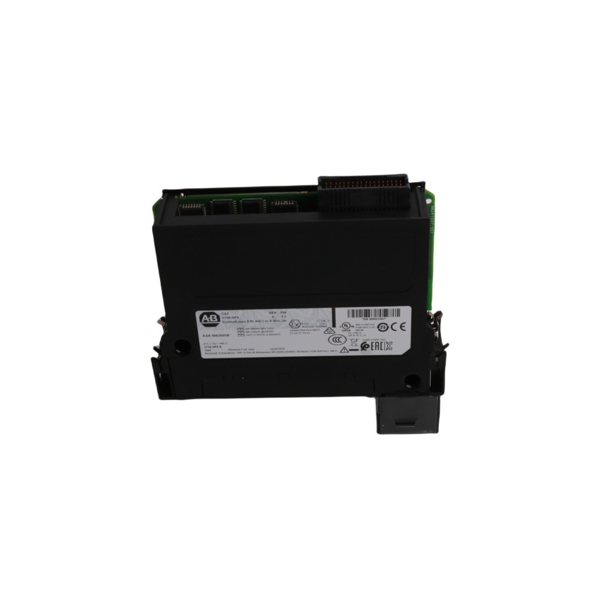
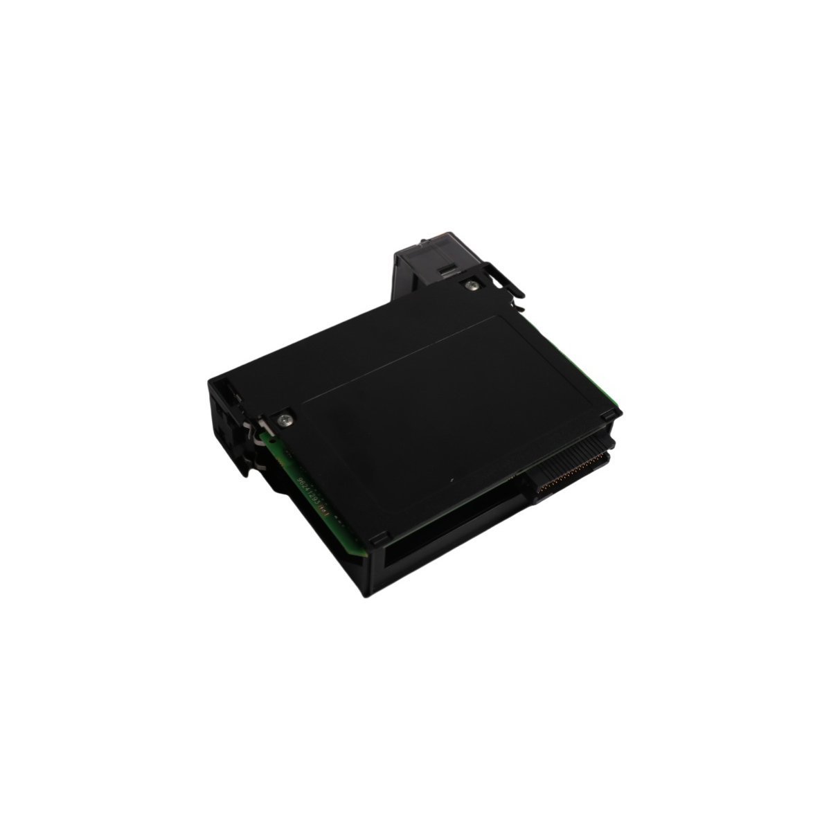
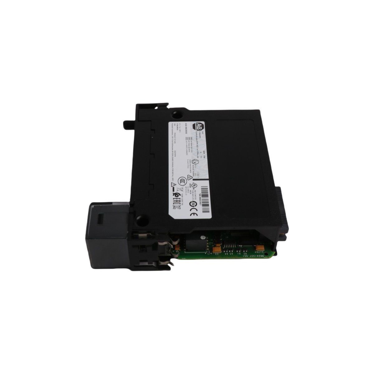
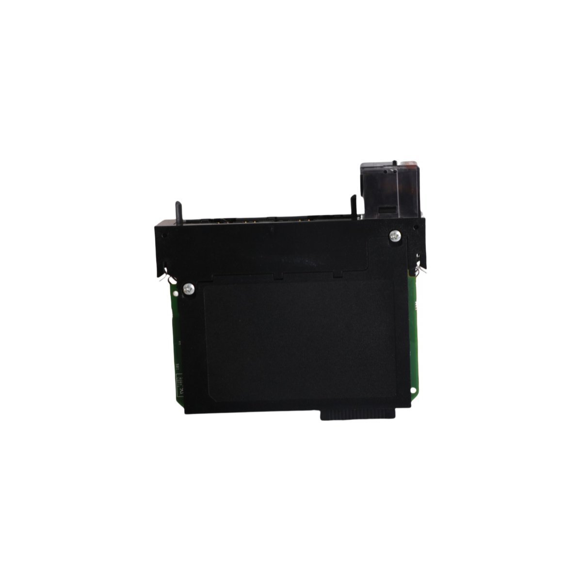
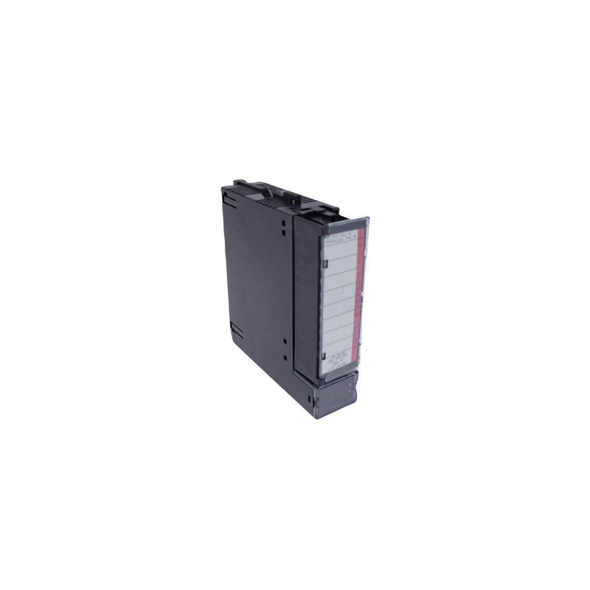
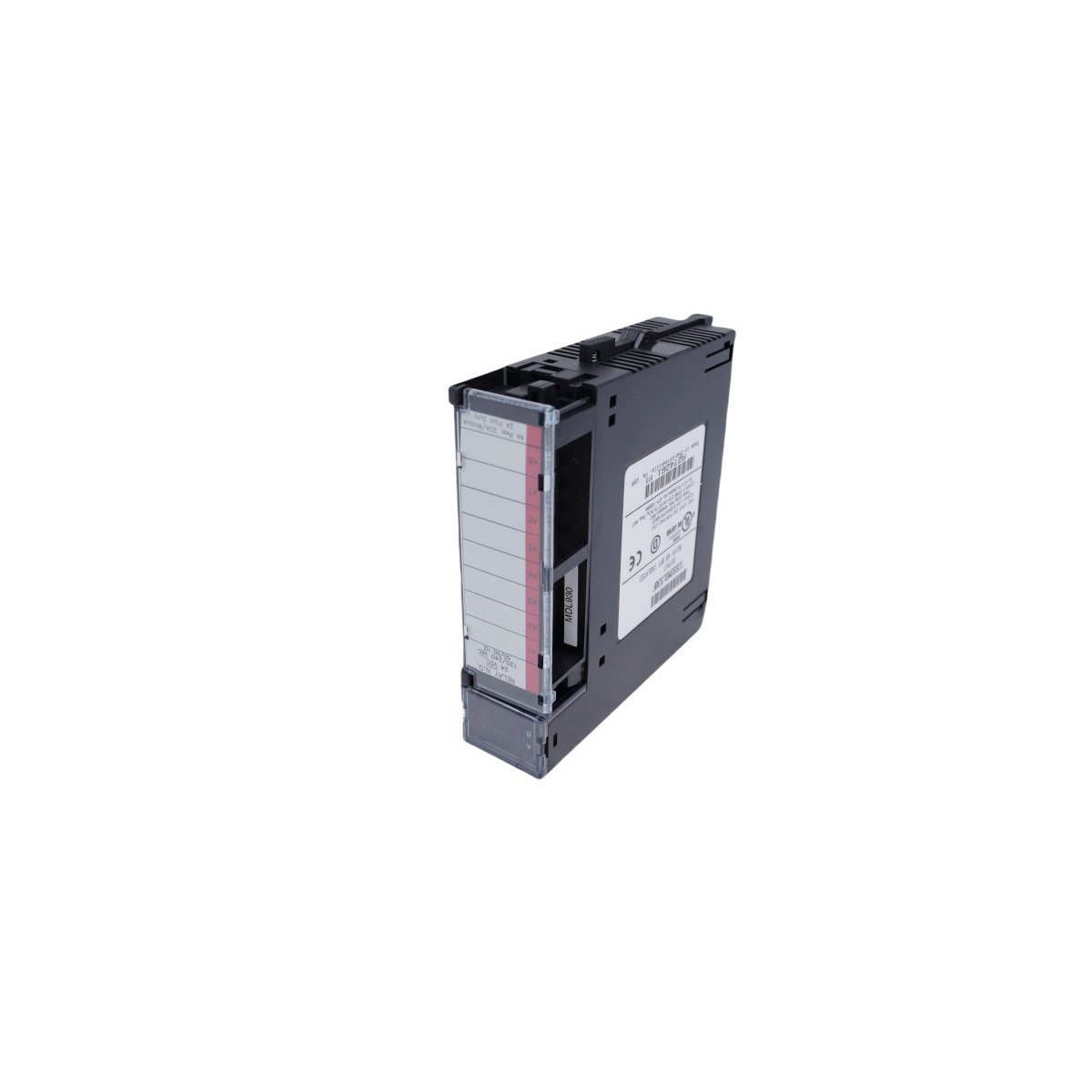
Configured for multi-channel analog signal generation in ControlLogix automation platforms, the Allen Bradley 1756-OF8 (1756-OF8 Analog Output Module) provides direct electrical execution of voltage and current control loops.
Hardware Specifications
Parameter
Specification
Model
1756-OF8
Brand
Allen Bradley
Origin
USA
Weight
0.35 kg
Dimensions
23.3 x 18.3 x 5.3 cm
Operating Temp
Industrial Standard
Power Consumption
System Backplane Dependent
Output Channels
8 Points
Industrial Control and Network Characteristics
The 1756-OF8 module utilizes backplane bus communication velocity to process high-resolution analog output signals within the ControlLogix chassis. Integration into Profinet and EtherNet/IP deterministic networks enables synchronous command execution across distributed I/O racks. Firmware flash compatibility allows for version alignment with current control software, while configurable I/O density scaling supports expansion in modular automation architectures without degrading signal update rates.
Frequently Asked Questions
Q: Does the 1756-OF8 support Removal and Insertion Under Power (RIUP)?
A: Yes, the module supports RIUP within a ControlLogix chassis, provided that the associated field wiring arm is secured correctly and the system is operating within defined environmental limits.
Q: How is the channel isolation configured for this module?
A: The 1756-OF8 utilizes internal galvanic isolation between the backplane and the I/O channels. No external isolation is required for standard loop power configurations, though ground referencing must be verified to prevent common-mode noise.
Field Installation Guidelines
Ensure the ControlLogix chassis power is isolated before initiating module insertion.
Align the module keying to the chassis slot to prevent incorrect installation.
Slide the 1756-OF8 into the chassis until the backplane connector is fully engaged.
Secure the module using the top and bottom latching mechanisms.
Terminate field wiring to the Removable Terminal Block (RTB) according to the specific voltage or current loop wiring diagram (0-10 V or 4-20 mA).
Verify shield termination at the cabinet entry point to suppress electromagnetic interference before energizing the chassis.
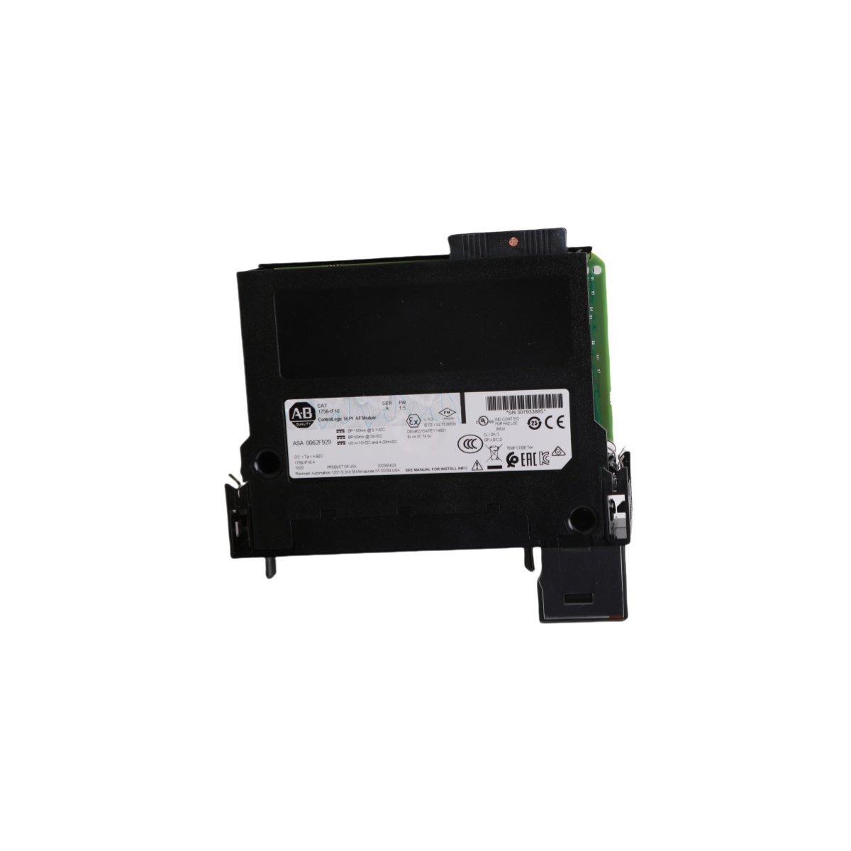
The Allen Bradley 1756-IF16, also cataloged as the 1756-IF16 ControlLogix 16 Pt A/I Module, operates as a dedicated hardware component for analog signal acquisition within industrial programmable logic controller architectures.
Hardware Specifications
Parameter
Specification
Model
1756-IF16
Brand
Allen Bradley
Origin
USA
Weight
0.35 kg
Dimensions
23.3 x 18.2 x 5.3 cm
Operating Temp
0 deg C to 60 deg C
Power Consumption
1 W (backplane current draw at 5.1 VDC: 150 mA)
Profinet / EtherNet/IP Deterministic Networks
The module integrates seamlessly into deterministic industrial network topologies through ControlLogix backplane communication, supporting Producer/Consumer technology to broadcast input data across multiple controllers without polling overhead. Network update intervals are configured via Logix Designer, ensuring synchronous multi-channel sampling schedules across distributed chassis architectures.
Frequently Asked Questions
Q: Does the module support removal and insertion under power (RIUP)?A: Yes, the 1756-IF16 supports RIUP when installed in a standard ControlLogix chassis, allowing hardware replacement without powering down the entire rack system.Q: What is the backplane current consumption profile?A: The module draws 150 mA from the 5.1 VDC backplane rail and 20 mA from the 24 VDC backplane rail during standard operation.Q: How is individual channel filtering configured?A: Digital filter frequencies ranging from 1 Hz to 60 Hz can be independently assigned to each of the 16 channels via software configuration to attenuate industrial line noise.
Field Installation Guidelines
Mount the module into any available slot within a standard ControlLogix chassis using the chassis guide rails, ensuring the latching mechanism engages securely. Connect shielded twisted-pair cables to the removable terminal block (RTB) to mitigate electromagnetic interference. Terminate cable shields to the nearest functional earth ground bar using grounding lugs. Verify backplane power status prior to seating the module to prevent electrical transients.
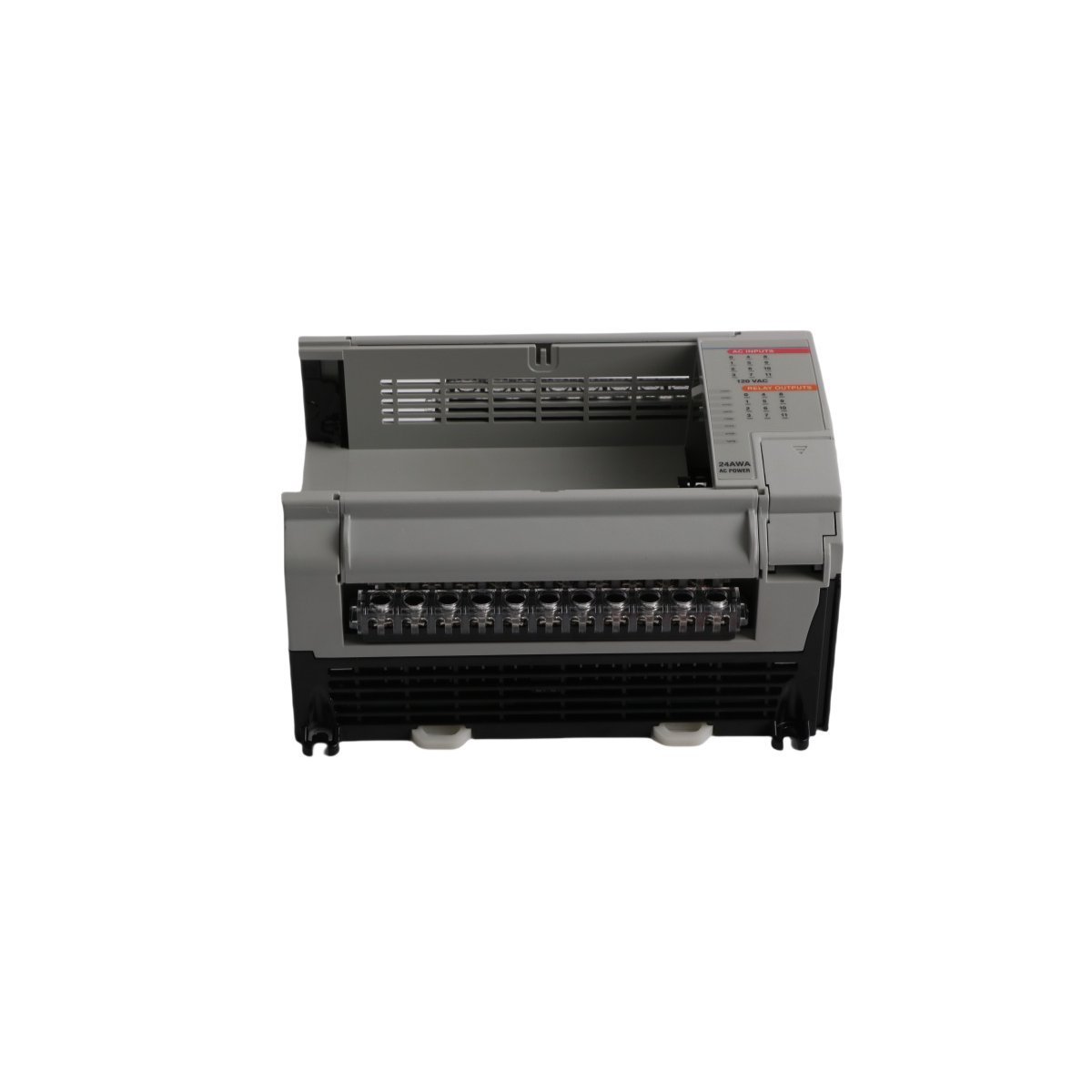
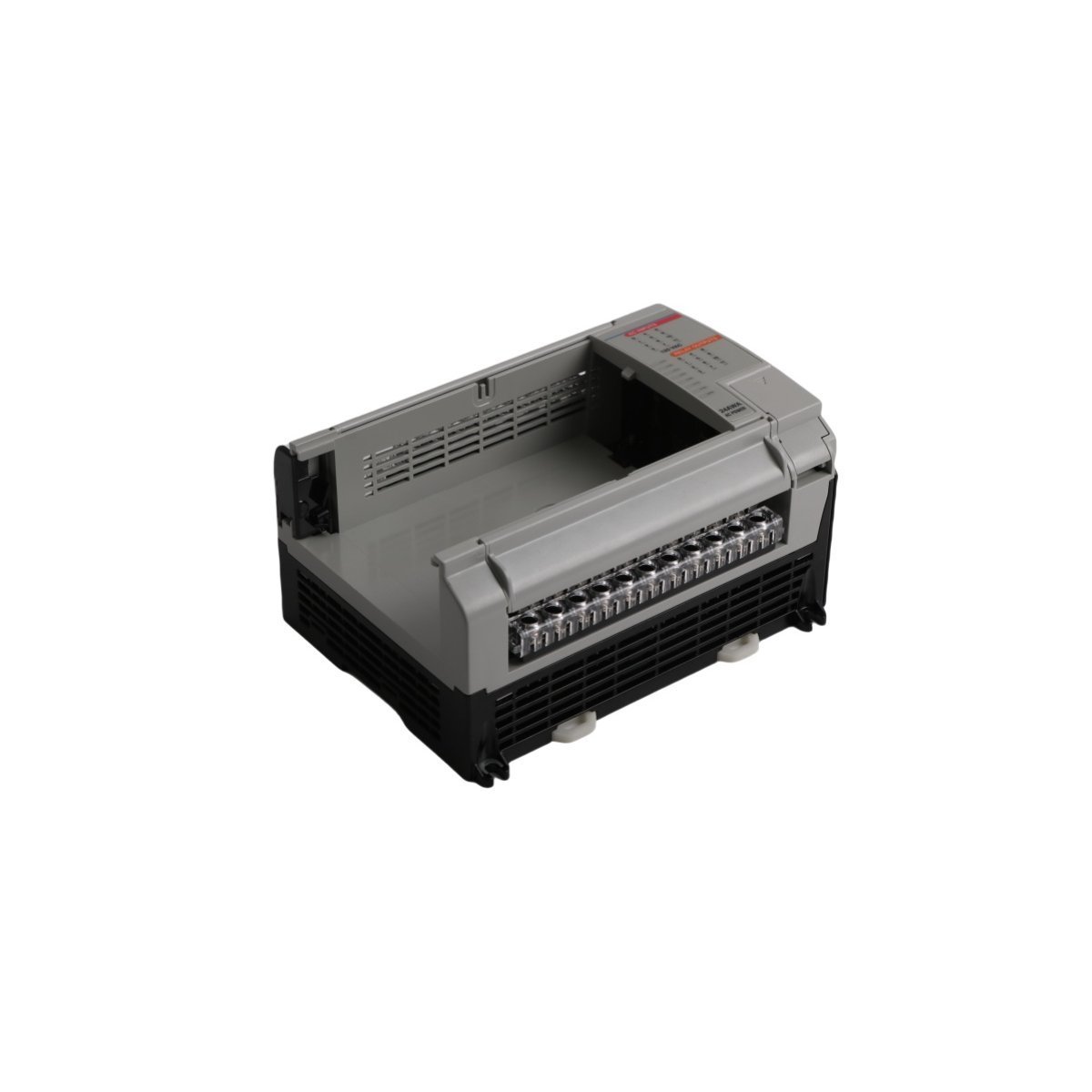
The Allen-Bradley 1764-24AWA is a 120 VAC powered MicroLogix 1500 PLC base unit featuring 12 embedded AC inputs and 12 relay outputs. Brand new factory-sealed units are ready for industrial machinery deployments with fast worldwide shipping. Keep your legacy control panels running efficiently.
The Emerson KJ3001X1-BG1 is a DeltaV SIS safety output module. It features 12P0557X162/VE4002S1T1B2 hardware for SIL-rated industrial safety and emergency shutdown control.
The Yokogawa ADR541-P10 S1 is a 16-channel analog output module designed for the CENTUM VP DCS. It features PWM and time-proportional control, providing precise signal management for field devices in demanding industrial automation environments.
The Allen-Bradley 1794-OE12 is a 12-channel FLEX I/O analog output module. It offers 16-bit resolution for ±10V and 4-20mA signals with 0.1% accuracy. This high-density module provides precise control for actuators and process valves in distributed I/O systems.
The Allen-Bradley 1756-OF6VI is a 6-channel isolated analog voltage output module for ControlLogix systems. It features 13-bit resolution and 250V channel-to-channel isolation. This module provides precise ±10V control for actuators and drives in demanding industrial environments.
The Allen-Bradley 1746-NO4I is a 4-channel analog current output module for SLC 500 controllers. It provides 16-bit resolution for 0-20mA and 4-20mA signals. This compact 0.2kg module ensures precise control for valves and drives in industrial automation.
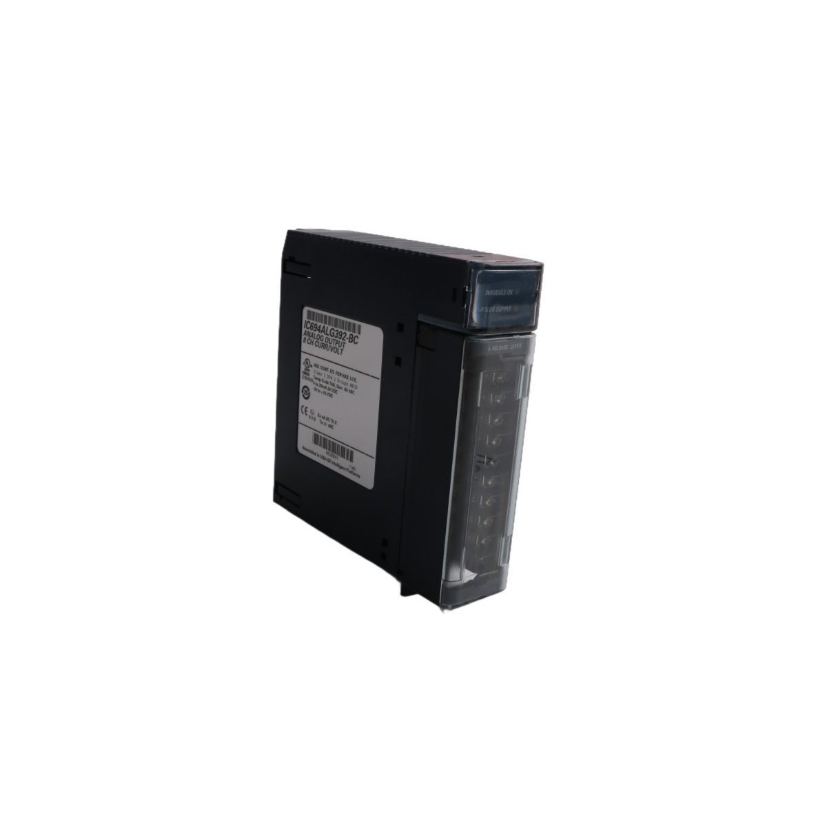
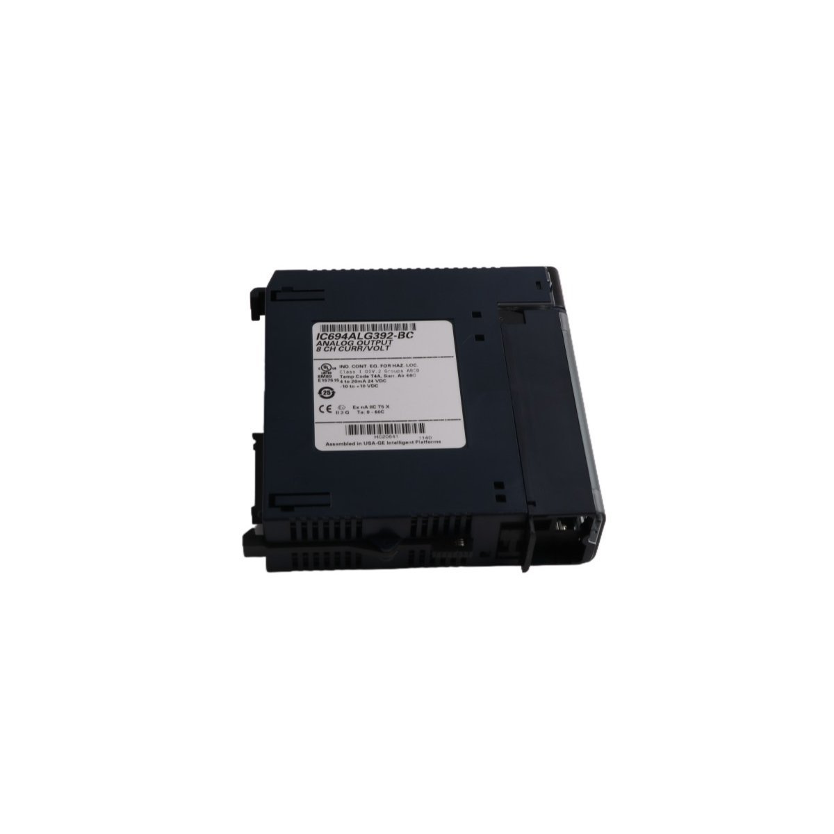
The GE Emerson IC694ALG392 is a high-density PACSystems RX3i analog output module featuring 8 independent channels. It supports voltage and current signals (±10V, 4-20mA) with 16-bit resolution, providing precise control for valves and VFDs in demanding industrial automation applications.
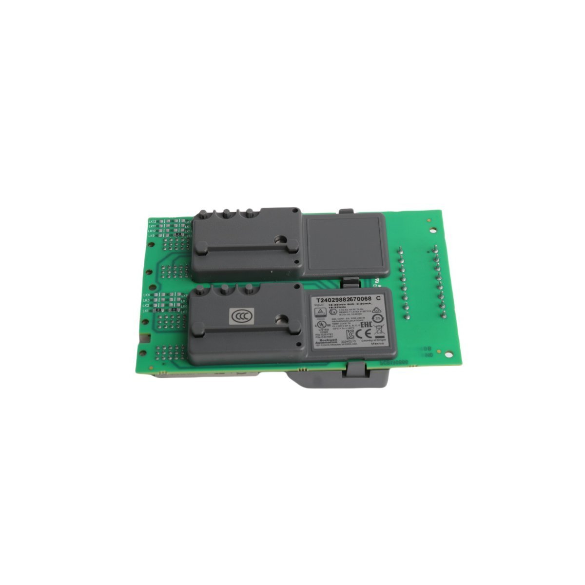
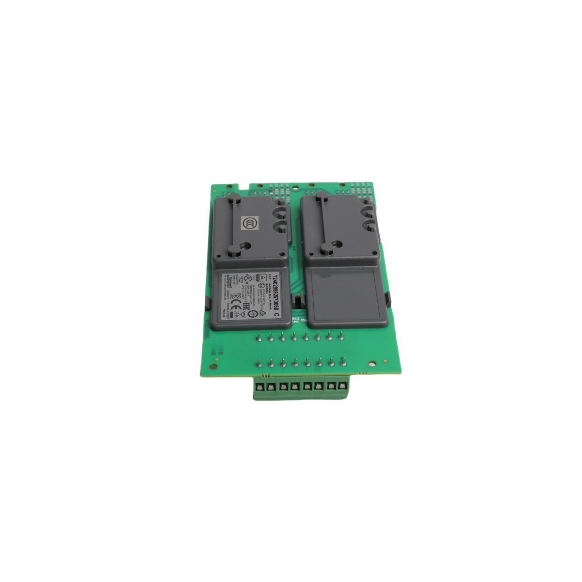
The ICS Triplex T9882 is a high-integrity Analog Output Module designed for the Regent Control System. Featuring a Triple Modular Redundant (TMR) architecture, this 0.55 kg module provides precise control for actuators and valves in safety-critical environments. Its rugged USA-made design and real-time diagnostics ensure maximum uptime and accuracy for oil, gas, and power generation industries.
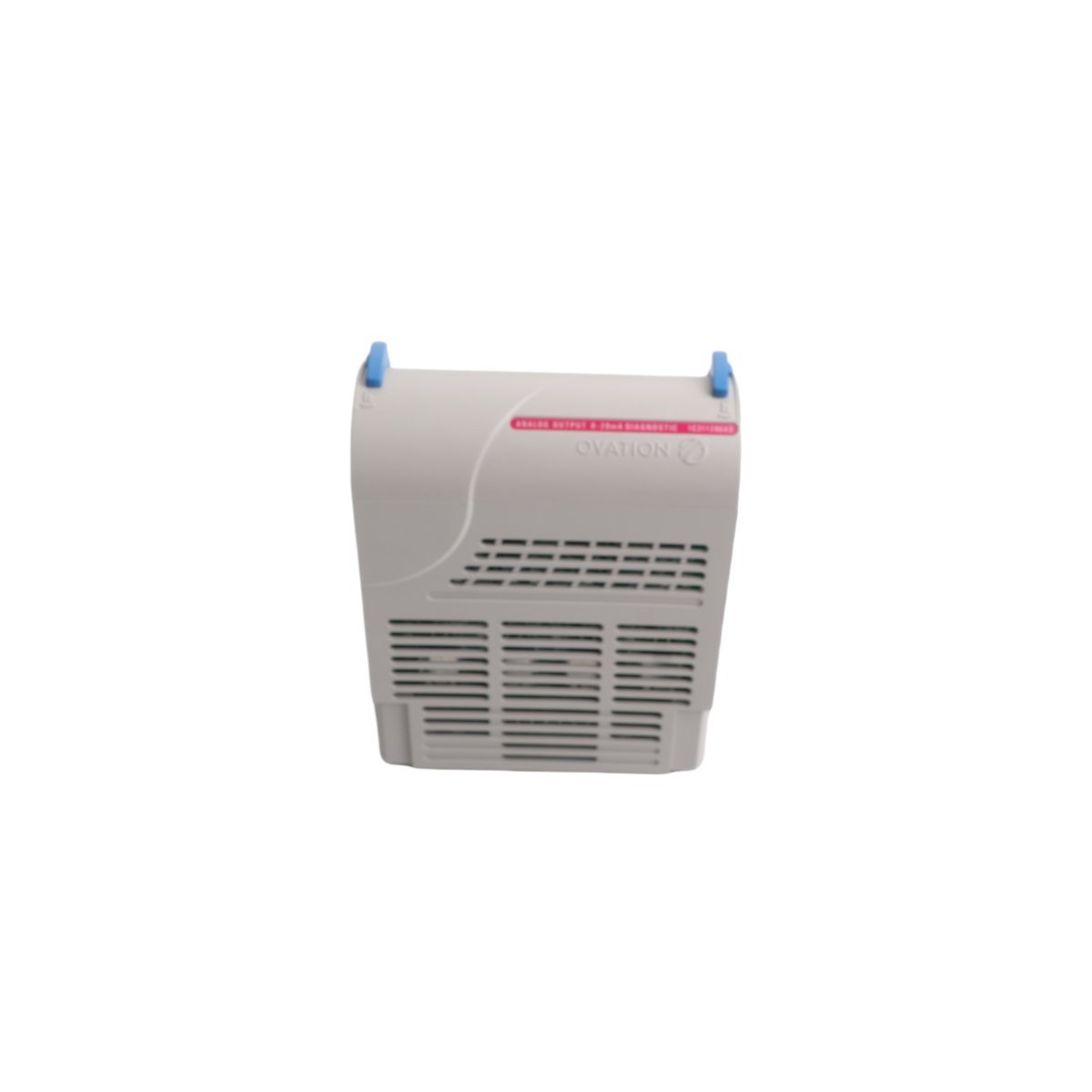
The Emerson 1C31129G03 is a precision Ovation Analog Output module designed for high-accuracy control of field actuators and valves. Featuring isolated signal paths and advanced loop diagnostics, this 4-20 mA module ensures stable and reliable process regulation within complex Distributed Control System architectures.
The Allen-Bradley 1769-OF4 is a 4-channel analog output module for CompactLogix and MicroLogix 1500 systems.Equipped with 15-bit resolution and support for both voltage and current signals, it provides precise control for VFDs and actuators in industrial environments.
The GE Fanuc IC693MDL930 is an 8-point isolated relay output module for Series 90-30 and RX3i PLCs. It provides eight independent N.O. contacts rated at 4A each, supporting both AC and DC field voltages. This module is engineered for high-current switching of motor starters and solenoids with superior channel-to-channel isolation.
We are committed to protecting your privacy. The information collected here is strictly used to provide the requested quotes, technical support, and relevant industrial automation solutions.