Sale!
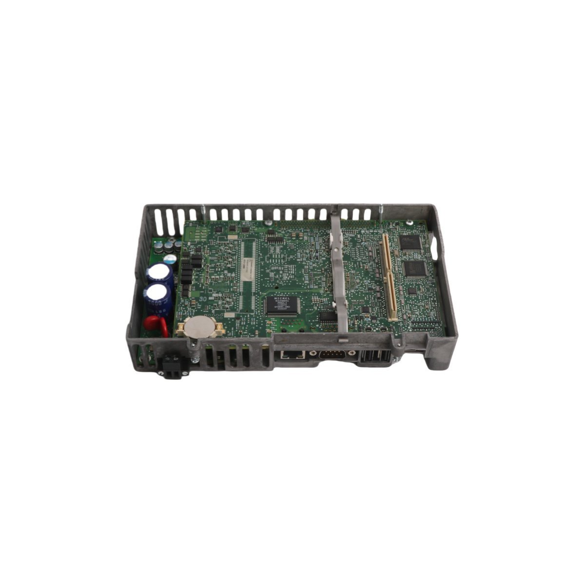
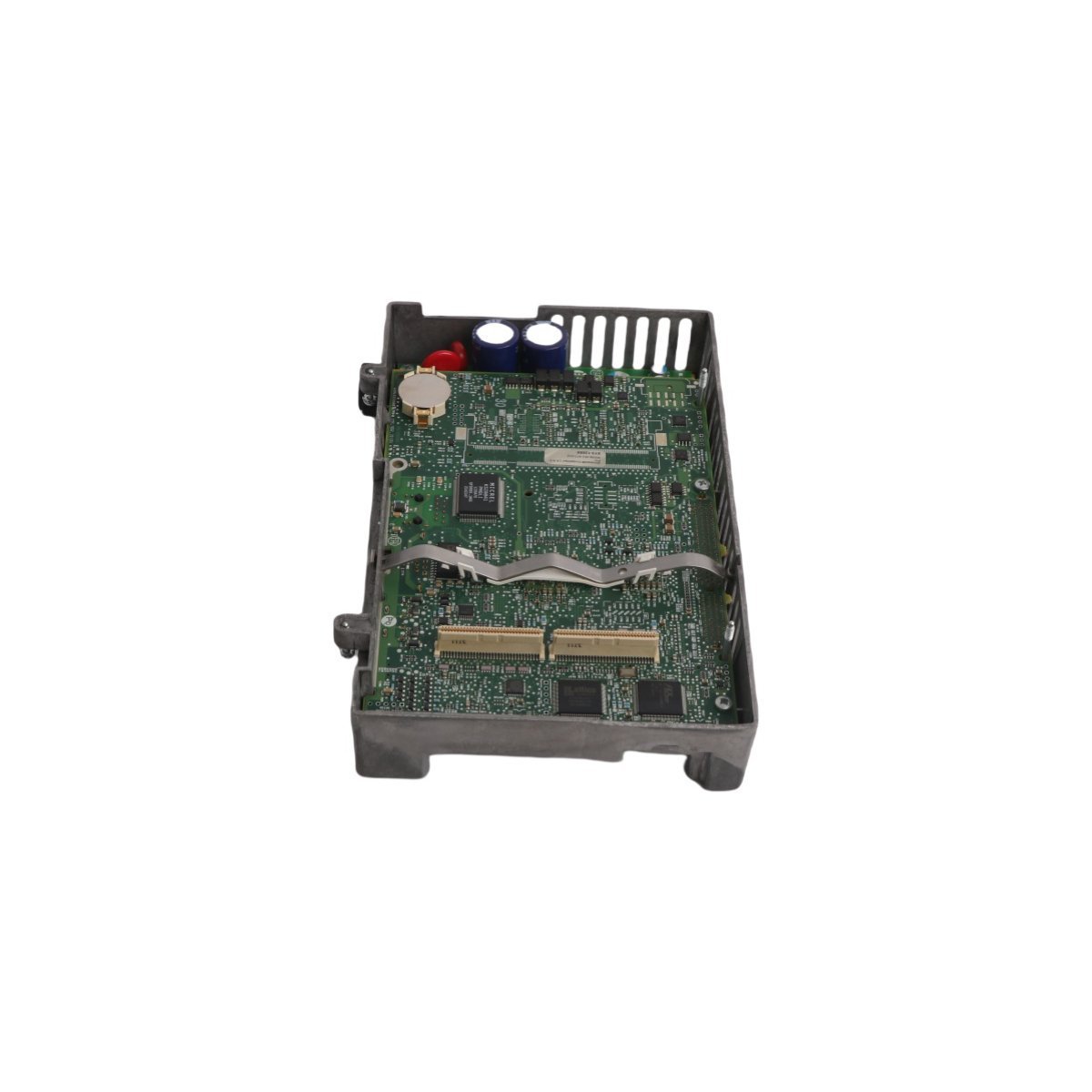
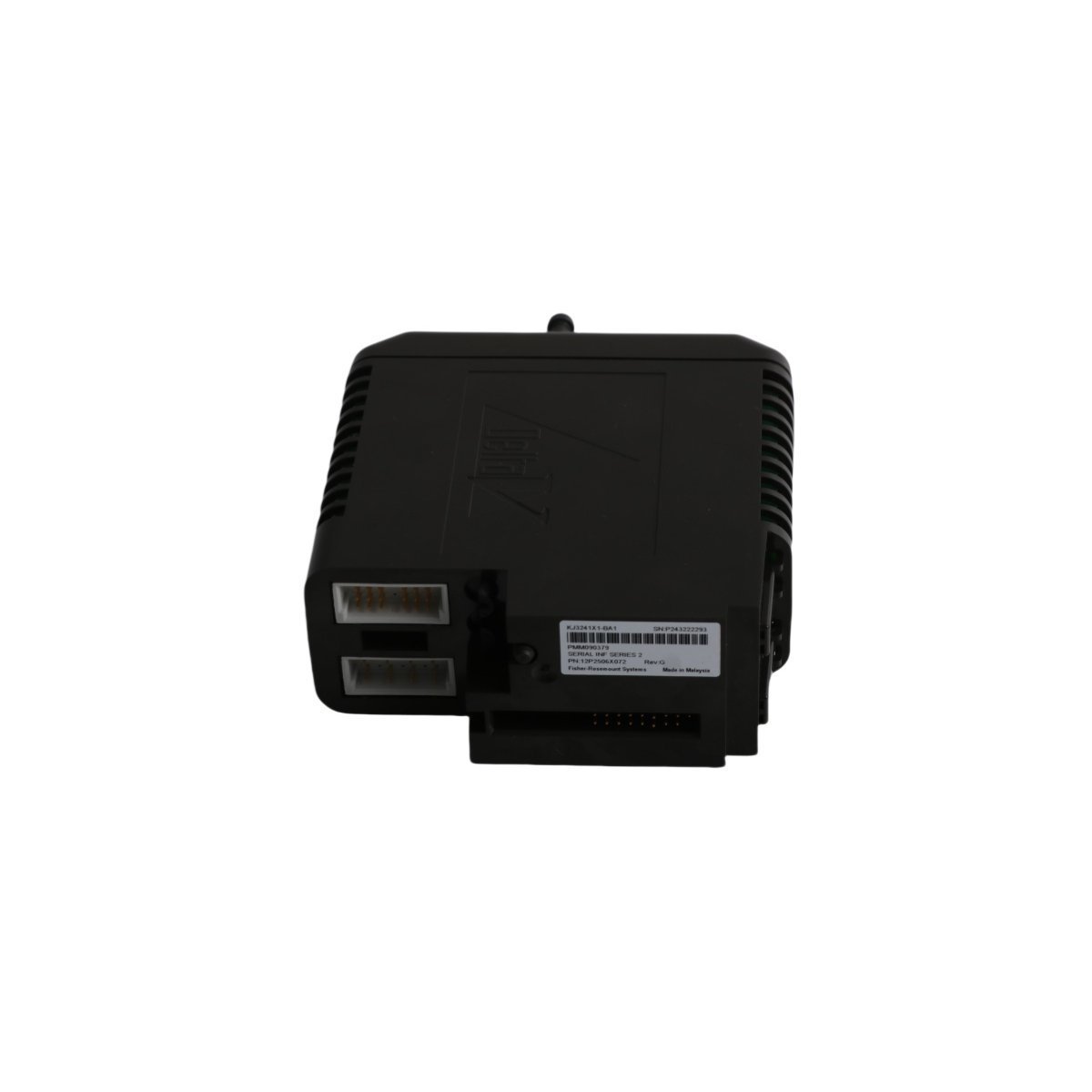
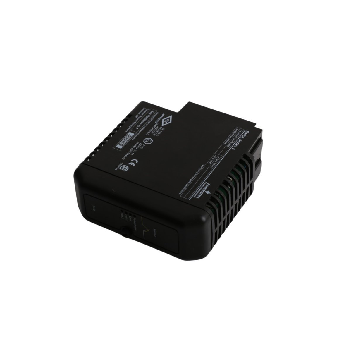
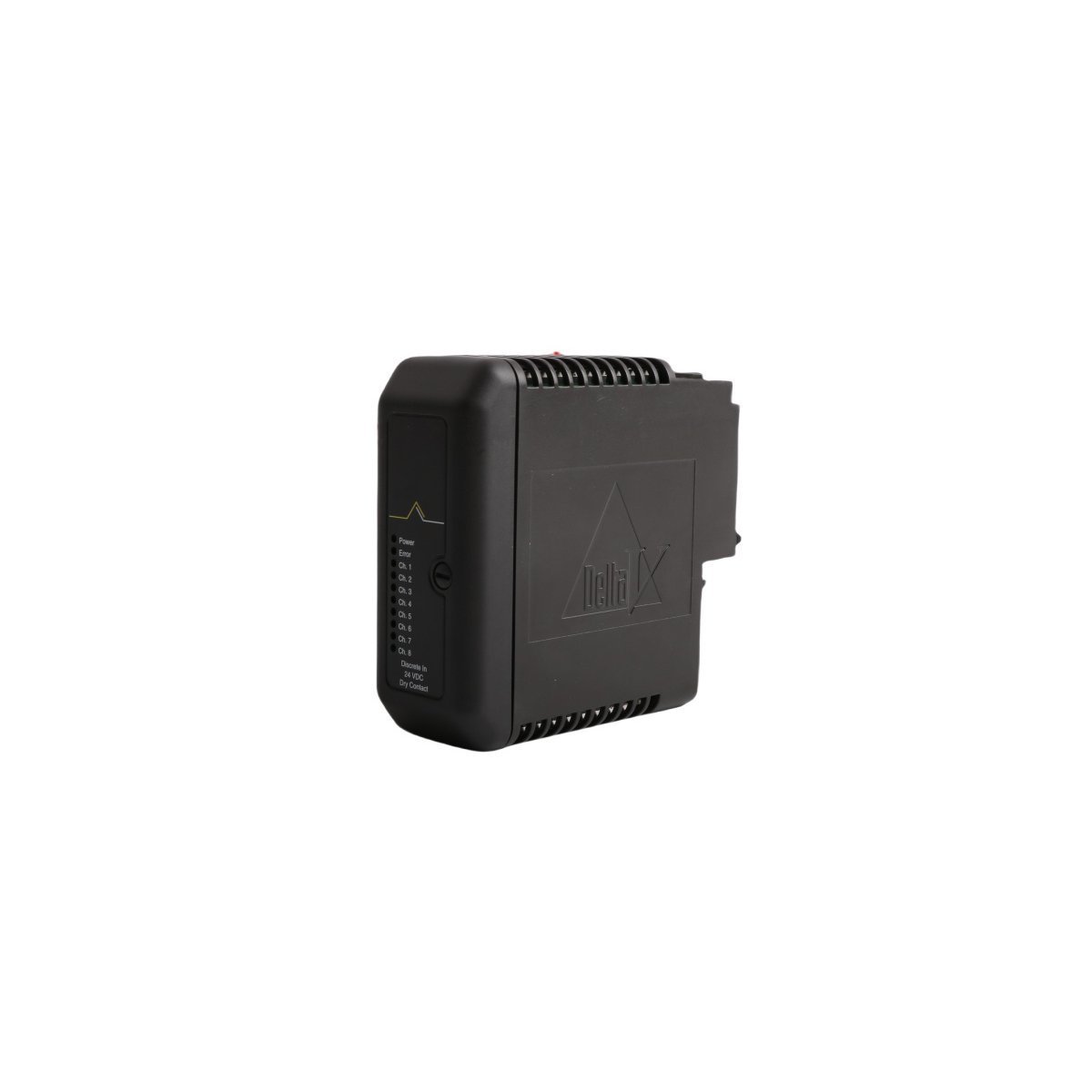
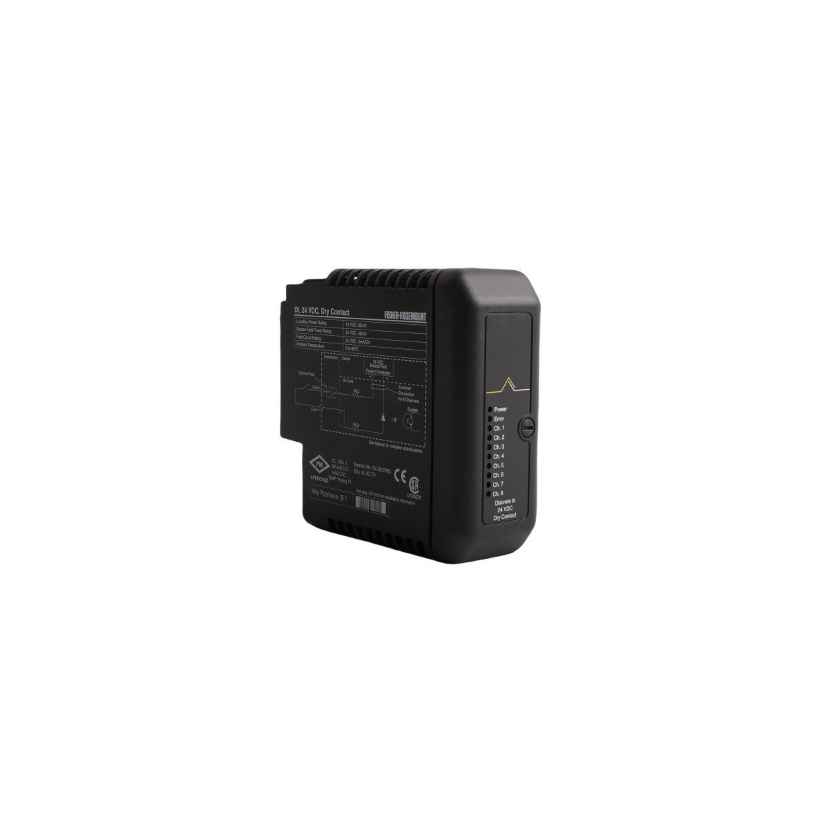
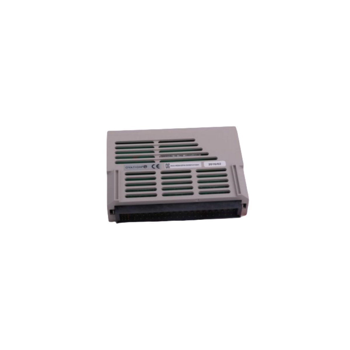
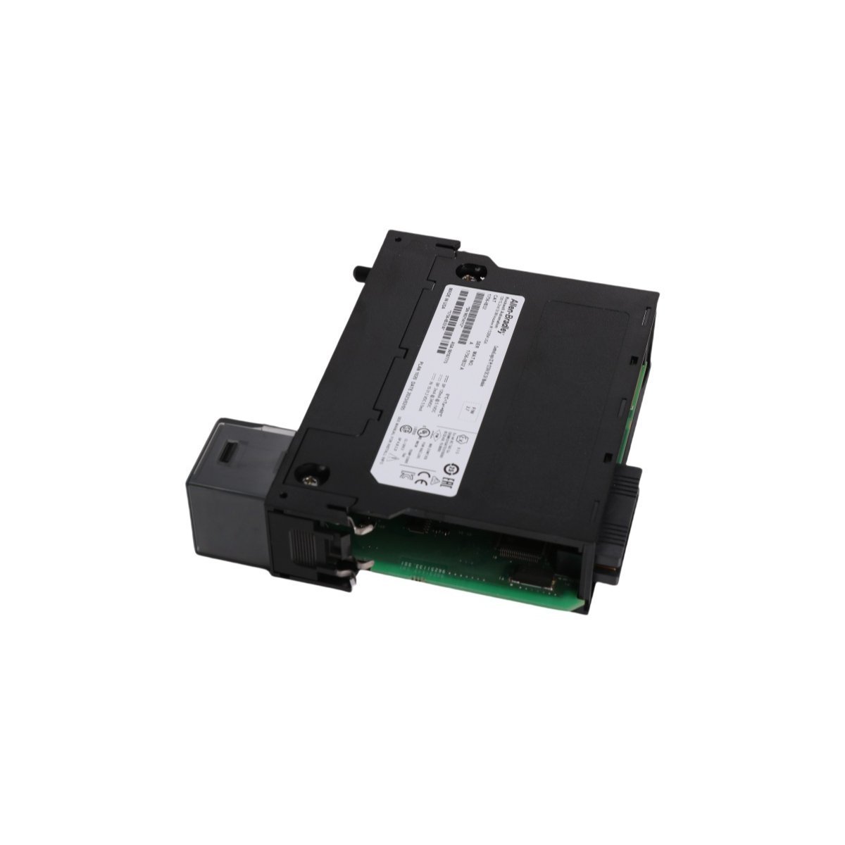
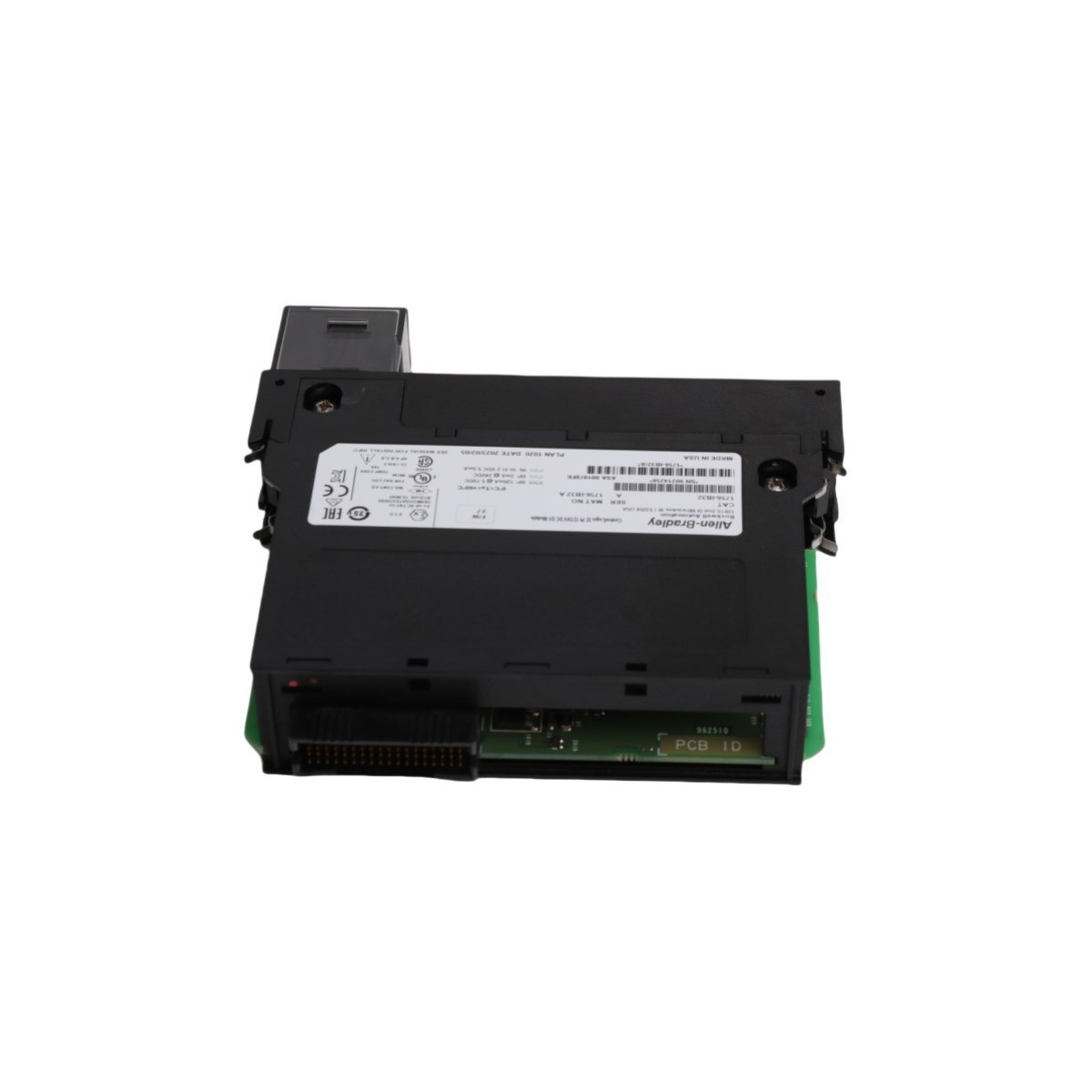
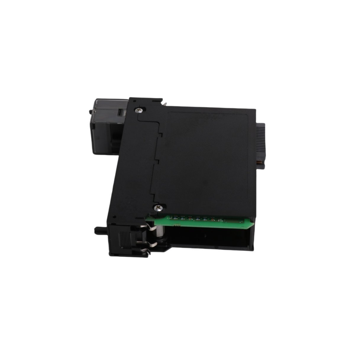
Allen Bradley 2711P-RP1X PanelView Plus Logic Module
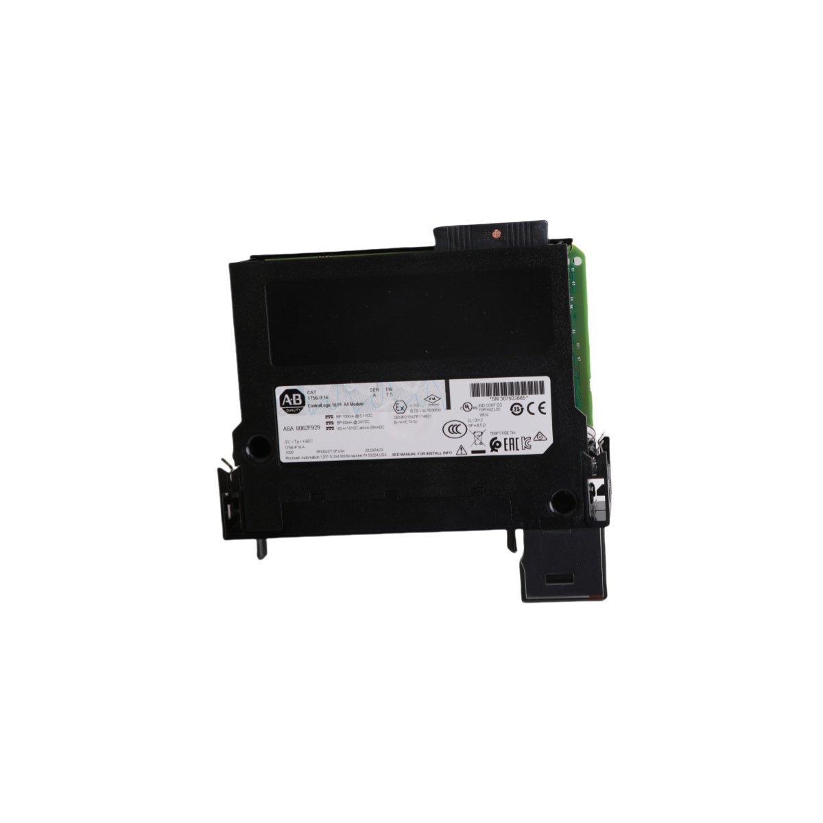
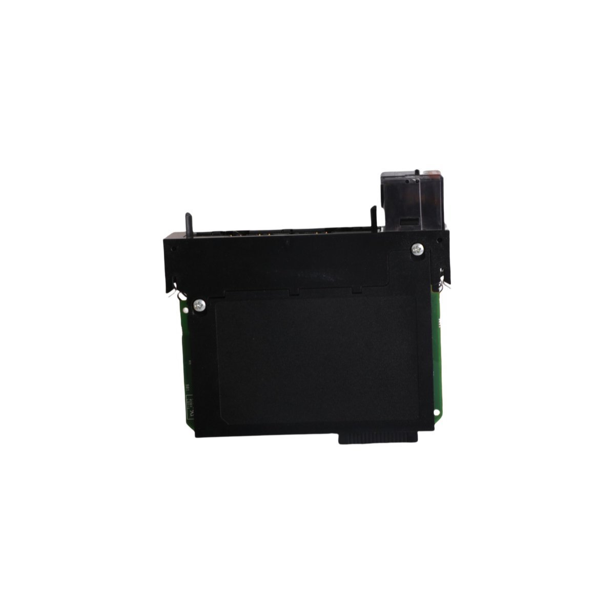
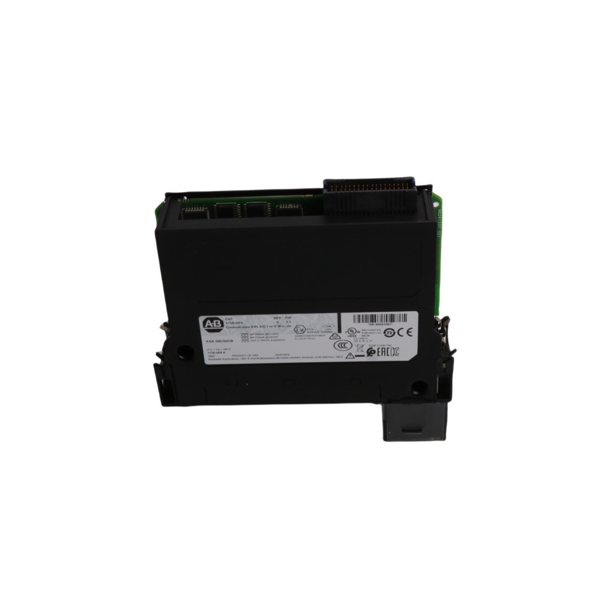
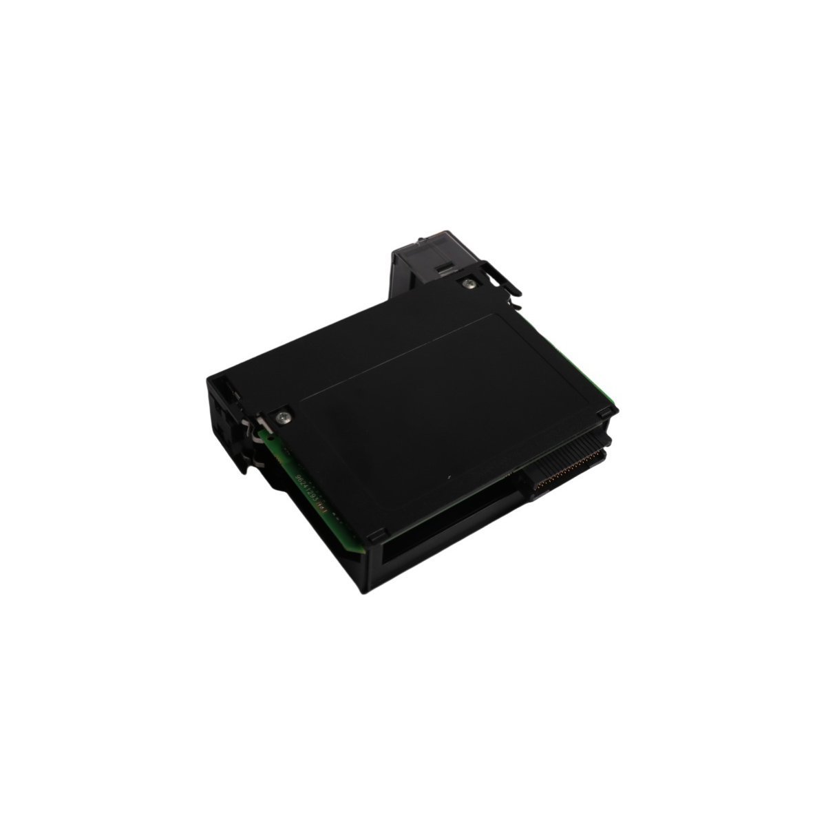
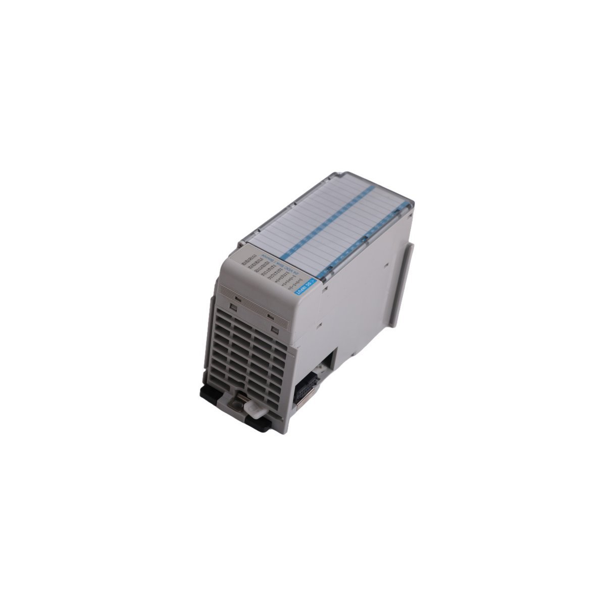
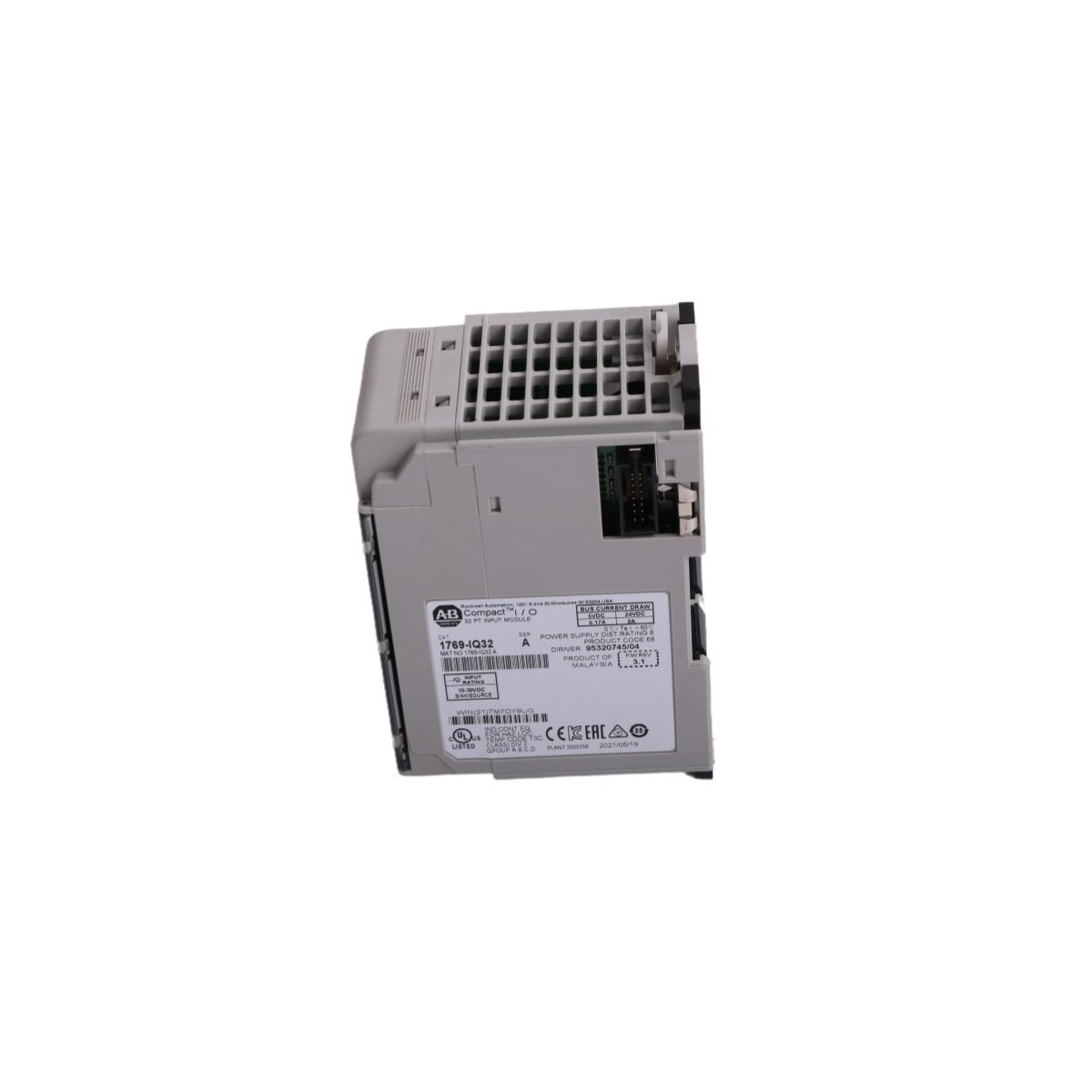
The Allen Bradley 2711P-RP1X, also cataloged as the 2711P-RP1 Logic Module, operates as a dedicated hardware component for graphical execution and display processing within PanelView Plus terminal architectures.
Hardware Specifications
| Parameter | Specification |
|---|---|
| Model | 2711P-RP1X |
| Brand | Allen Bradley |
| Origin | USA |
| Weight | 0.66 kg |
| Dimensions | 20.8 x 14.0 x 4.5 cm |
| Operating Temp | 0 to 55 deg C |
| Power Consumption | 15 W max |
| System Type | PanelView Plus HMI System |
| OS Environment | Windows CE .NET |
| HS Code | 8537101190 |
EtherNet/IP Deterministic Networks & Backplane Scaling
The module executes real-time protocol processing for deterministic EtherNet/IP communications across backplane architectures. Dedicated onboard memory registers handle high-density I/O polling and tag synchronization directly from ControlLogix processors without CPU cycle starvation. High-speed bus arbitration ensures minimal latency during real-time data frame transfers between external PLC controllers and internal application runtime instances.Frequently Asked Questions
Q: Can the 2711P-RP1X logic module be attached to any PanelView Plus display module size?A: The module mechanically attaches to PanelView Plus display modules ranging from 700 to 1500 series configurations using standard retention screws.Q: How is thermal dissipation handled during continuous panel enclosure mounting?A: Heat dissipation occurs passively via the rear enclosure heat sink ribs; maintaining 50 mm clearance around all ventilation slots prevents internal thermal throttling.Field Installation Guidelines
- Disconnect all primary DC power inputs from the terminal base prior to mating or unseating the logic module from the display housing.
- Torque all rear structural locking screws to 1.1 Nm (10 in-lb) to maintain uniform contact force across internal board-to-board connectors.
- Route network communication cables through dedicated wire raceways separated from 120/230 VAC power feeds by at least 200 mm.
- Verify proper panel ground bond resistance of less than 1 ohm between the module chassis ground terminal and the main enclosure earth bus.