Sale!
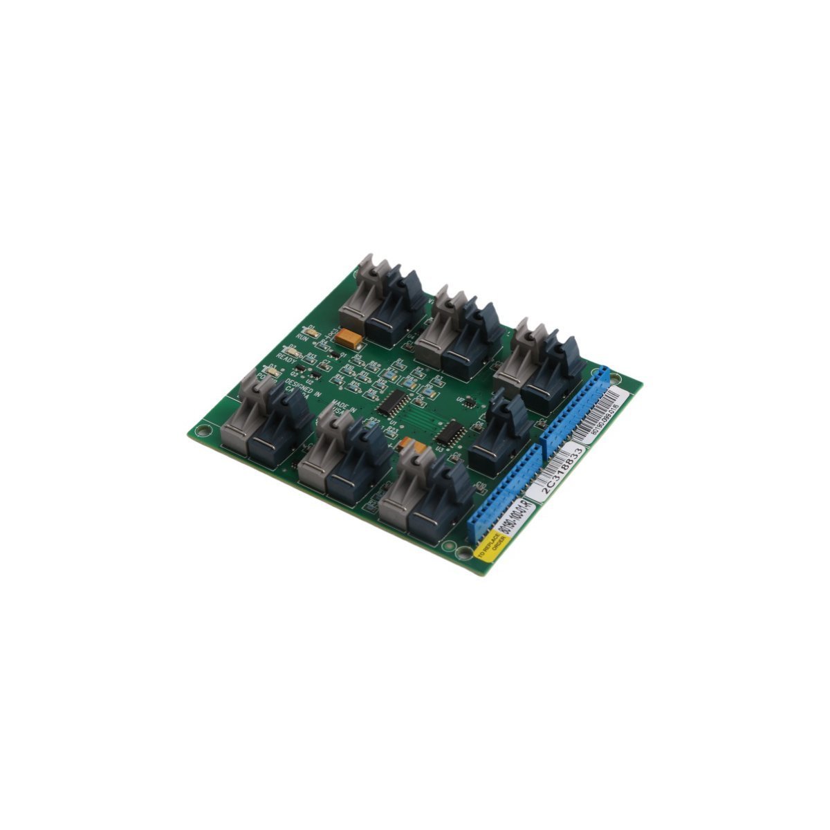
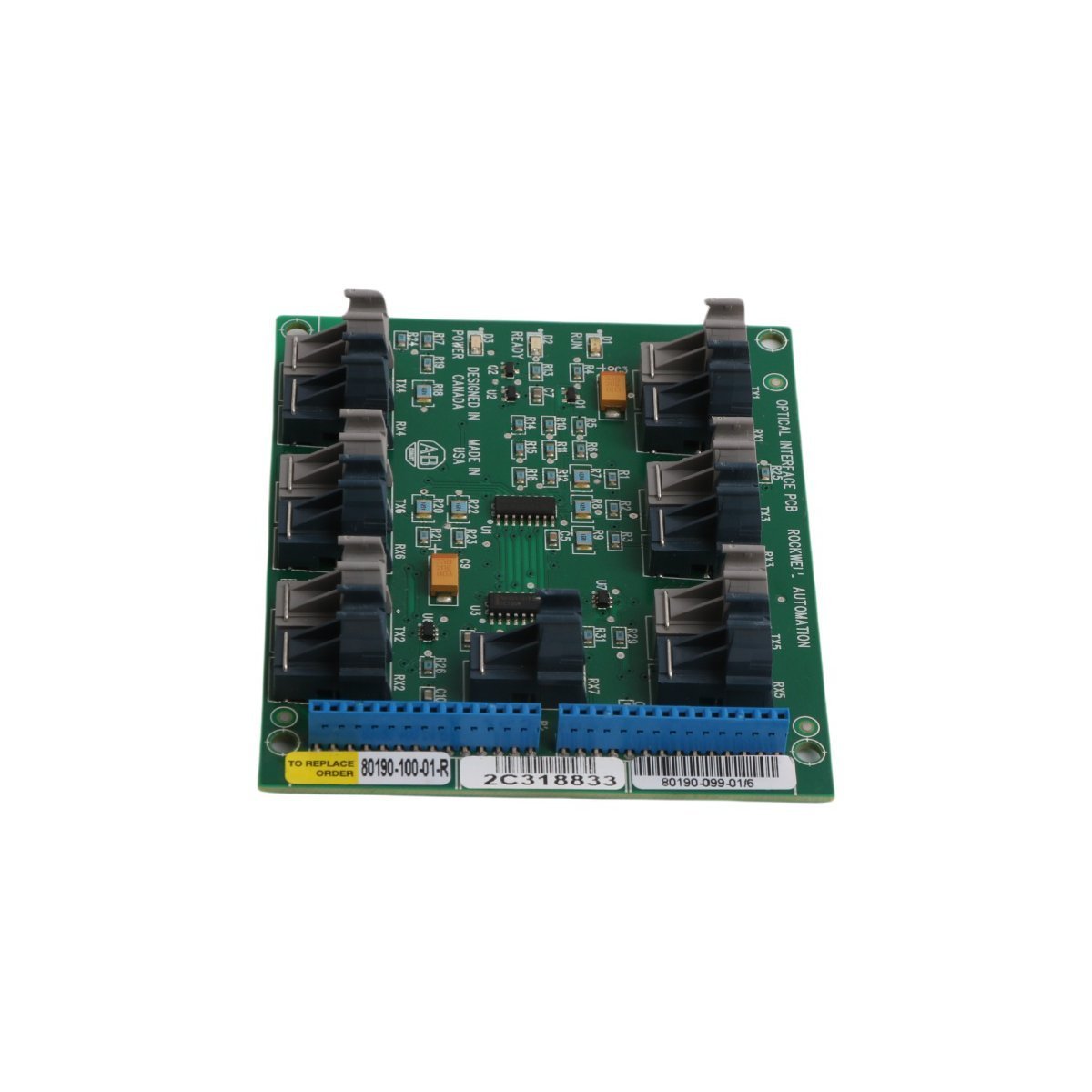
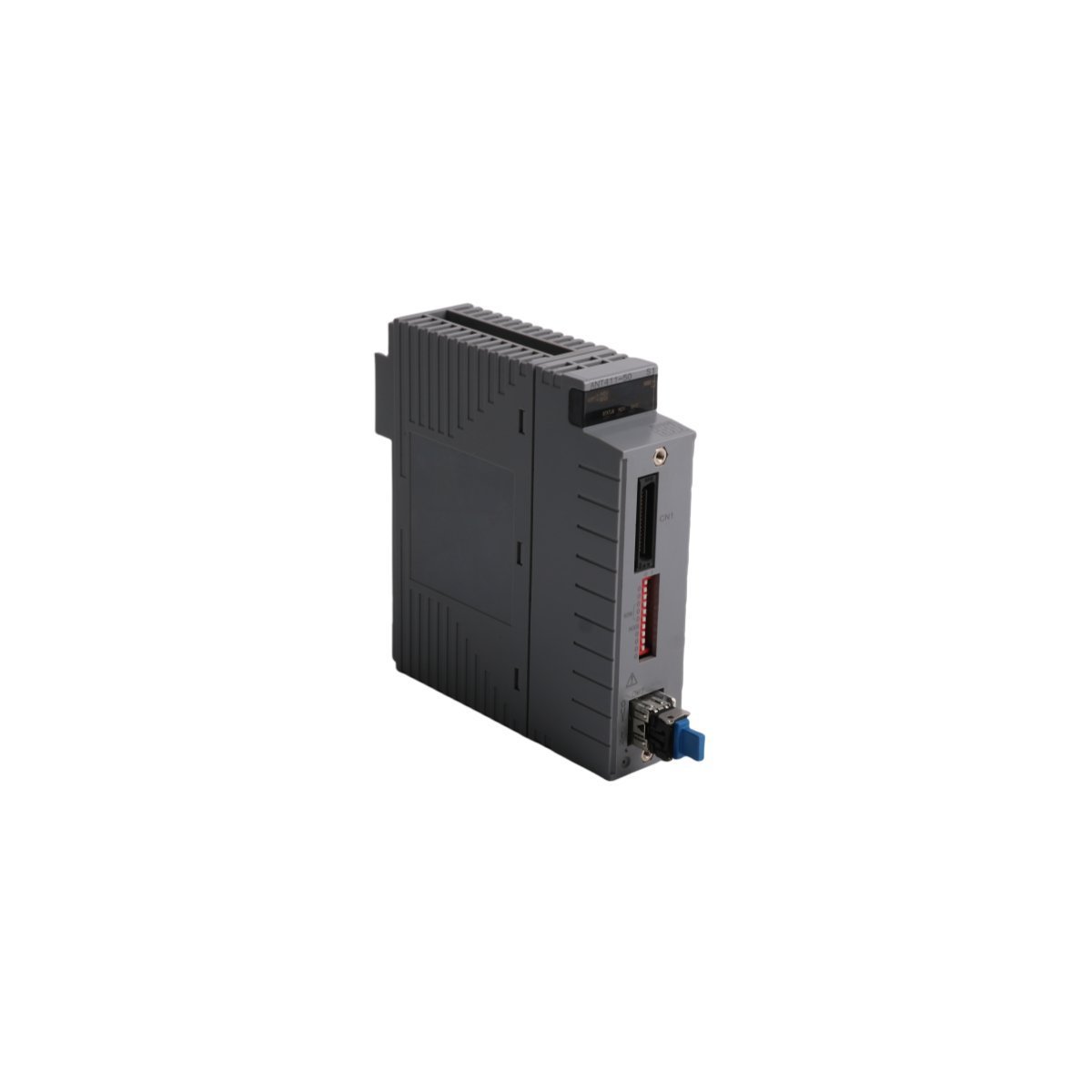
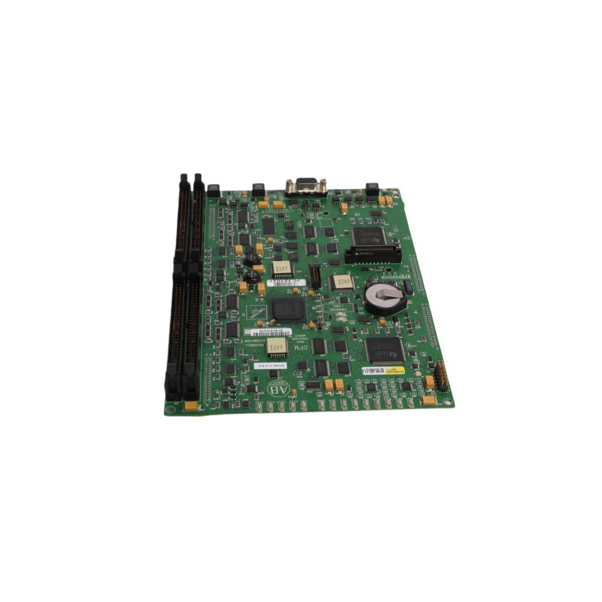
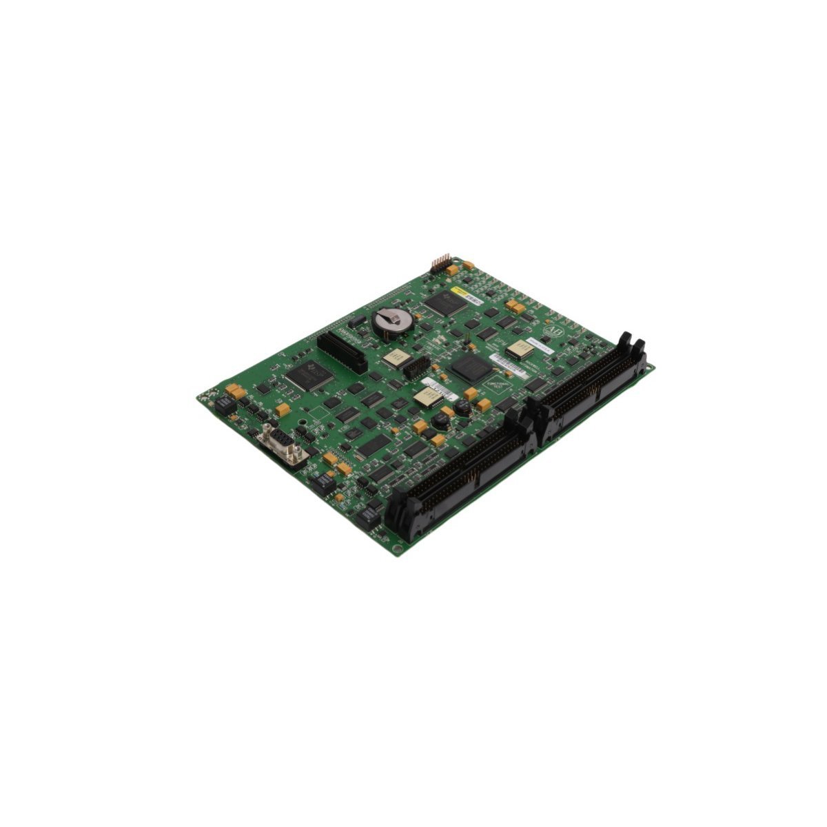
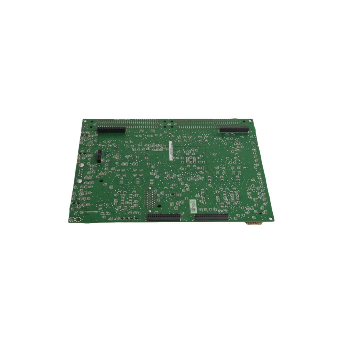
Allen Bradley 80190-100-01-R Fiber Optic Board
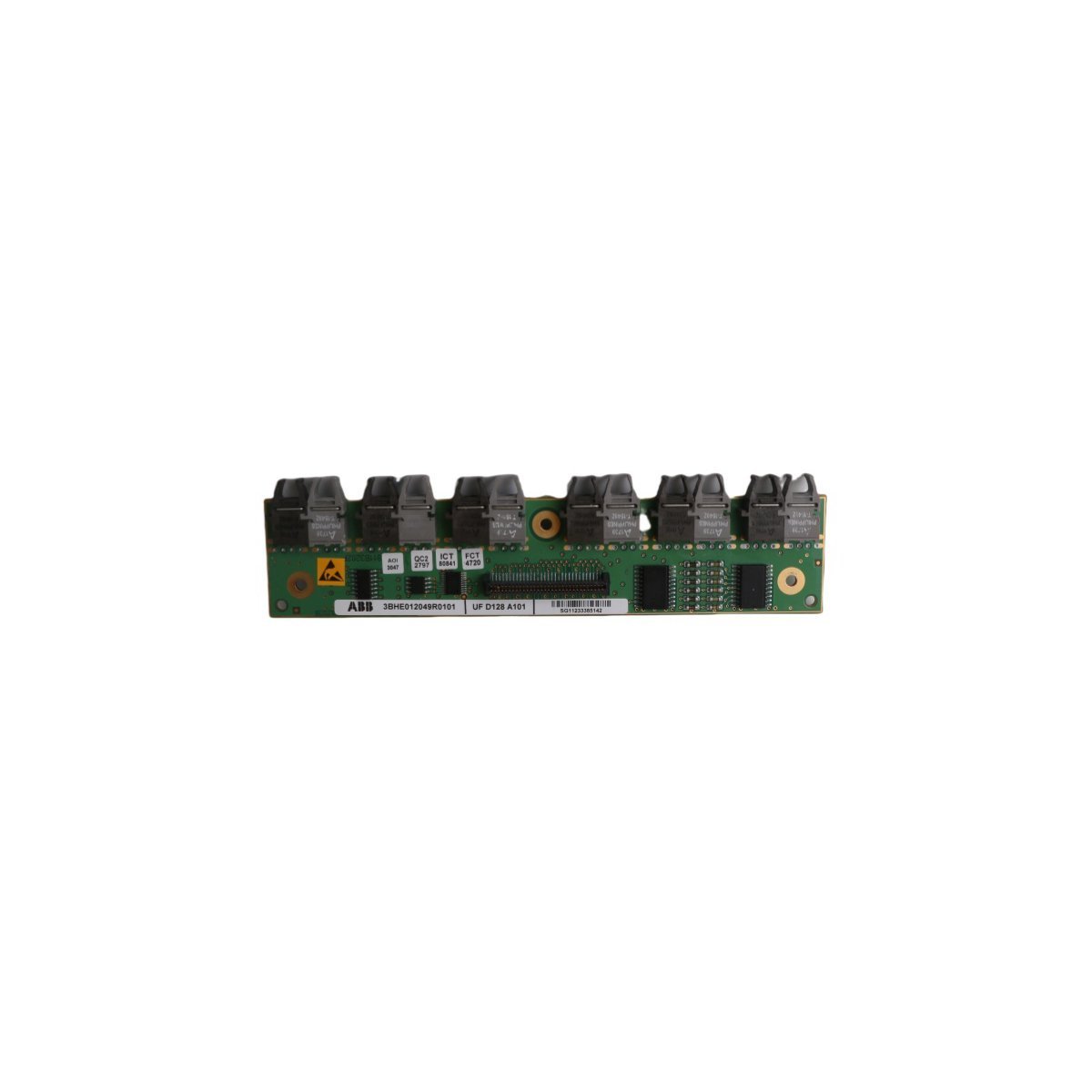
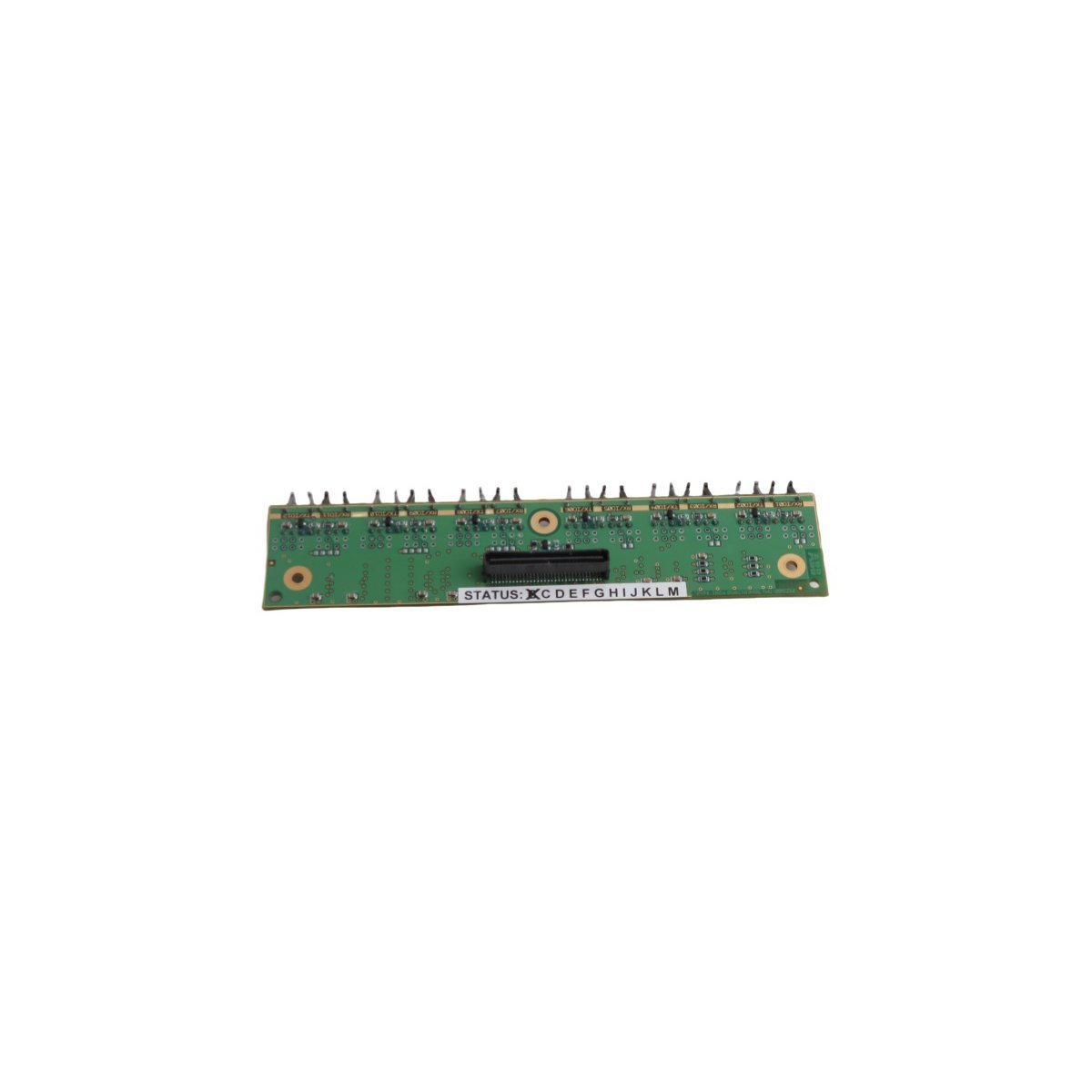
The Allen Bradley 80190-100-01-R, also cataloged as the 80190-100-01-R Fiber Optic Board, operates as a dedicated hardware component for optical signal conversion and transmission within PLC-5 network environments. The unit processes optical waveforms to establish reliable point-to-point physical links across extended industrial topologies, eliminating electromagnetic interference vulnerabilities typical of standard copper cabling.
Suffix Breakdown & Model Matrix
The model nomenclature follows structured revision tracking conventions established by the manufacturer:- 80190: Core hardware series identifier designating fiber optic transceiver and interface board architecture.
- -100: Standard bandwidth and optical wavelength variant configuration.
- -01: Revision tier indicating base hardware layout and component tolerances.
- -R: RoHS compliance designation denoting restriction of hazardous substances adherence in electronic manufacturing.
Hardware Specifications
| Parameter | Specification |
|---|---|
| Model | 80190-100-01-R |
| Brand | Allen Bradley |
| Origin | USA |
| Weight | 0.06 kg |
| Dimensions | 10.3 x 8.8 x 2 cm |
| Operating Temp | 0 deg C to 60 deg C |
| Power Consumption | 2.5 W max |
| Range of Product | PLC-5 |
| Communication Service | Ethernet router / Fiber optical interface |
| Condition | Brand New |