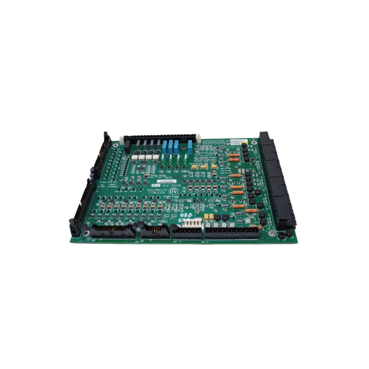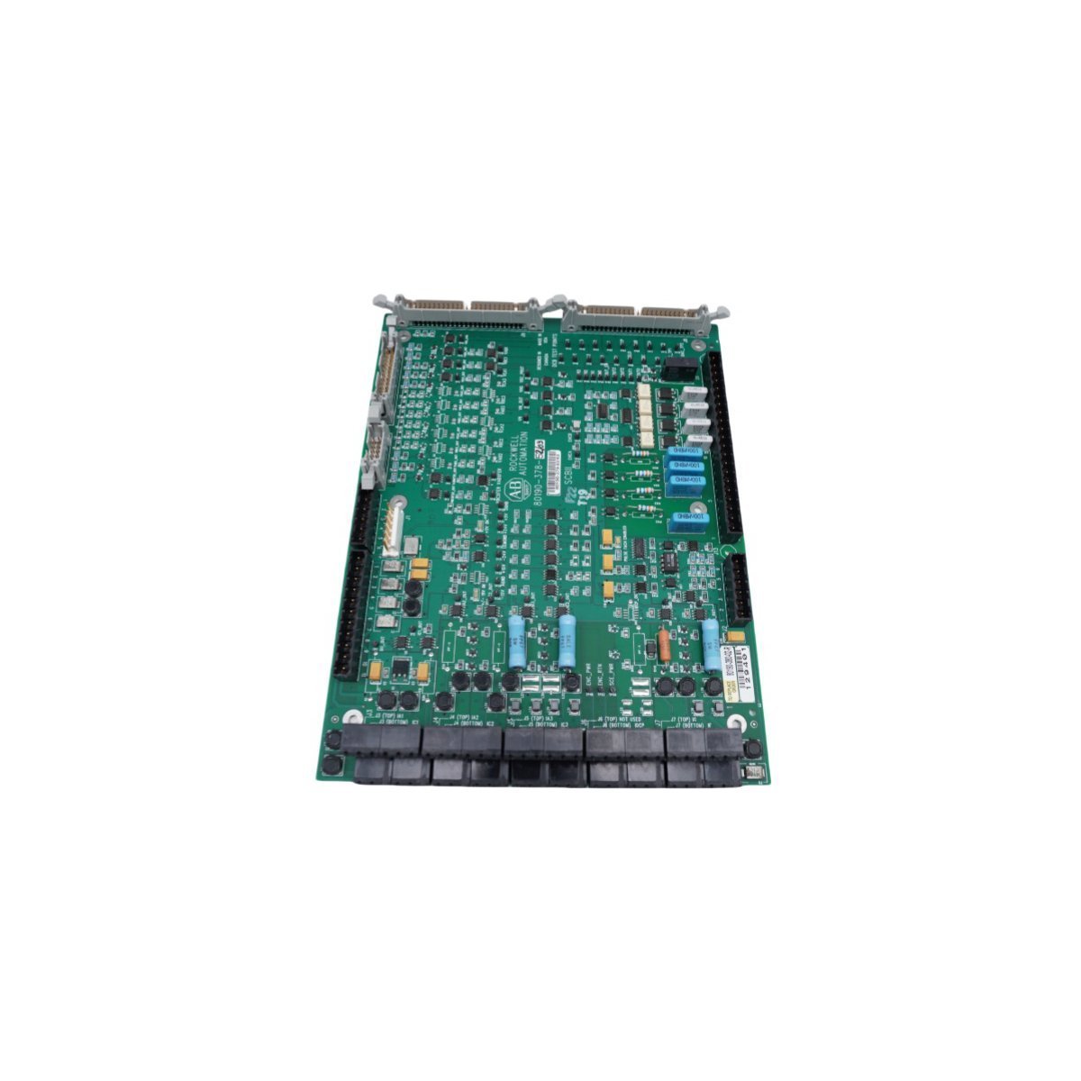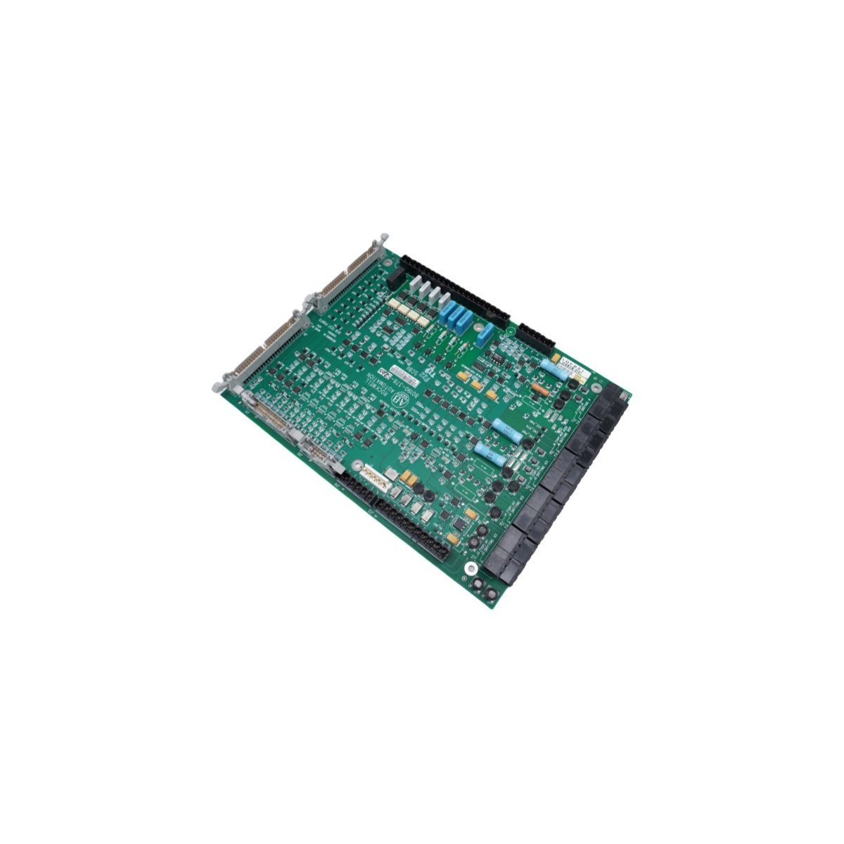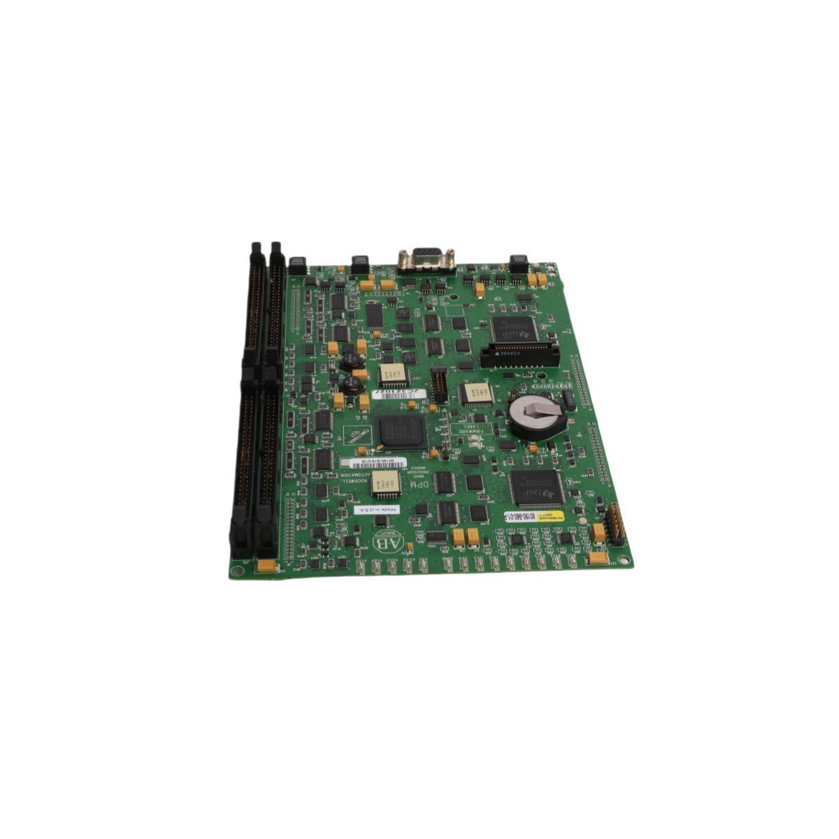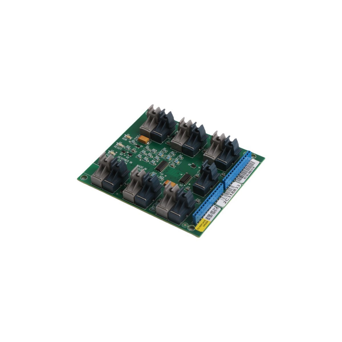
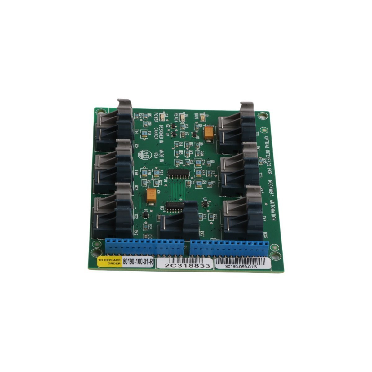
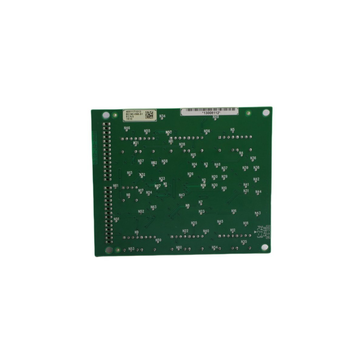
The Allen Bradley 80190-100-01-R, also cataloged as the 80190-100-01-R Fiber Optic Board, operates as a dedicated hardware component for optical signal conversion and transmission within PLC-5 network environments. The unit processes optical waveforms to establish reliable point-to-point physical links across extended industrial topologies, eliminating electromagnetic interference vulnerabilities typical of standard copper cabling.
Suffix Breakdown & Model Matrix
The model nomenclature follows structured revision tracking conventions established by the manufacturer:
80190: Core hardware series identifier designating fiber optic transceiver and interface board architecture.
-100: Standard bandwidth and optical wavelength variant configuration.
-01: Revision tier indicating base hardware layout and component tolerances.
-R: RoHS compliance designation denoting restriction of hazardous substances adherence in electronic manufacturing.
Hardware Specifications
Parameter
Specification
Model
80190-100-01-R
Brand
Allen Bradley
Origin
USA
Weight
0.06 kg
Dimensions
10.3 x 8.8 x 2 cm
Operating Temp
0 deg C to 60 deg C
Power Consumption
2.5 W max
Range of Product
PLC-5
Communication Service
Ethernet router / Fiber optical interface
Condition
Brand New
Backplane Bus Communication Velocity and Firmware Integration
Data transmission across the PLC-5 chassis interface relies on deterministic timing parameters managed by the onboard transceiver logic. The optical conversion circuitry regulates signal attenuation to maintain bit error rates below 10-12 over specified fiber attenuation windows. Firmware flash compatibility ensures alignment with legacy backplane bus communication velocity requirements, supporting multi-drop network synchronization without packet jitter escalation.
Frequently Asked Questions
Q: What are the primary hot-swap limitations when replacing this fiber optic board in an active PLC chassis?
A: Hot-swapping is restricted unless designated system slot power isolation procedures are executed. Live extraction without rack power down can induce transient voltage spikes across backplane communication pins.
Q: How does the module handle optical link loss during runtime?
A: Loss of light signal triggers an immediate hardware interrupt flag on the local bus interface, prompting the primary CPU controller to transition redundant communication loops within deterministic fallback time bounds.
Field Installation Guidelines
Observe standard electrostatic discharge (ESD) mitigation protocols prior to handling the printed circuit board assembly. Secure the unit within the designated rack slot using retention screws torqued to manufacturer specifications. Ensure optical patch cables match the correct core diameter and connector polishing parameters to prevent insertion loss exceeding nominal thresholds. Maintain bend radii above minimum thresholds for all connected fiber optic cabling.
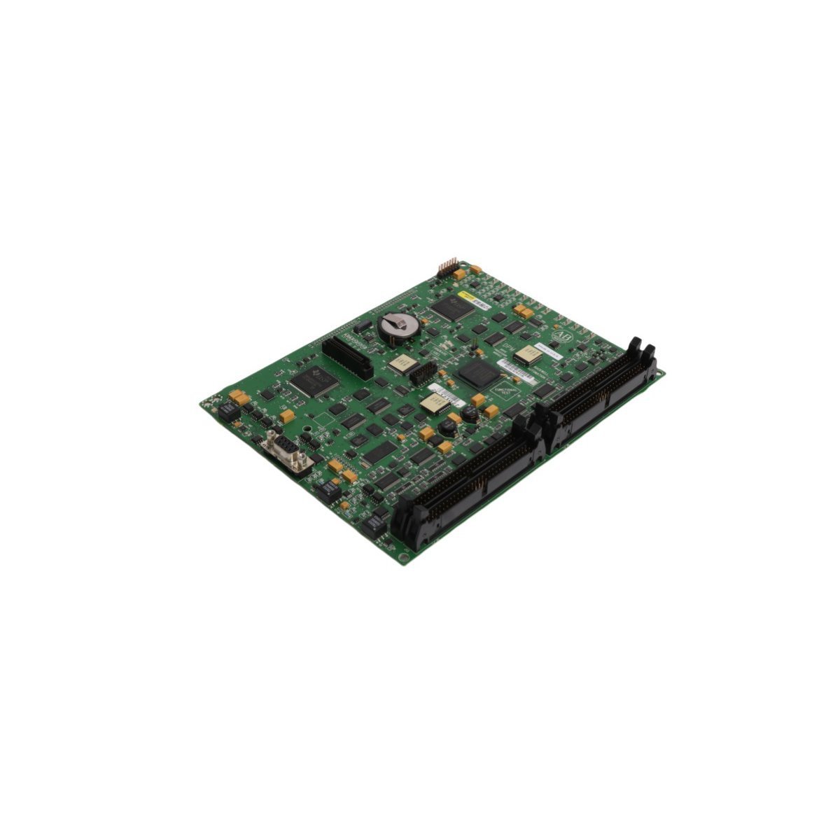
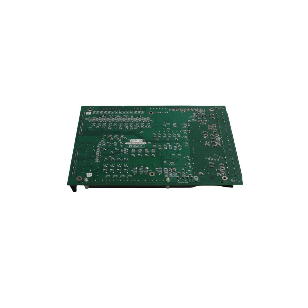
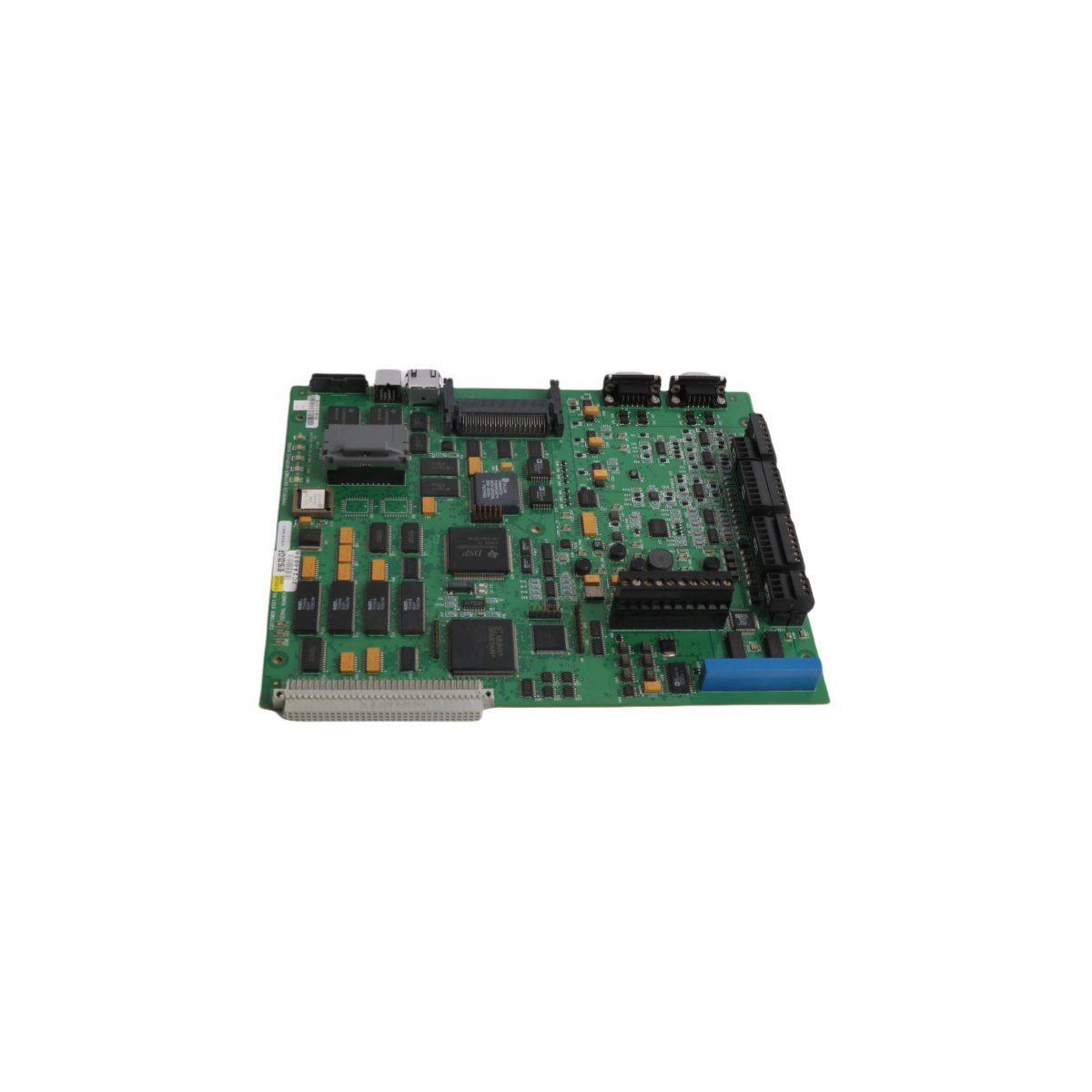
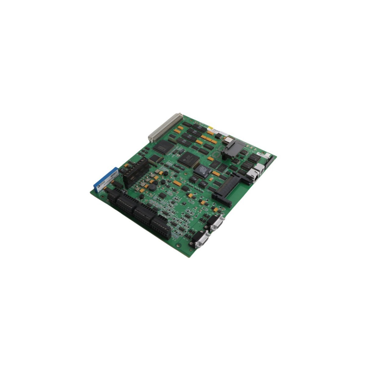
The Allen Bradley 80190-320-03-R, also cataloged as the 80190-320-03-R Control Motherboard, operates as a dedicated hardware component for system-level logic management and signal distribution within PLC-5 architecture platforms.
Hardware Specifications
Parameter
Specification
Model
80190-320-03-R
Brand
Allen Bradley
Origin
USA
Weight
0.48 kg
Dimensions
25 x 21.8 x 3.5 cm
Operating Temp
-20 deg C to 60 deg C
Power Consumption
System Backplane Dependent
Product Range
PLC-5
Industrial Control and Network Characteristics
The 80190-320-03-R utilizes backplane bus communication velocity to maintain deterministic signal paths within the chassis. Integration into automation networks supports multi-protocol data exchange, ensuring synchronization between I/O modules and the primary processor. Firmware flash compatibility allows for system version alignment, while the modular architecture facilitates scalable I/O density within the PLC-5 environment to meet specific application requirements.
Frequently Asked Questions
Q: Does the 80190-320-03-R support hot-swapping within the PLC-5 chassis?A: The module is designed for fixed installation within the backplane; hot-swapping is not recommended unless explicitly supported by the specific chassis revision and power distribution unit.Q: What are the grounding requirements for the motherboard to ensure signal integrity?A: The motherboard must be securely fastened to the chassis to establish a common ground plane, and all I/O shields must be terminated at the designated cabinet grounding point to suppress noise.
Field Installation Guidelines
Isolate all power sources to the PLC-5 chassis prior to hardware installation.
Inspect the motherboard backplane connector pins for oxidation or mechanical deformation.
Align the motherboard into the chassis guide rails and apply firm, even pressure until the backplane connector is fully seated.
Secure the board using the integrated locking mechanisms or chassis screws to ensure mechanical stability.
Connect all ribbon cables and field wiring interfaces, ensuring proper strain relief to prevent tension on the board-to-board connections.
Verify electrical continuity and ground bonding before restoring power to the system.
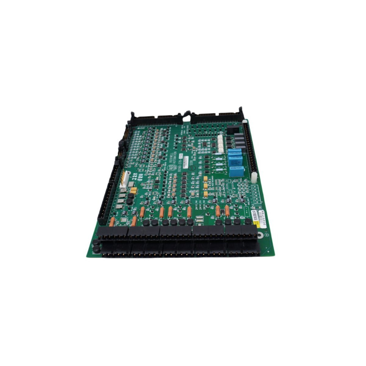
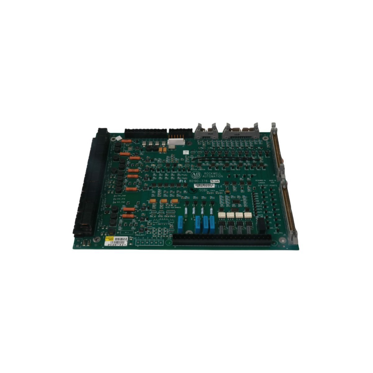
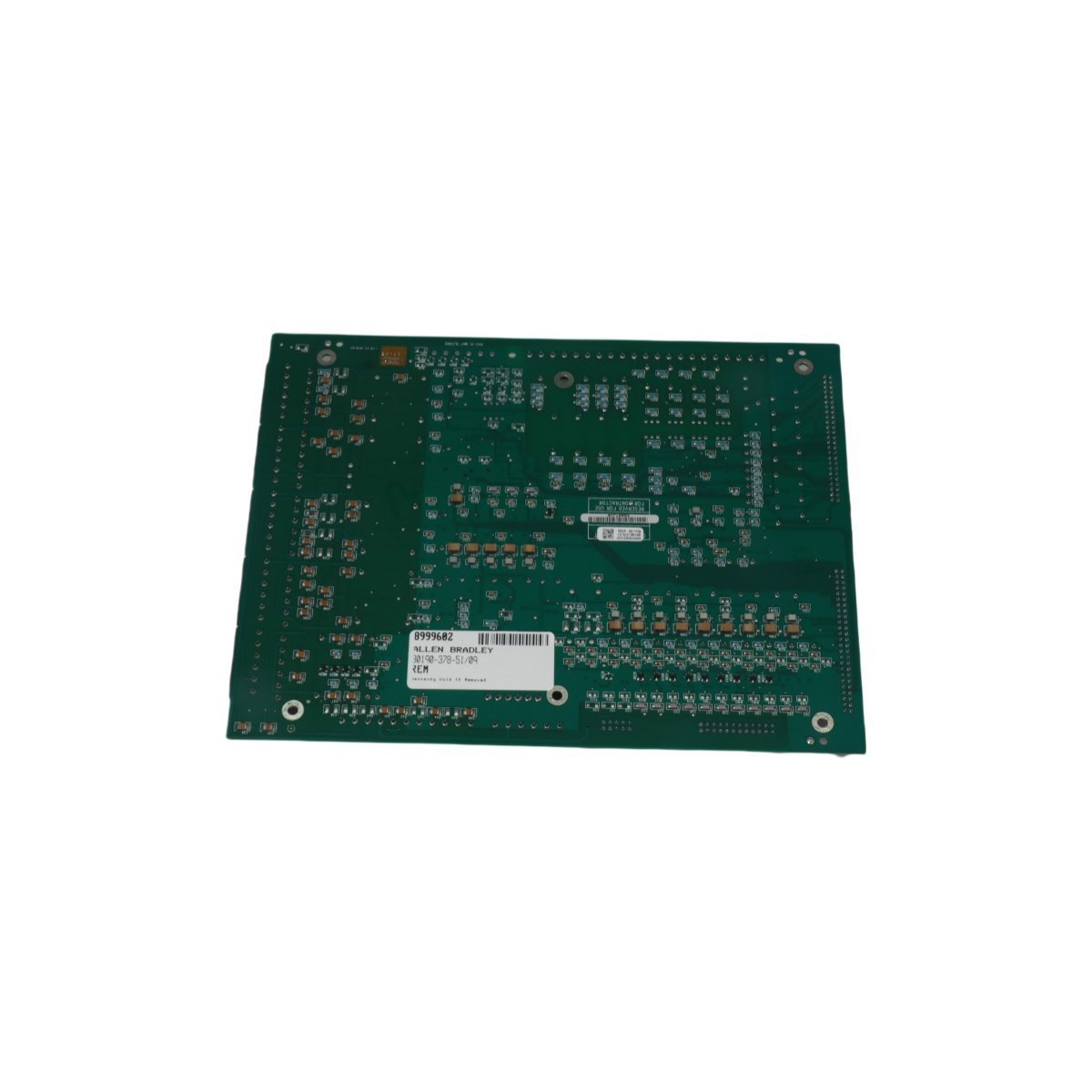
The Allen Bradley 80190-378-51, also cataloged as the 80190-378-51 PC Board, operates as a dedicated hardware component for signal processing and logic execution within PLC-5 platform networks.
Hardware Specifications
Parameter
Specification
Model
80190-378-51
Brand
Allen Bradley
Origin
USA
Weight
0.46 kg
Dimensions
27.8 x 21.4 x 2.8 cm
Operating Temp
Standard Industrial Range
Power Consumption
System Dependent
Module Type
PC Board
PLC Deterministic Network Integration
The Allen Bradley 80190-378-51 utilizes backplane bus communication protocols designed for integration with PLC-5 control architectures. The module supports deterministic network timing, ensuring low-latency state feedback and synchronization within complex I/O density configurations. Compatibility with field-programmable firmware allows for flash updates to align with evolving backplane bus communication velocity requirements, maintaining bus traffic integrity and reducing collision potential in high-speed control loops.
Frequently Asked Questions
Q: What are the restrictions regarding the installation of the 80190-378-51 in an active PLC-5 backplane?A: Ensure that the backplane power is cycled off before insertion or removal to prevent electrical arcing on the connector pins. The module must be correctly seated in the chassis slot to maintain signal integrity across the backplane bus.Q: Is this module capable of firmware field-upgrades?A: Yes, the unit supports firmware flash compatibility via the primary control bus interface. Verify the current revision against the specific PLC-5 processor requirements before initiating any update sequence.
Field Installation Guidelines
Mount the PC Board into a standard PLC-5 chassis. Ensure the mounting screws are tightened to the specified torque to guarantee a secure electrical chassis ground connection.
Avoid exposing the component to electrostatic discharge (ESD). Utilize a grounded wrist strap when handling the board.
Ensure all backplane pins are free of debris or oxidation before installation.
Maintain ambient operating temperature within the specified industrial limits to prevent thermal degradation of on-board components.
Verify that the backplane power supply capacity is sufficient for the total I/O density load when the module is initialized.
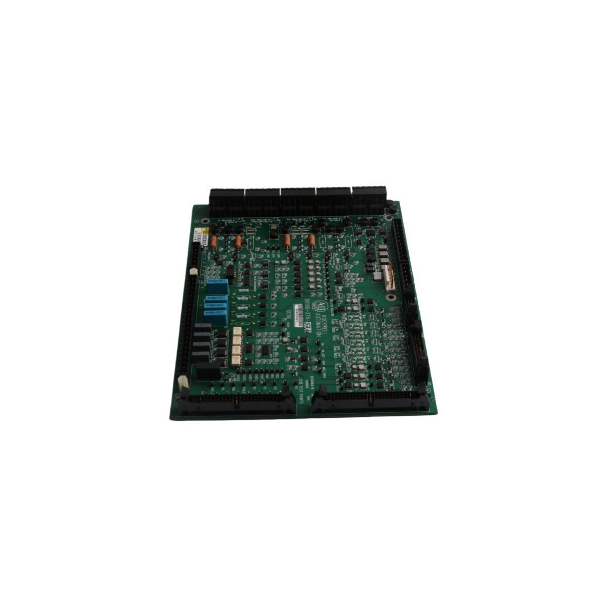
The Allen Bradley 80190-378-52, also cataloged as the 80190-378-52 Inverter Control Board, operates as a dedicated hardware component for inverter logic processing and signal regulation within PLC-5 platform networks.
Hardware Specifications
Parameter
Specification
Model
80190-378-52
Brand
Allen Bradley
Origin
USA
Weight
0.46 kg
Dimensions
27.8 x 21.4 x 2.8 cm
Operating Temp
Standard Industrial Range
Power Consumption
System Dependent
Module Type
Inverter Control Board
Industrial Control System Integration
The Allen Bradley 80190-378-52 utilizes backplane bus communication protocols designed for integration with PLC-5 control architectures. The module supports deterministic network timing, ensuring low-latency state feedback and synchronization within complex I/O density configurations. Compatibility with field-programmable firmware allows for flash updates to align with evolving backplane bus communication velocity requirements, maintaining bus traffic integrity and reducing collision potential in high-speed control loops.
Frequently Asked Questions
Q: What are the restrictions regarding the installation of the 80190-378-52 in an active PLC-5 backplane?A: Ensure that backplane power is cycled off before module insertion or removal to prevent electrical arcing on connector pins. The module must be firmly seated in the chassis slot to maintain signal integrity across the backplane bus.Q: Is this module capable of firmware field-upgrades?A: Yes, the unit supports firmware flash compatibility via the primary control bus interface. Verify the current revision against the specific PLC-5 processor requirements before initiating any update sequence.
Field Installation Guidelines
Mount the control board into the designated PLC-5 chassis slot. Tighten the mounting screws to the specified torque to guarantee a secure electrical chassis ground connection.
Avoid exposing the component to electrostatic discharge (ESD). Utilize a grounded wrist strap at all times when handling the board.
Ensure all backplane pins are clean and free of debris or oxidation prior to installation.
Maintain ambient operating temperature within the specified industrial limits to prevent thermal degradation of on-board components.
Verify that the backplane power supply capacity is sufficient for the total I/O density load when the module is fully initialized.
Configured for high-speed signal transmission and communication management in motor control networks, the Allen Bradley 80190-520-01-R (80190-520-01-R Fiber Optic Board) provides direct physical and electrical execution for optical data conversion.
Hardware Specifications
Parameter
Specification
Model
80190-520-01-R
Brand
Allen Bradley
Origin
USA
Weight
0.46 kg
Dimensions
27.8 x 21.4 x 2.8 cm
Operating Temp
Standard industrial range
Power Consumption
System dependent
Module Type
Fiber Optic Board
Control Architecture Integration
The Allen Bradley 80190-520-01-R utilizes backplane bus communication protocols to maintain deterministic data flow within SMC-Flex motor control platforms. The module supports I/O density scaling, allowing for seamless integration into multi-axis drive configurations. Its firmware flash compatibility ensures alignment with host processor timing requirements, enabling precise control of optical signal modulation. This hardware maintains bus traffic integrity and synchronization across networked motor control systems.
Frequently Asked Questions
Q: What are the physical constraints for fiber optic cable termination on the 80190-520-01-R?A: Ensure that the minimum bend radius of the fiber optic media is maintained to prevent signal attenuation. Terminations must be clean and free of contamination to avoid optical link errors.Q: Is this module compatible with live-insertion (hot-swap) procedures in the controller chassis?A: No, the module requires the backplane power to be de-energized before installation or removal to prevent potential electrical damage to the bus interface circuitry and connector pins.
Field Installation Guidelines
Disconnect all primary power to the controller chassis before attempting to install or remove the fiber optic board.
Utilize an anti-static wrist strap during handling to prevent electrostatic discharge damage to internal logic components.
Verify that optical transceivers are clean and free of dust before connecting fiber media.
Secure the module using the built-in chassis fasteners to ensure a proper ground plane connection.
Conduct a full system diagnostic check after installation to confirm that the optical communication link is established and error-free.
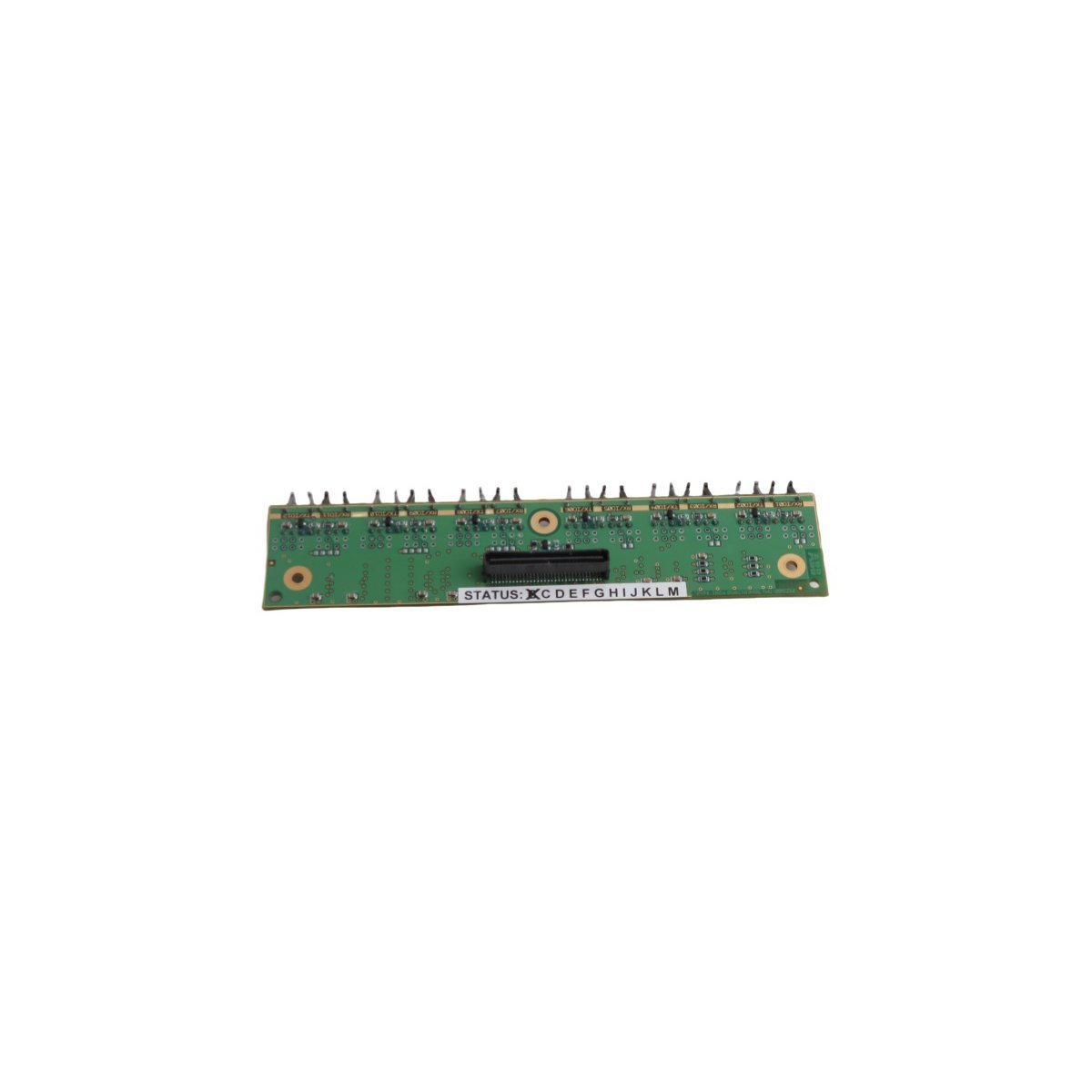
The Allen-Bradley 80190-380-01-R is a PLC-5 system analog control board module for precision manufacturing automation. Brand New and Original Stock available for Global Shipping.
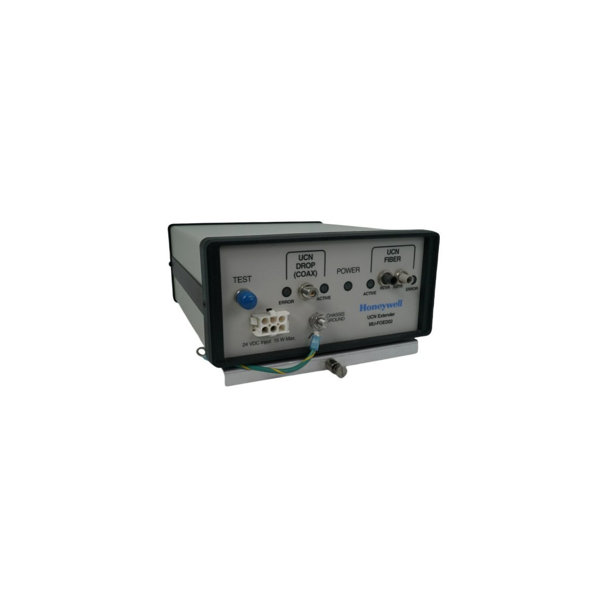
The Honeywell MU-FOED02 51197564-200 is a high-performance UCN Fiber Optic Extender designed for the MU-T Series DCS. It enables reliable, long-distance signal transmission and EMI immunity within industrial networks. This 1.66kg module supports MODBUS-TCP and OPC-UA, ensuring seamless integration and superior data integrity for complex automation systems.
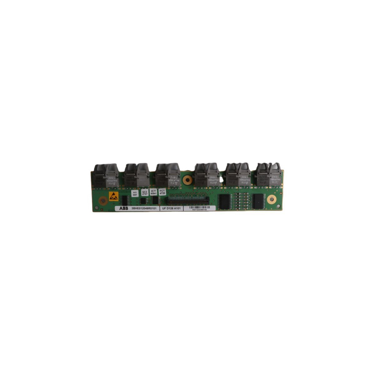
The ABB 3BHE012049R0101 UFD128A101 is a high-speed 1Gbps optical module designed for UNITROL Excitation Systems. Featuring a 1310nm wavelength and LC connector, this Swedish-made component ensures EMI-free data transmission and long-distance connectivity for advanced Distributed Control Systems.
The ICS Triplex T8314C is a conformal-coated Fiber Optic Tx/Rx Unit for Trusted TMR systems. It converts PECL signals to single-mode optical data, enabling secure, long-distance communication between controller and expander chassis in SIL 3 safety applications.
The Siemens 6GK1503-2CB00 OLM/G11 V4.0 converts PROFIBUS RS485 signals to glass fiber optics.Features 12 Mbit/s speed support, BFOC sockets, and a 24V DC input for reliable industrial networking.
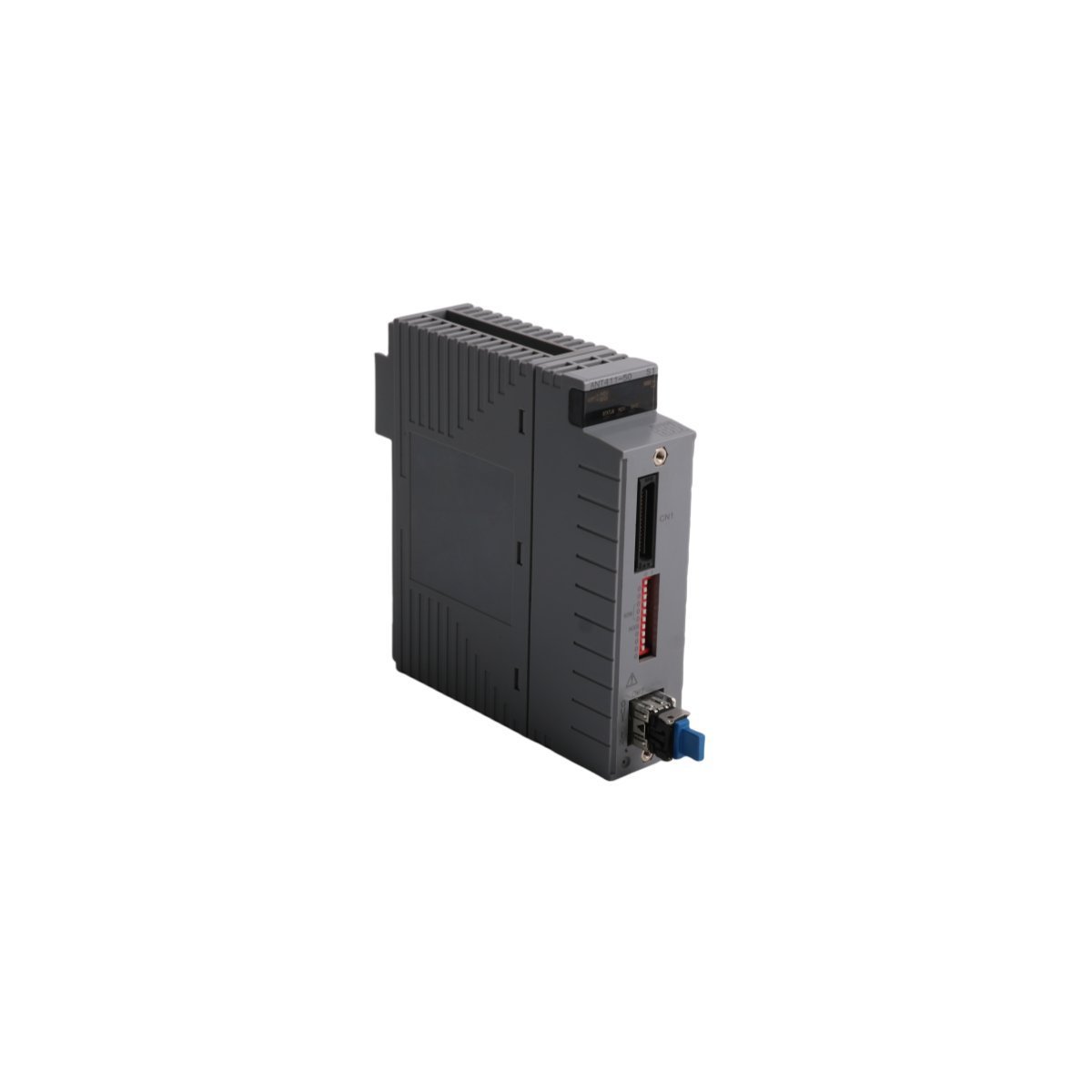
The Yokogawa ANT411-50 S1 is an optical ESB bus repeater master module for CENTUM VP. It enables high-speed, EMI-immune communication between control stations and remote I/O over distances up to 5km, supporting full redundancy for mission-critical DCS networks.
We are committed to protecting your privacy. The information collected here is strictly used to provide the requested quotes, technical support, and relevant industrial automation solutions.