Sale!
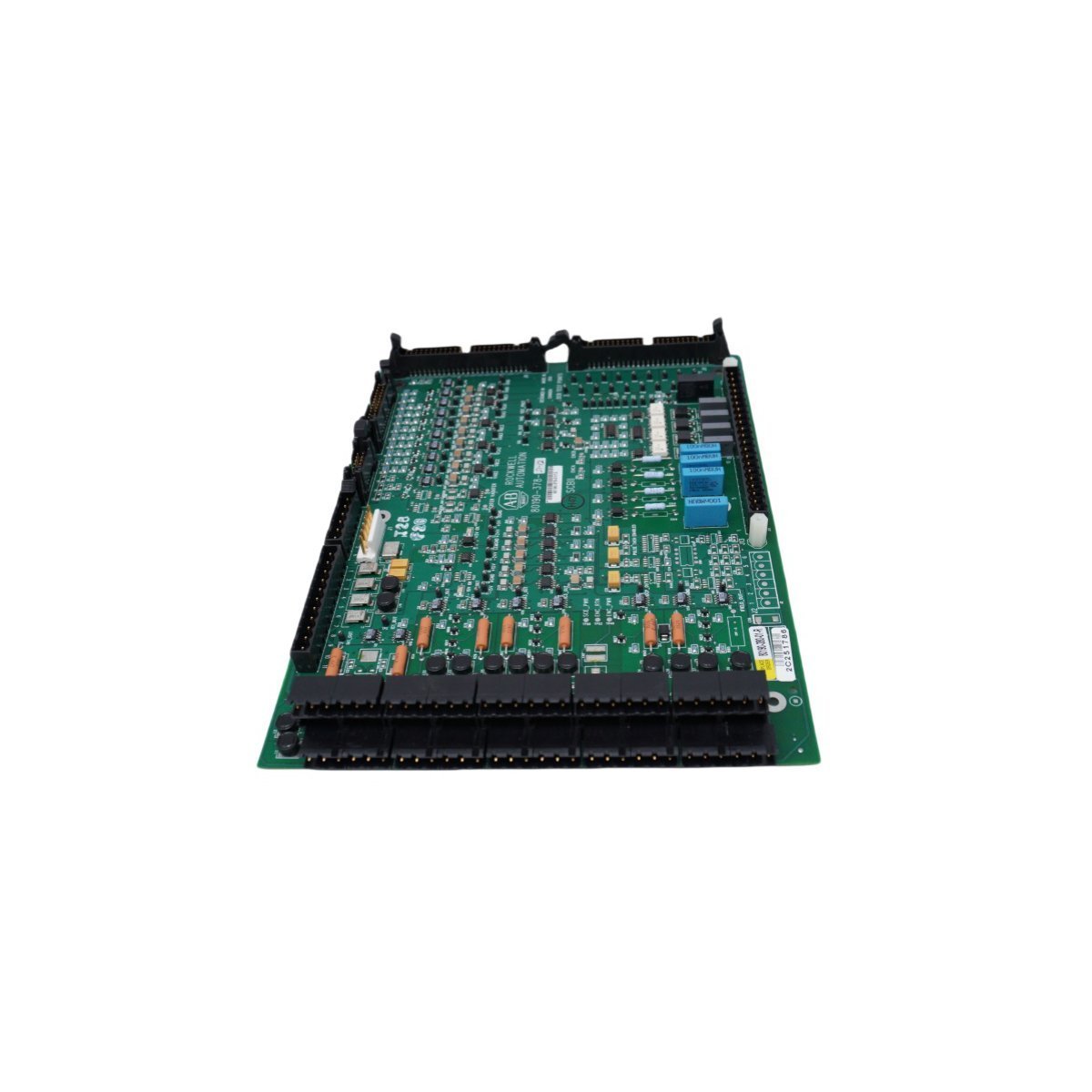
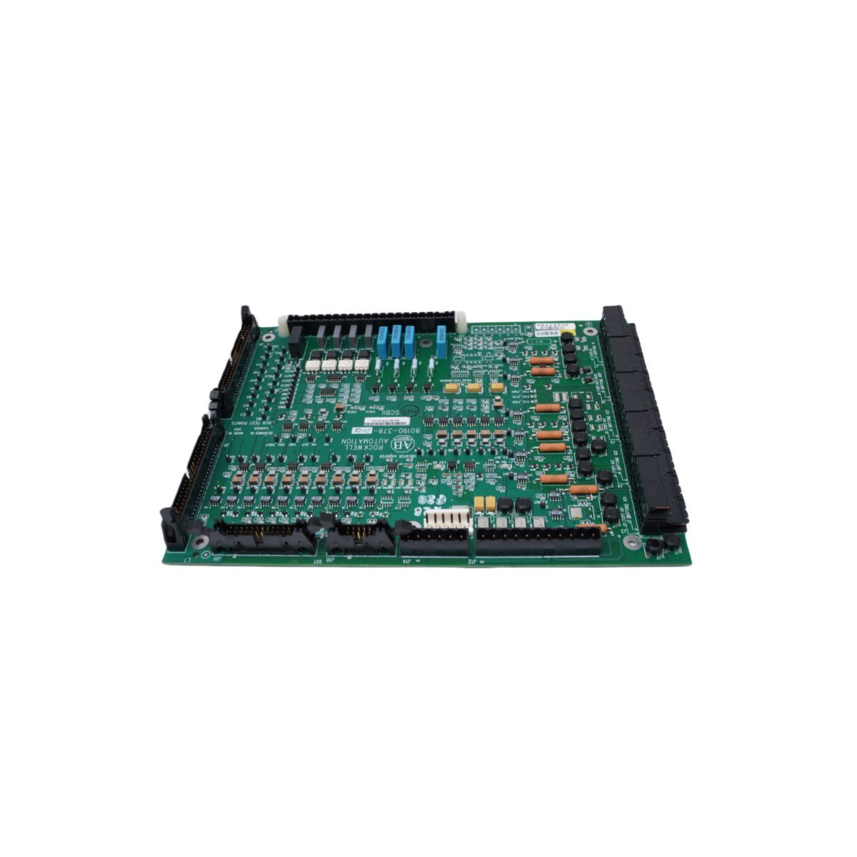
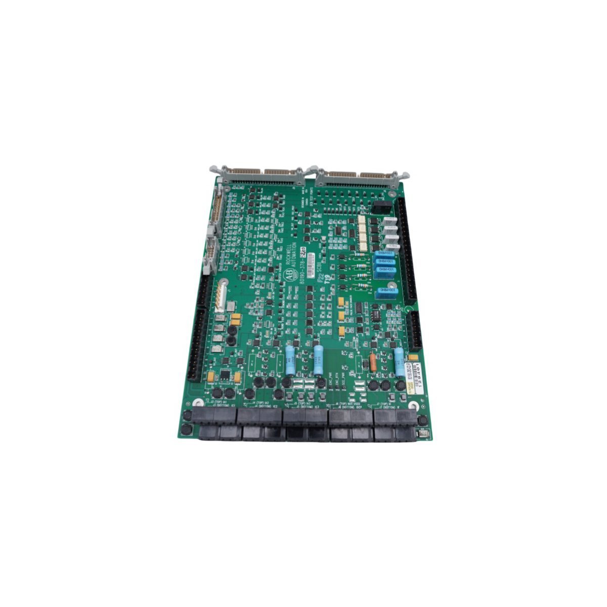
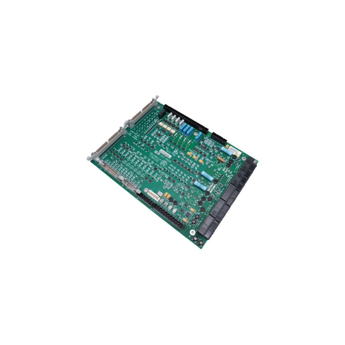
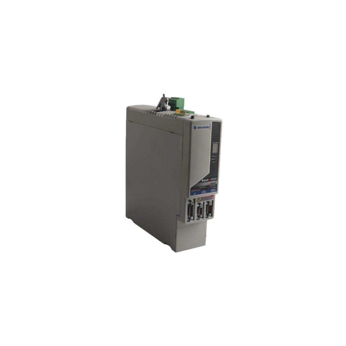
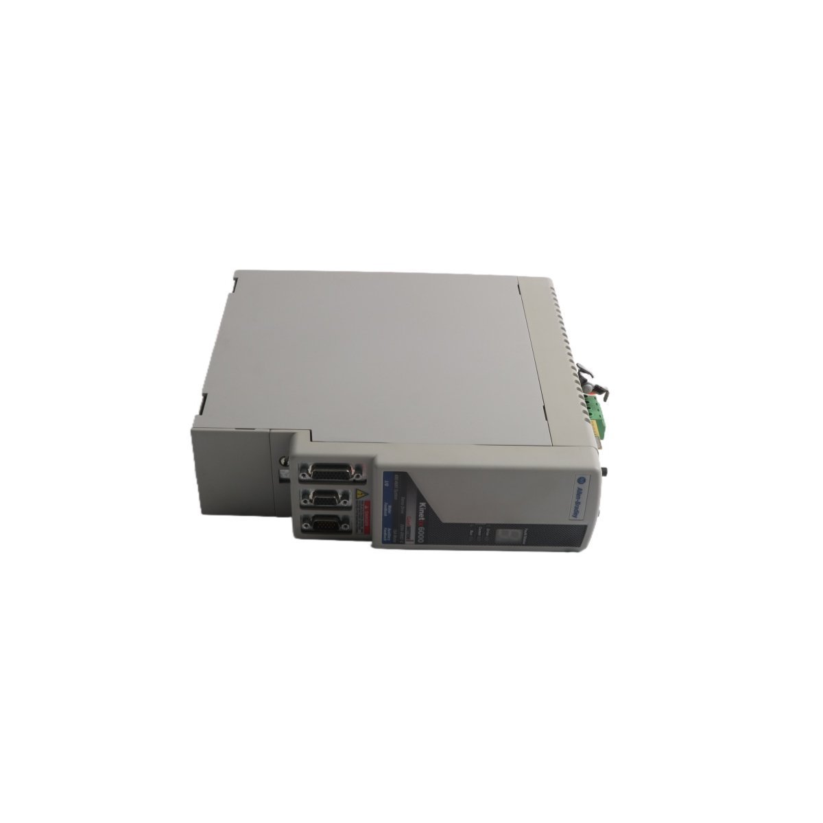
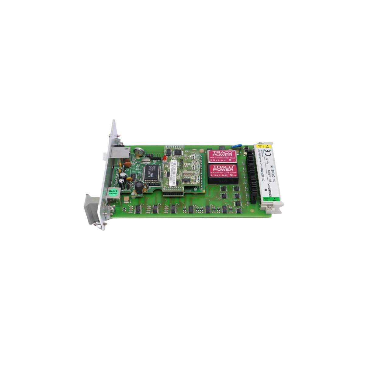
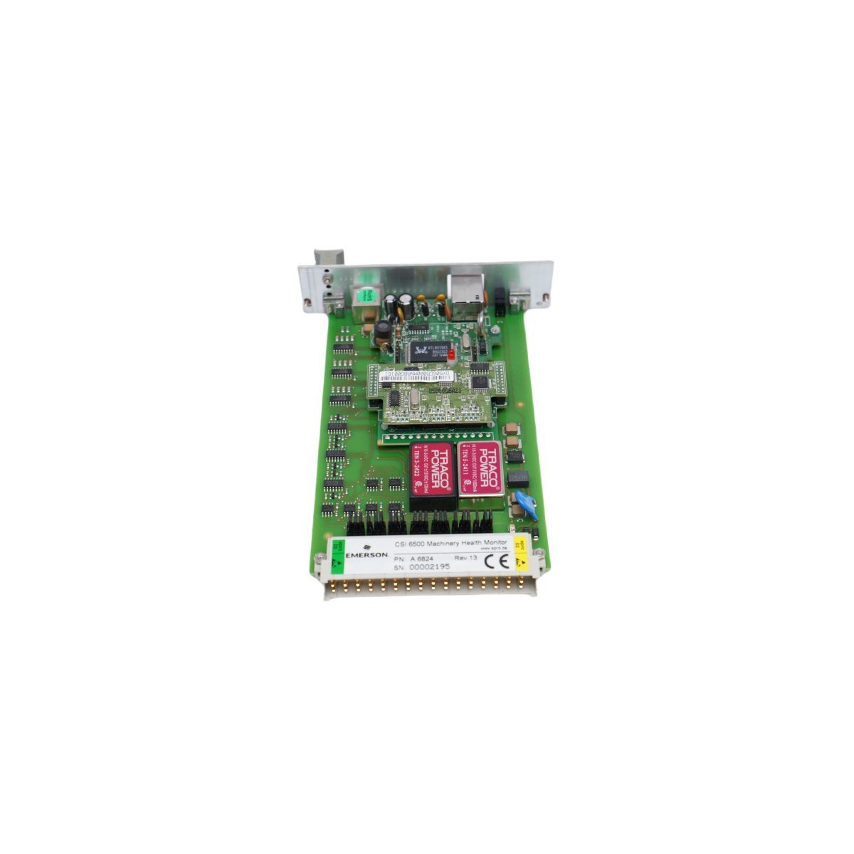
Allen Bradley 80190-378-51 PC Board
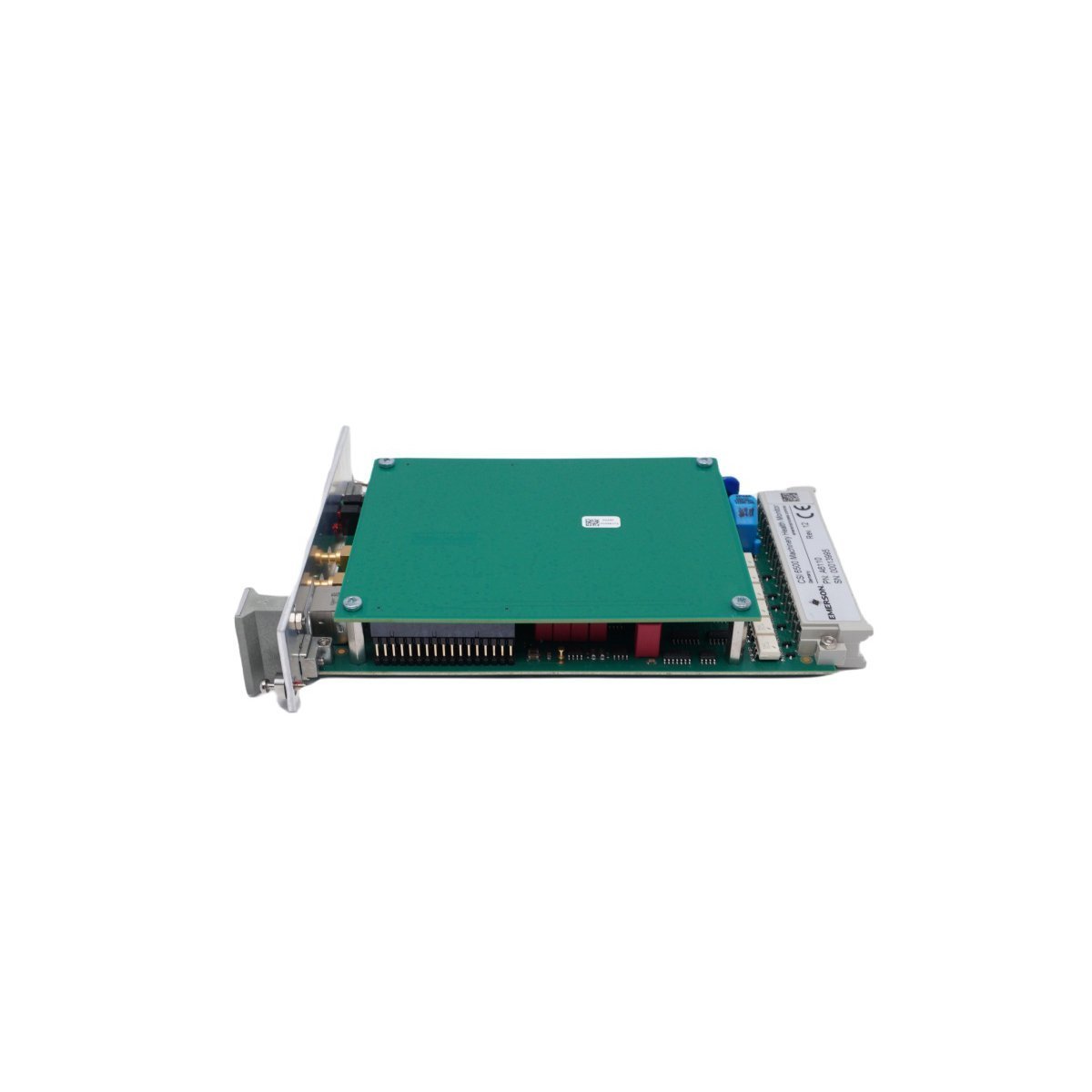
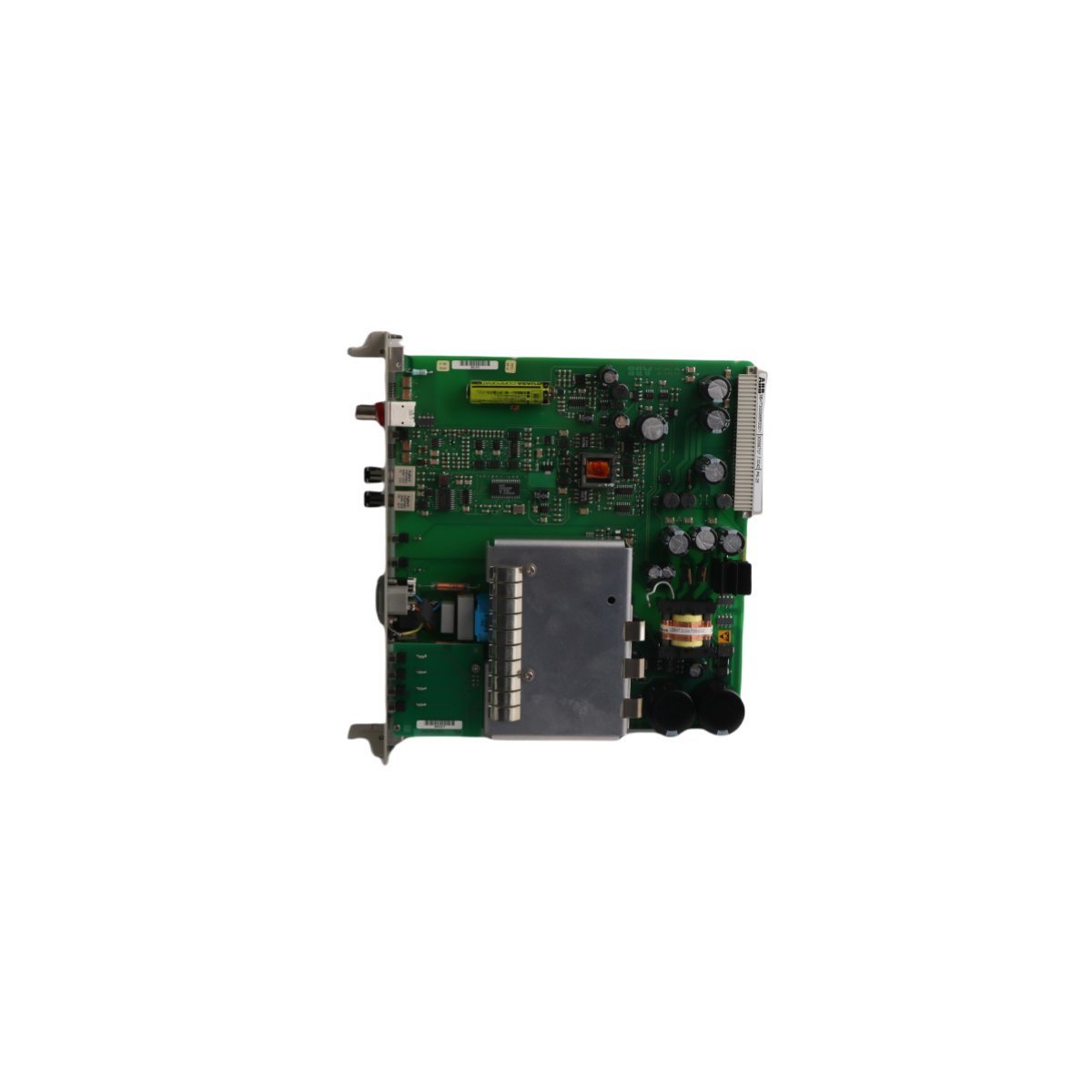
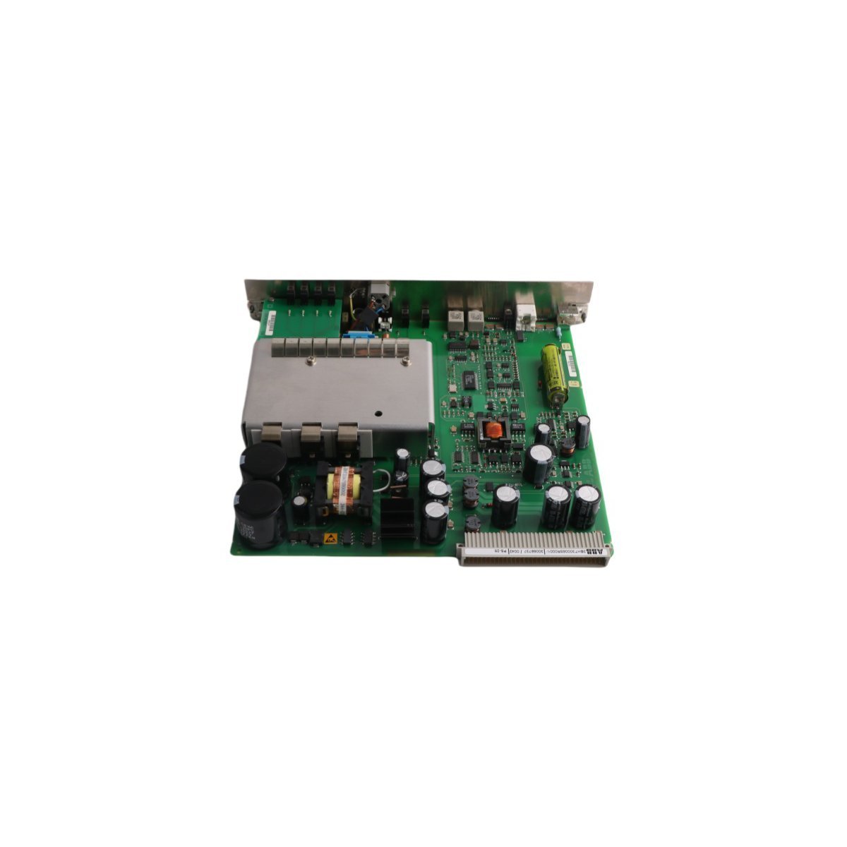
The Allen Bradley 80190-378-51, also cataloged as the 80190-378-51 PC Board, operates as a dedicated hardware component for signal processing and logic execution within PLC-5 platform networks.
Hardware Specifications
| Parameter | Specification |
|---|---|
| Model | 80190-378-51 |
| Brand | Allen Bradley |
| Origin | USA |
| Weight | 0.46 kg |
| Dimensions | 27.8 x 21.4 x 2.8 cm |
| Operating Temp | Standard Industrial Range |
| Power Consumption | System Dependent |
| Module Type | PC Board |
PLC Deterministic Network Integration
The Allen Bradley 80190-378-51 utilizes backplane bus communication protocols designed for integration with PLC-5 control architectures. The module supports deterministic network timing, ensuring low-latency state feedback and synchronization within complex I/O density configurations. Compatibility with field-programmable firmware allows for flash updates to align with evolving backplane bus communication velocity requirements, maintaining bus traffic integrity and reducing collision potential in high-speed control loops.Frequently Asked Questions
Q: What are the restrictions regarding the installation of the 80190-378-51 in an active PLC-5 backplane?A: Ensure that the backplane power is cycled off before insertion or removal to prevent electrical arcing on the connector pins. The module must be correctly seated in the chassis slot to maintain signal integrity across the backplane bus.Q: Is this module capable of firmware field-upgrades?A: Yes, the unit supports firmware flash compatibility via the primary control bus interface. Verify the current revision against the specific PLC-5 processor requirements before initiating any update sequence.Field Installation Guidelines
- Mount the PC Board into a standard PLC-5 chassis. Ensure the mounting screws are tightened to the specified torque to guarantee a secure electrical chassis ground connection.
- Avoid exposing the component to electrostatic discharge (ESD). Utilize a grounded wrist strap when handling the board.
- Ensure all backplane pins are free of debris or oxidation before installation.
- Maintain ambient operating temperature within the specified industrial limits to prevent thermal degradation of on-board components.
- Verify that the backplane power supply capacity is sufficient for the total I/O density load when the module is initialized.