


Sale!
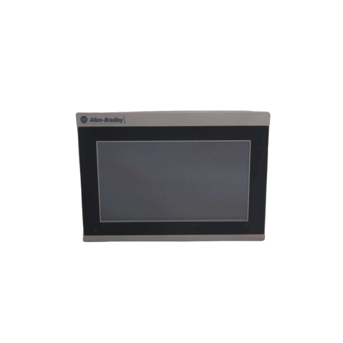
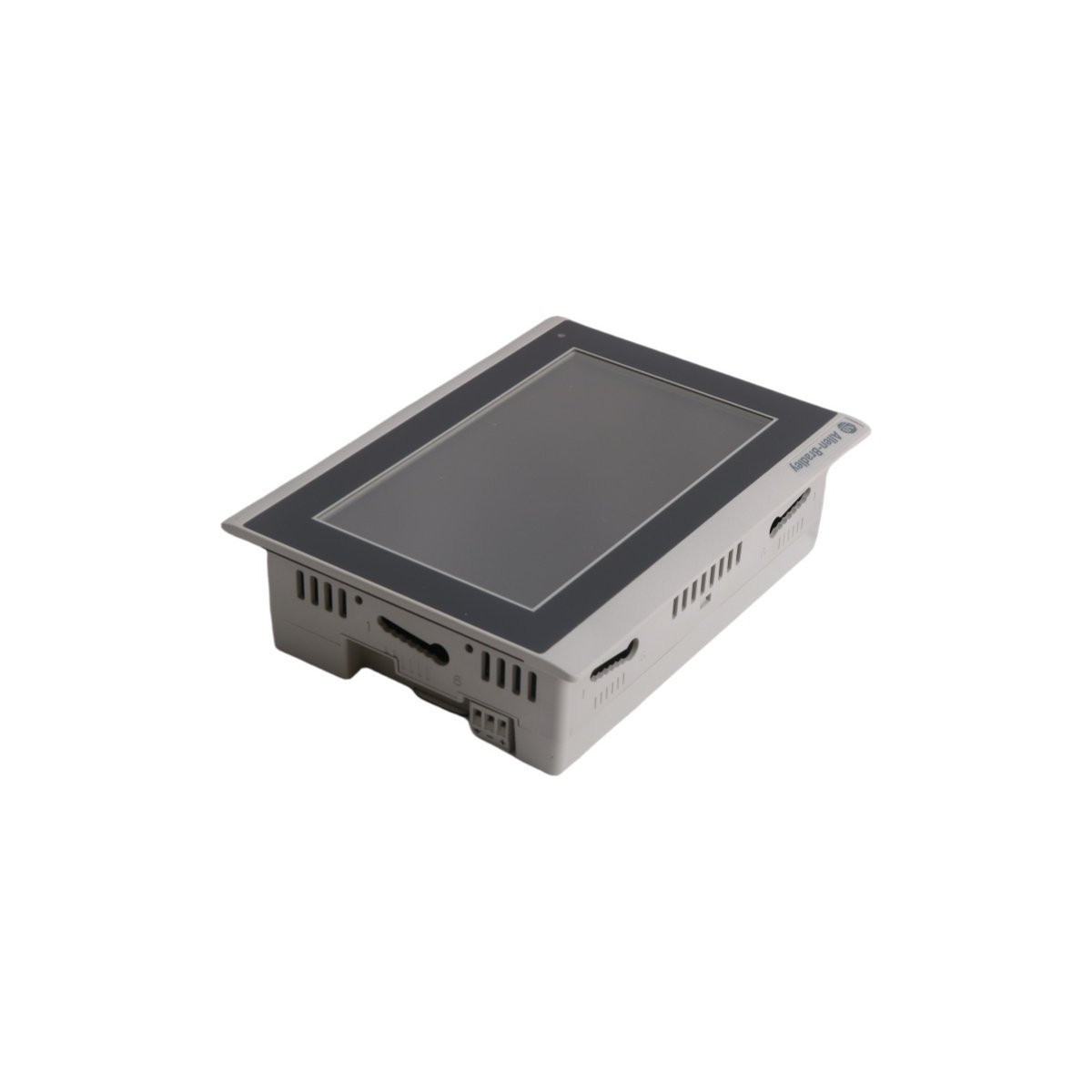
Allen-Bradley 2711R-T7T PanelView 800 Graphic Terminal
The Allen-Bradley 2711R-T7T is a 7-inch PanelView 800 HMI featuring a high-resolution touchscreen, extensive protocol support, and robust integration for industrial control systems.
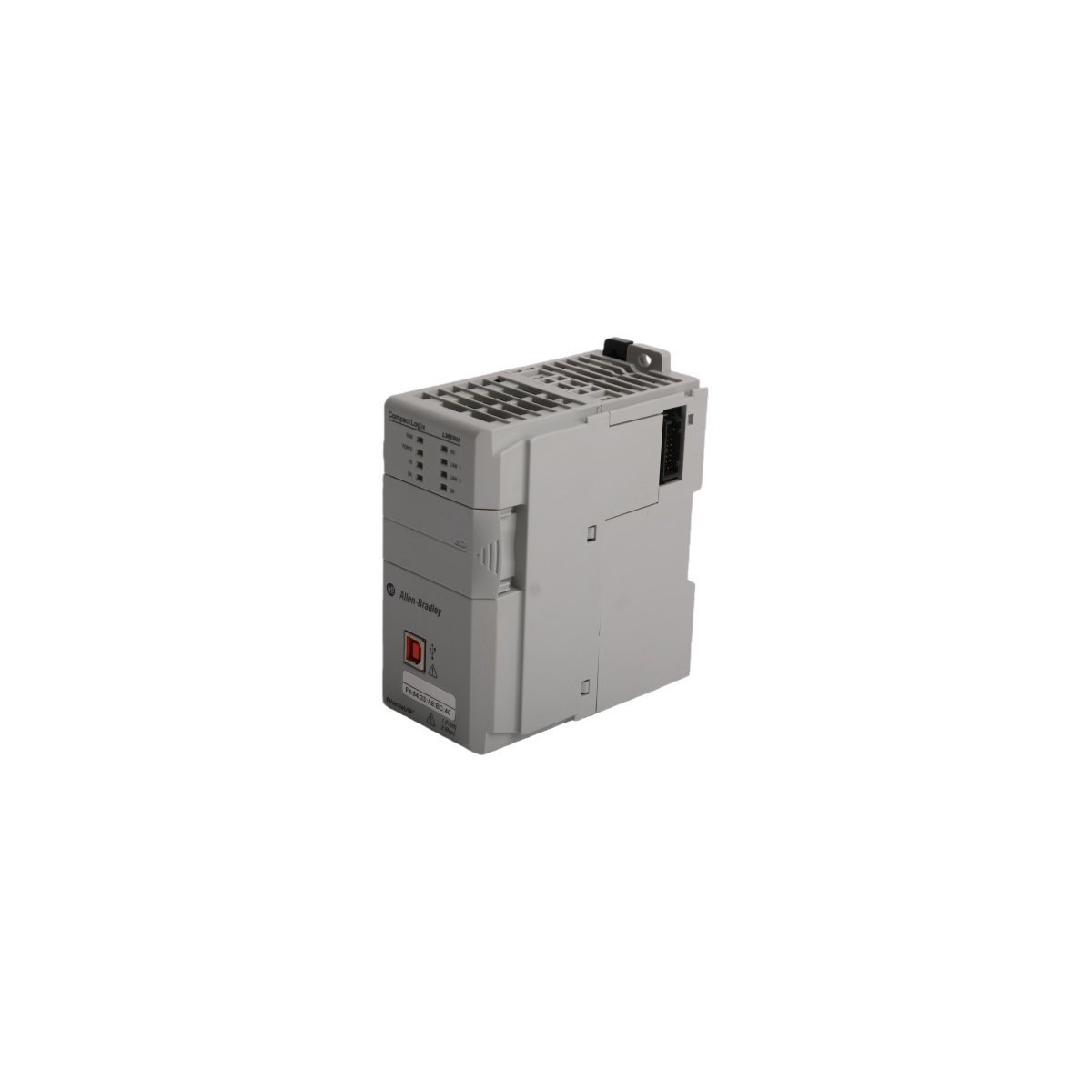
The Allen-Bradley 2094-BM02-S, also cataloged as the 2094-BM02-S Servo Drive, operates as a dedicated hardware component for multi-axis motion control execution within ControlLogix platforms. The hardware acts as a modular inverter node mounted directly onto a shared integrated power rail system. It modulates raw DC link energy into high-frequency pulse-width modulation (PWM) power vectors to regulate the angular positioning, velocity, and torque outputs of synchronized permanent magnet synchronous motors.
| Parameter | Specification |
|---|---|
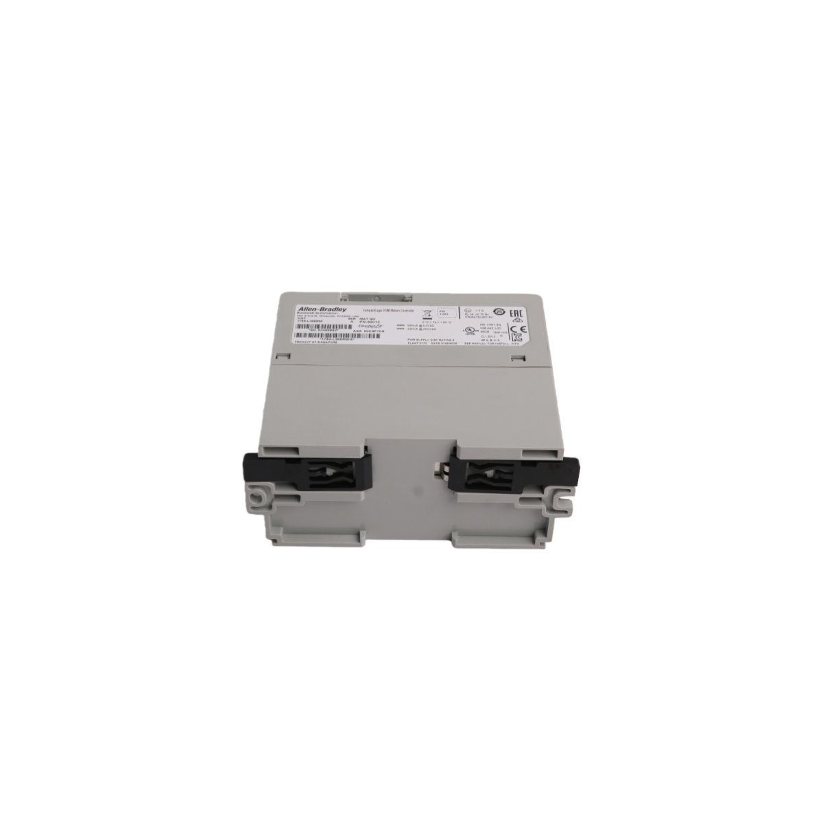
| Model | 2094-BM02-S |
| Brand | Allen-Bradley |
| Origin | USA |
| Weight | 0.9 kg |
| Dimensions | 3.5 x 13 x 14.5 cm |
| Operating Temp | 0 to +50 deg C (Standard Industrial Range) |
| Power Consumption | 650 VDC nominal input / 115 Ohm internal shunt resistor |
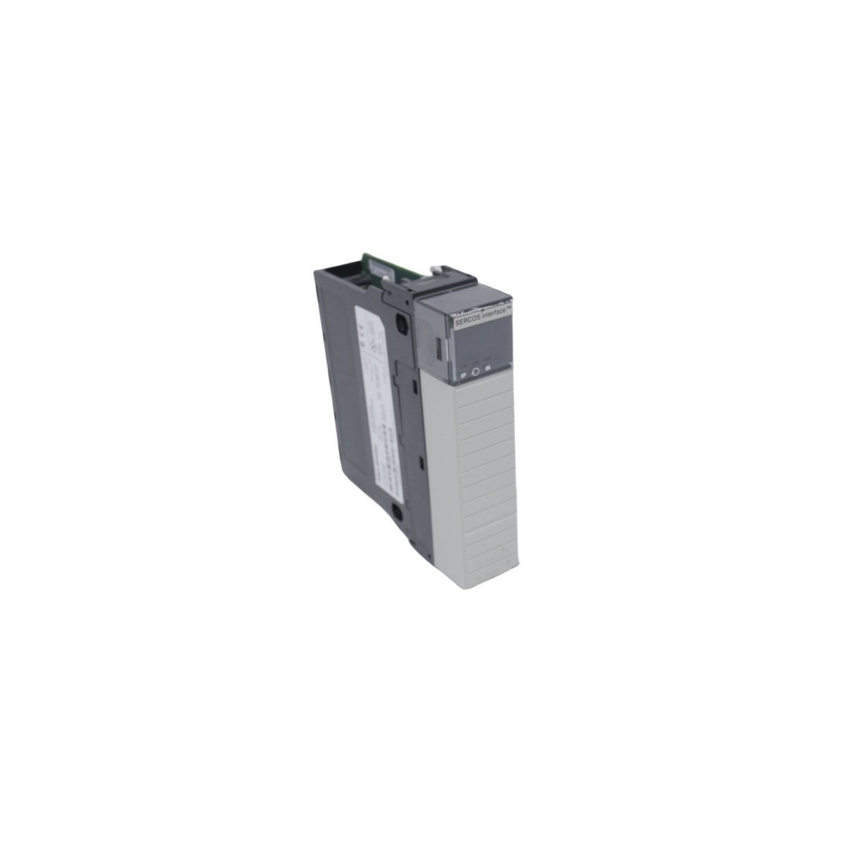
| Module Type | Servo Drive (Axis Module) |
| Product Range | ControlLogix / Kinetix 6000 |
| System Classification | PLC Motion Control |
| Continuous Current | 10.3 A (RMS), 14.6 A (Sine Peak) |
| Velocity Loop Bandwidth | 500 Hz |
| Current Loop Frequency | 1300 Hz |
| Efficiency Rating | 98% |
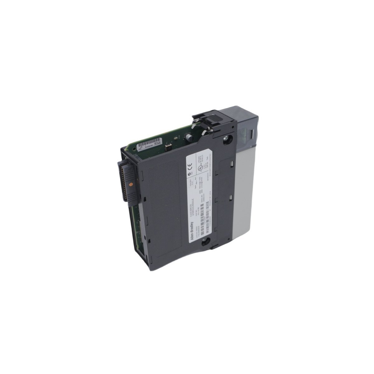
The Allen-Bradley 2094-BM02-S interacts directly over backplane bus communication velocity networks to achieve microsecond-level synchronization across adjacent drive modules. The hardware features deterministic network compatibility, letting control processors command motion trajectories with minimal jitter. It supports peak enhancement technology, scaling the nominal inverter output profile from a standard 150% threshold up to 250% during peak torque demands. This scaling permits rapid rotor acceleration and deceleration profiles without triggering overcurrent trips. Integrated Safe-Torque Off (STO) hardware circuits provide independent physical galvanic control paths, disabling gating signals to the output power transistors to prevent unexpected motor rotation during active maintenance states.
Q: What are the backplane current and configuration limits when expanding axis modules on a single rail?
A: The module must be inserted into an authorized Kinetix 6000 power rail, supporting up to seven axis modules alongside one master power module. The cumulative peak current draw must not exceed the structural rating of the shared copper backplane link.
Q: Is this hardware compatible with live hot-swapping procedures?
A: No. The shared 650 VDC bus lines pose arc-flash and component damage hazards. System DC bus voltage must be entirely drained and verified below safe thresholds before seating or unseating the module from the rail structure.
Q: Can the internal 115 Ohm shunt resistor handle high-inertia braking loads?
A: The internal shunt resistor is designed for short-duration thermal dissipation. High-inertia or cyclic deceleration applications require an external, isolated shunt module to prevent DC bus overvoltage faults.


We are committed to protecting your privacy. The information collected here is strictly used to provide the requested quotes, technical support, and relevant industrial automation solutions.