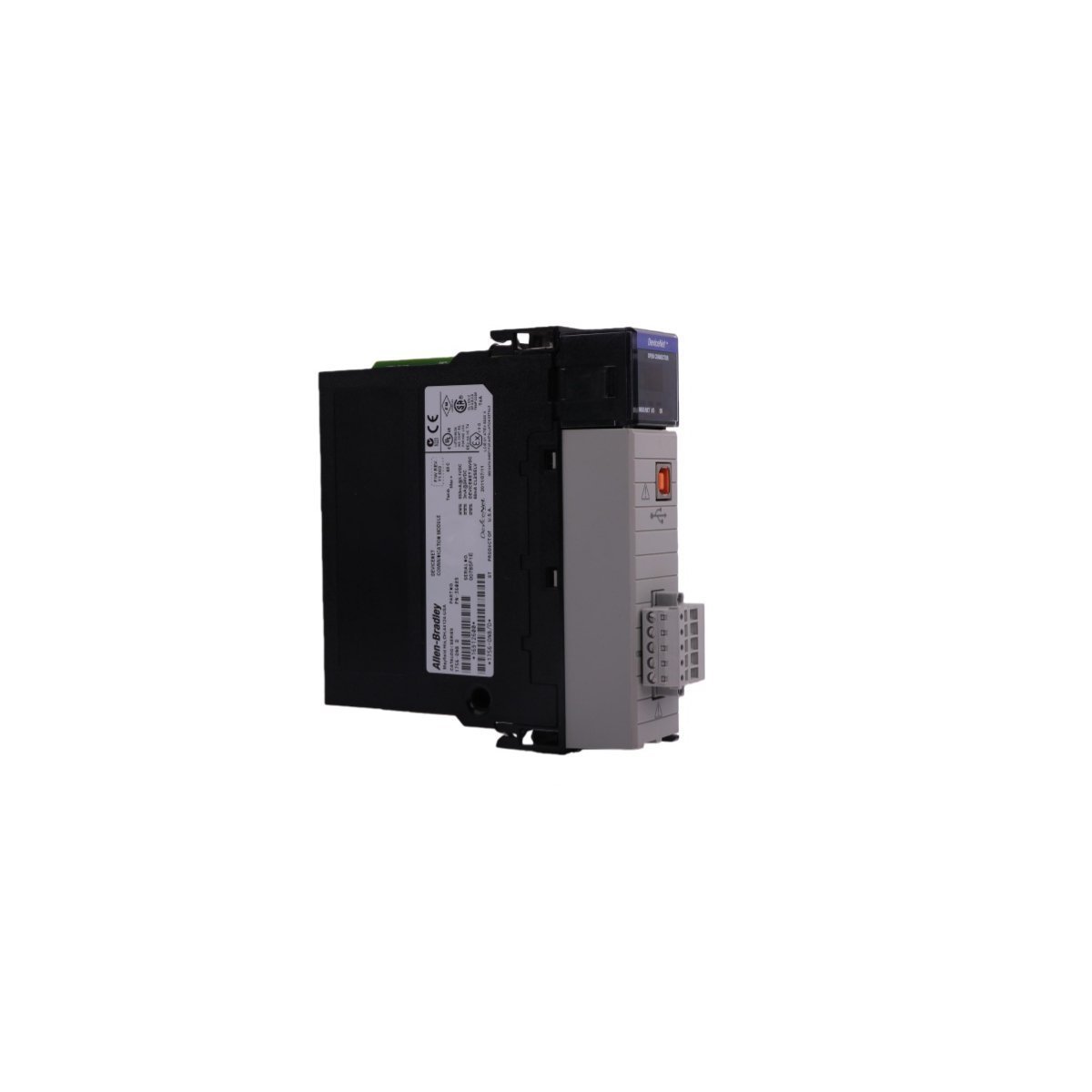
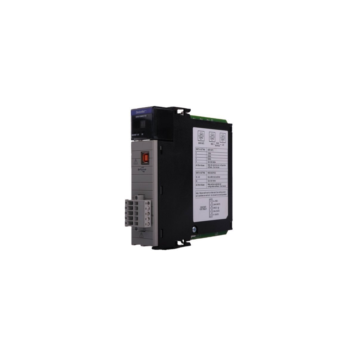
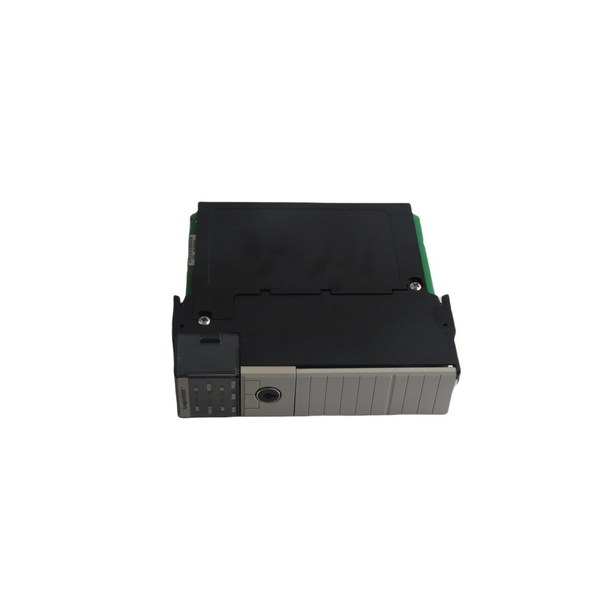
You are here:
SKU: 1756-OB16E

Allen-Bradley 1756-OB16E ControlLogix Discrete Output Module

Get the genuine Allen-Bradley 1756-OB16E ControlLogix Discrete Output Module featuring 16 electronically fused points and 24 VDC sourcing outputs. Discontinued Spare, Original Surplus with Global Shipping. Minimize automation downtime now.

The Allen-Bradley 1756-OB16E, also cataloged as the 1756-OB16E Discrete output module, operates as a dedicated hardware component for physical output signal execution within ControlLogix chassis-based platforms.

Hardware Specifications

ParameterSpecification
Model1756-OB16E
BrandAllen-Bradley
OriginUSA
Weight0.24 kg
Dimensions3.5 x 13.0 x 14.5 cm
Operating Temp0 to 60 deg C
Power Dissipation4.1 W maximum at 60 deg C
Outputs16 electronically fused (sourcing configuration)
Channel Groups2 groups of 8 channels
Operating Voltage Range10 to 31.2 VDC
Nominal Output Voltage24 VDC
Backplane Current250 mA at 5.1 VDC; 2 mA at 24 VDC
Output Current Per Point1.0 A maximum at 60 deg C
Output Current Per Module8.0 A maximum at 60 deg C
Surge Current Per Point2.0 A for 10 ms, repeatable every 2 s
Minimum Load Current3 mA per channel
Turn-On / Turn-Off Delay70 us nominal (1 ms maximum)
Continuous Isolation Voltage250 V

I/O Density Scaling and Backplane Bus Communication Velocity

The 1756-OB16E provides integrated I/O density scaling by embedding 16 independent solid-state output switches within a single slot chassis profile. This hardware communicates over a high-speed backplane bus, enabling fast real-time synchronization between the master processing unit and field components. Through the use of producer/consumer communication infrastructure, the module updates channel state confirmations and electronic fuse diagnostic bits deterministically, eliminating processing bottlenecks during simultaneous multi-channel actuation.

Frequently Asked Questions

Q: How does the electronic fusing functionality operate inside the 1756-OB16E hardware?

A: The module contains electronic protection circuits grouped across its two 8-channel structures. If a channel experiences a current overload or dead short that exceeds the threshold limits, the module trips the internal electronic fuse for that specific group, illuminates the corresponding fault LED, and transmits a diagnostic fault state packet across the backplane bus.

Q: What is the reset procedure after an electronic fuse trips on a channel group?

A: Once the external short-circuit condition or overload is cleared, the electronic fuse must be reset via the control software (such as Studio 5000 Logix Designer) by toggling the fuse reset bit or cycling the field-side 24 VDC power loop connected to that group.

Q: Can the 1756-OB16E module be inserted or removed from the chassis while power is applied?

A: Yes, the module supports Removal and Insertion Under Power (RIUP). It can be hot-swapped within the chassis while the backplane is energized, provided the field wiring terminal block is disconnected or the field loop power is completely locked out to mitigate inductive electrical arcing.


Field Installation Guidelines

  • Chassis Alignment and Mechanical Seating: Insert the module into the designated slot of the 1756 ControlLogix chassis by aligning the circuit card with the plastic guide rails. Press firmly until the physical interlocking top and bottom clips engage with the metal chassis lip.
  • Removable Terminal Block (RTB) Connection: Utilize a 1756-TBNH or 1756-TBSH terminal block for field wiring. Wire the actuators using copper conductors rated for at least 75 deg C, ensuring the terminal screws are torqued to the manufacturer manual specification.
  • Field Power Routing: Connect independent external 24 VDC power supplies to the DC+ and DC- common terminals for Group 0 and Group 1. Separate these low-voltage DC lines from high-voltage AC cables by at least 150 mm to shield the output circuits from capacitive noise injection.
  • Inductive Load Suppression: When switching inductive components like mechanical solenoids, starter coils, or heavy industrial relays, place a suppression diode directly across the load terminals to contain reverse EMF voltage spikes and protect the solid-state sourcing transistors.