


Sale!
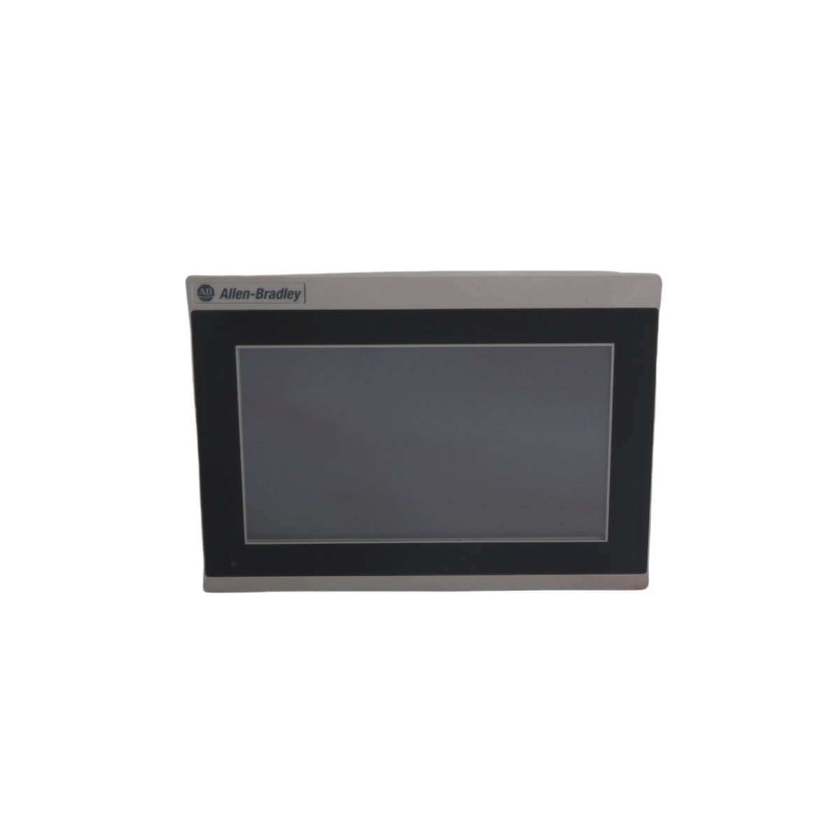
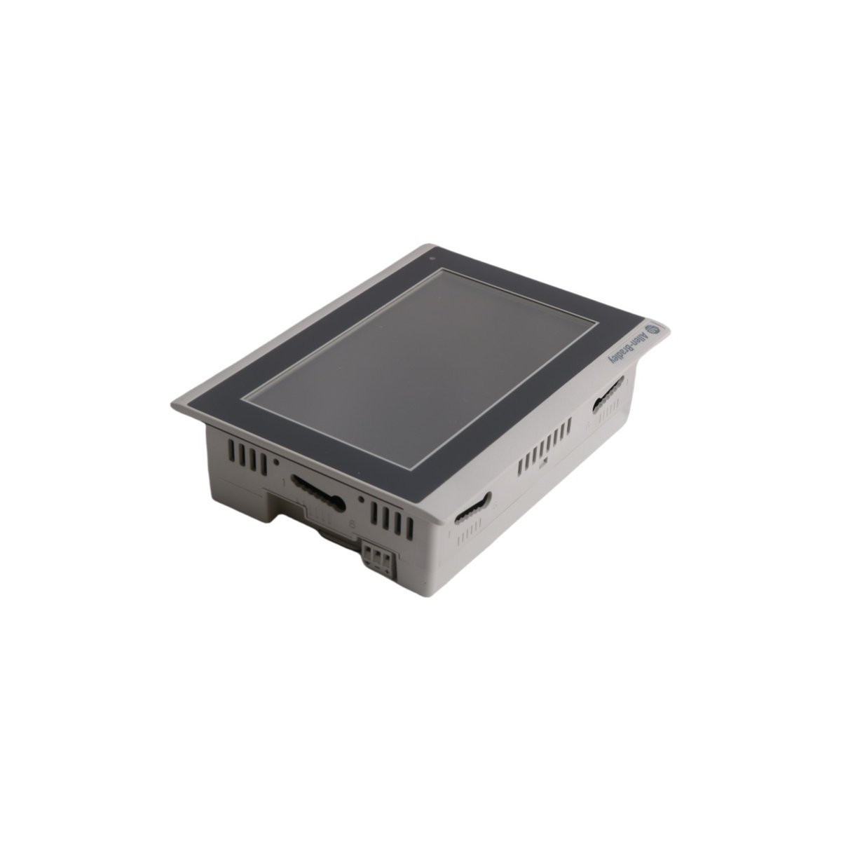
Allen-Bradley 2711R-T7T PanelView 800 Graphic Terminal
The Allen-Bradley 2711R-T7T is a 7-inch PanelView 800 HMI featuring a high-resolution touchscreen, extensive protocol support, and robust integration for industrial control systems.
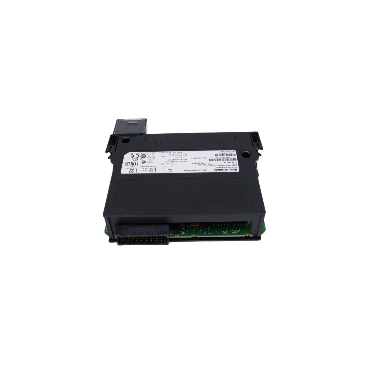
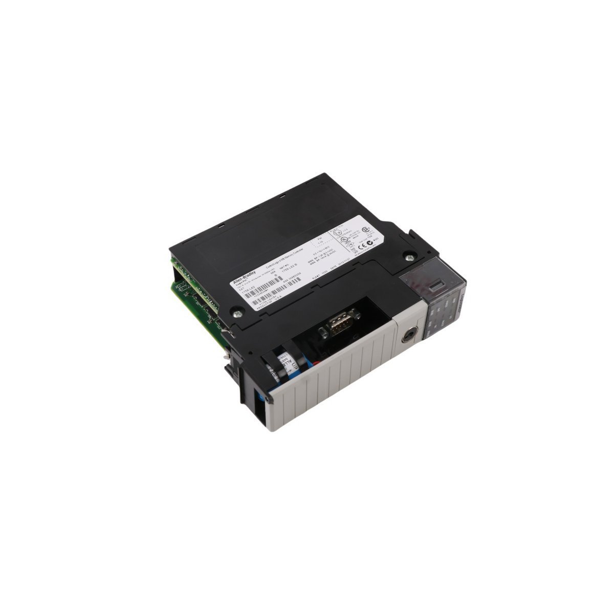
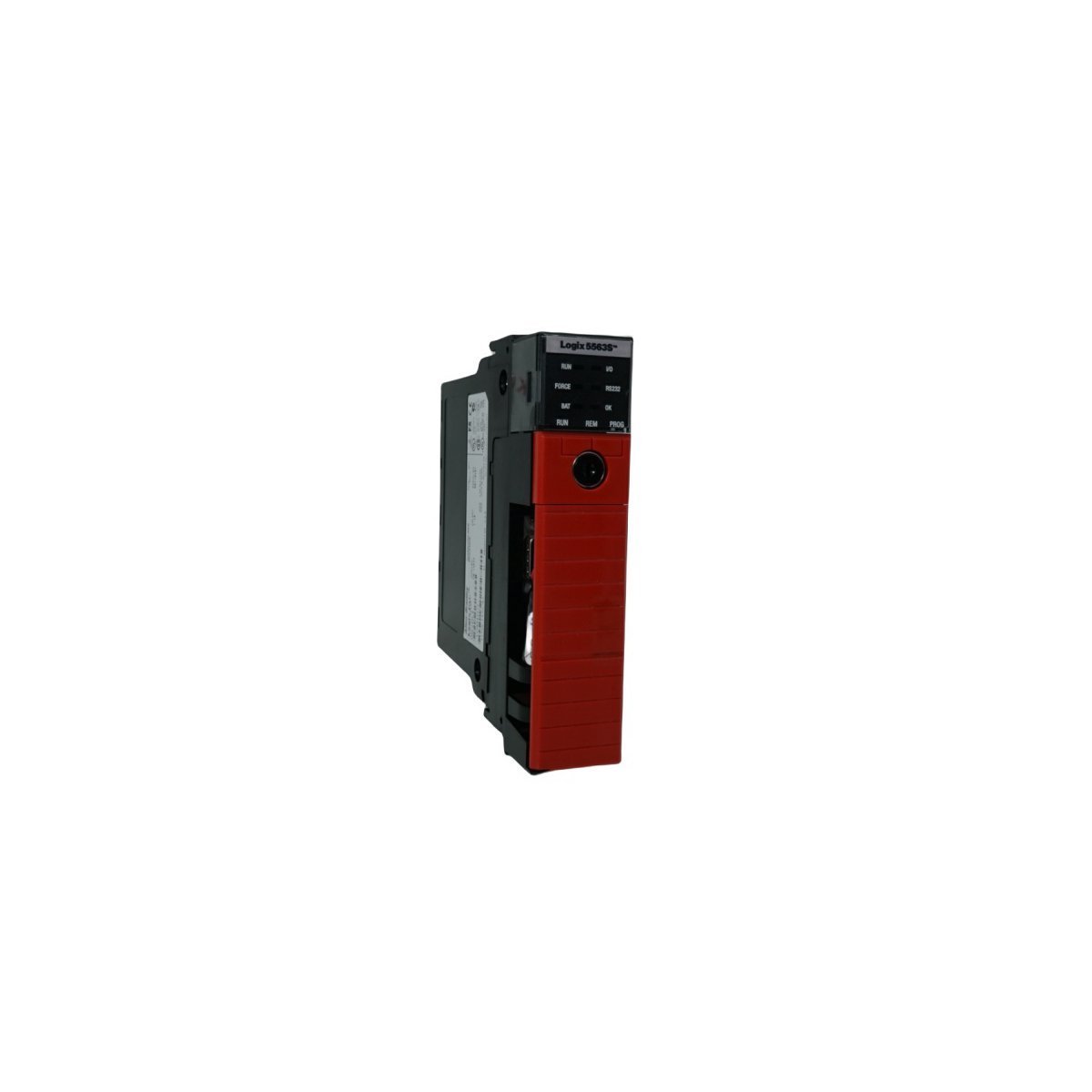
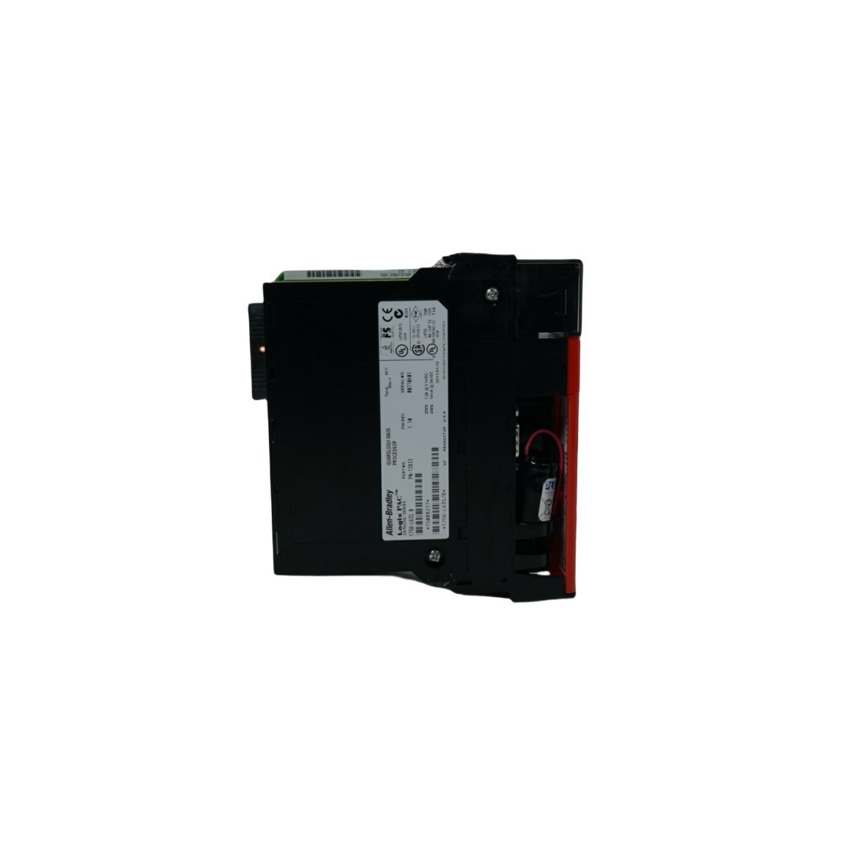
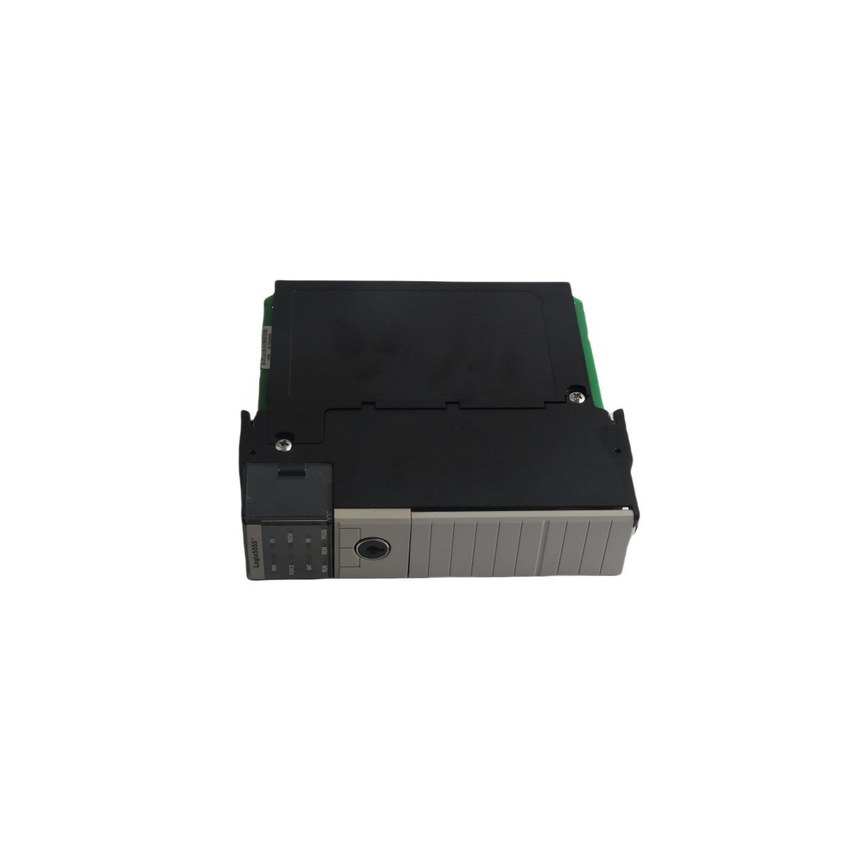
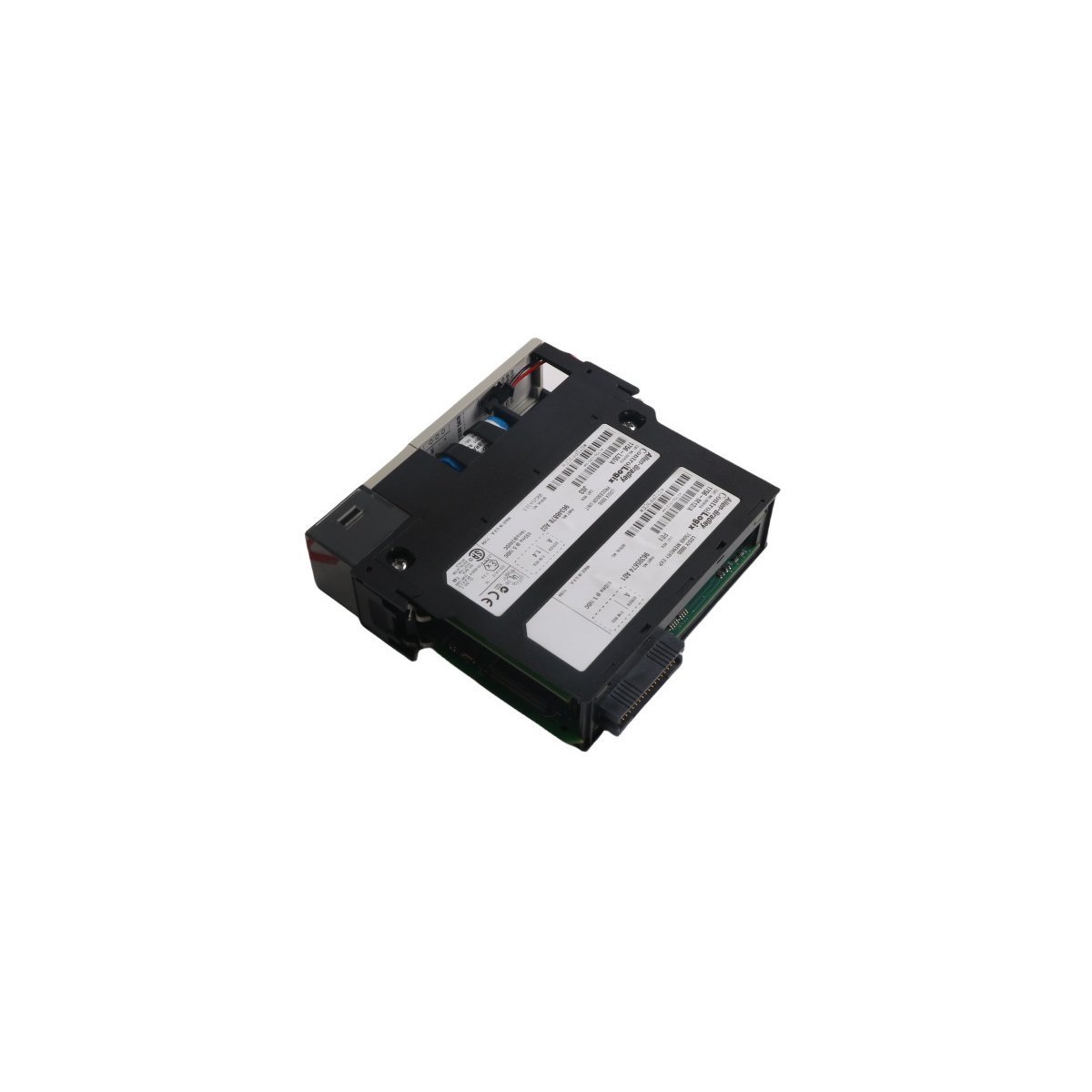
The Allen-Bradley 1756-L55M22 is a 750 KB ControlLogix Controller. Brand New, Original Stock, Global Shipping available for automated industrial platforms.
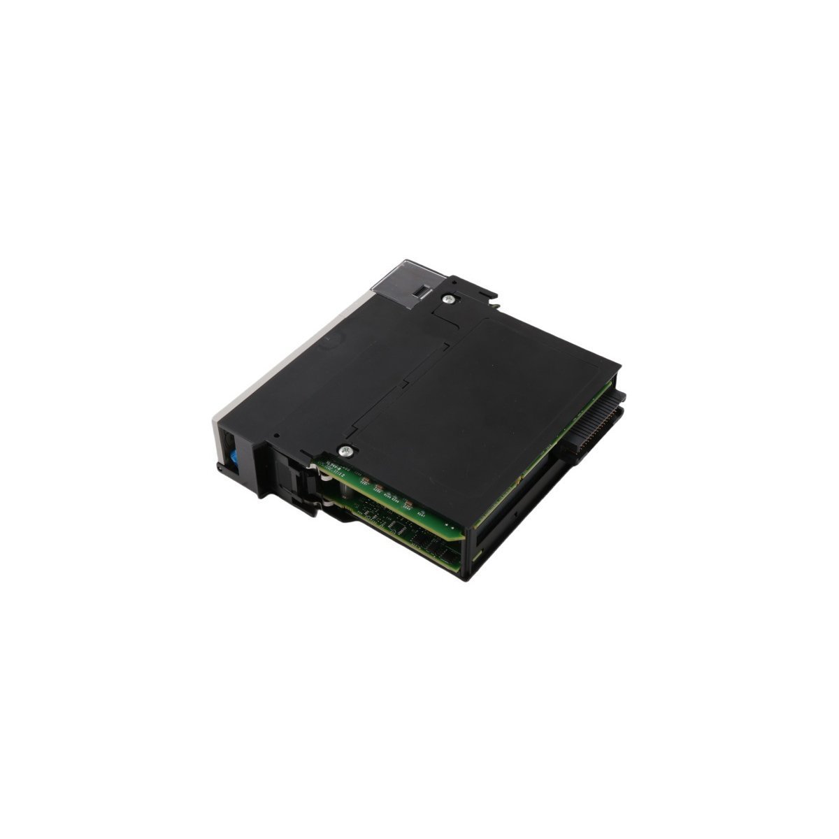
The Allen-Bradley 1756-L55M22, also cataloged as the 1756-L55M22 ControlLogix Controller, operates as a dedicated hardware component for application logic execution and backplane data exchange within ControlLogix 5555 system platforms. The unit features a dual-CPU architecture comprising a Logix processing unit for application code execution and a dedicated backplane CPU to handle I/O data communication and synchronization across the chassis.
| Parameter | Specification |
|---|---|
| Model | 1756-L55M22 |
| Brand | Allen-Bradley |
| Origin | USA |
| Weight | 0.36 kg |
| Dimensions | 14.35 x 14.0 x 14.5 cm |
| Operating Temp | 0 to 60 deg C |
| Power Consumption | 1.25 A at 5.1 VDC; 0.014 A at 24 VDC |
| User Memory (Logic/Data) | 750 KB |
| Dedicated I/O Memory | 208 KB |
| Local I/O Capacity | 250 words |
| System Platform | ControlLogix / GuardLogix |
| Comm Port | Serial RS-232 (via 1756-CP3) |
| Battery Type | 1756-BA1 / 1756-BATM |
The 1756-L55M22 implements a hardware-based multitasking architecture to prioritize backplane bus communication velocity and logic synchronization. The internal backplane processor acts independently of the main execution core, ensuring that deterministic networks like EtherNet/IP, ControlNet, and DeviceNet maintain stable request-response intervals irrespective of application code complexity. It natively supports produced/consumed tag allocation, enforcing strict update times across distributed network nodes via continuous backplane data scanning. Firmware flash compatibility determines the maximum instruction set capability, requiring alignment between the controller hardware revision and the RSLogix 5000 programming environment.
Q: How does the dual-CPU architecture impact the local backplane execution time?
A: The main Logix CPU processes the application program tasks sequentially, while the secondary backplane CPU handles communication cycles and diagnostic polling. This separation isolates user program execution from variable network communication loads, preventing interruptions in routine execution times.
Q: What is the behavior of the onboard diagnostic indicators during an active I/O fault?
A: The controller features a front-panel I/O LED indicator. An active fault or communication loss with designated I/O modules causes the green I/O LED to flash, prompting the execution of the system fault handler to capture diagnostics.
Q: What are the backup runtime restrictions during power deprivation cycles?
A: Non-volatile data retention is dependent on the external battery assembly (1756-BA1 or 1756-BATM). Without operational battery power, volatile RAM memory containing the logic application and runtime tags will clear upon a complete loss of chassis backplane power.
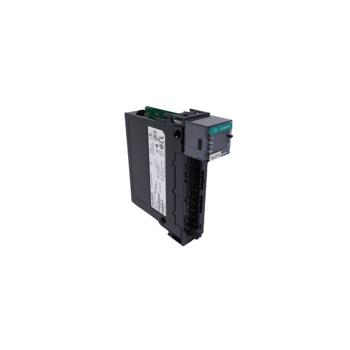
The Allen-Bradley ControlLogix 1756-L55M16 is an advanced industrial controller from the Logix5000 family, equipped with 7.5 MB of user logic memory, 208 KB of dedicated I/O memory, and a dual-CPU processor architecture that optimizes logic execution separate from chassis backplane traffic. Built for heavy-duty automation systems, it manages up to 128,000 total digital I/O points with a blistering 0.08 ms program scan time. Supporting multi-network connectivity across EtherNet/IP, ControlNet, and DeviceNet alongside producer/consumer data tag broadcasting, this processor provides the ultimate scalability, multi-language scheduling, and reliable multitasking control for complex, modern factory floor operations.


We are committed to protecting your privacy. The information collected here is strictly used to provide the requested quotes, technical support, and relevant industrial automation solutions.