Sale!
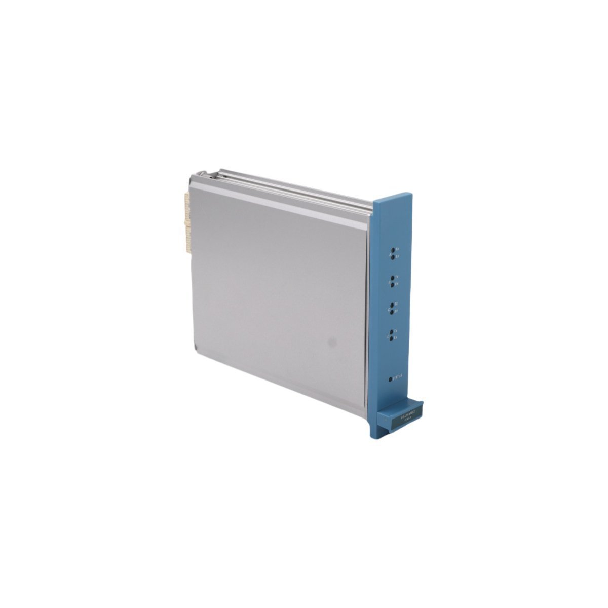
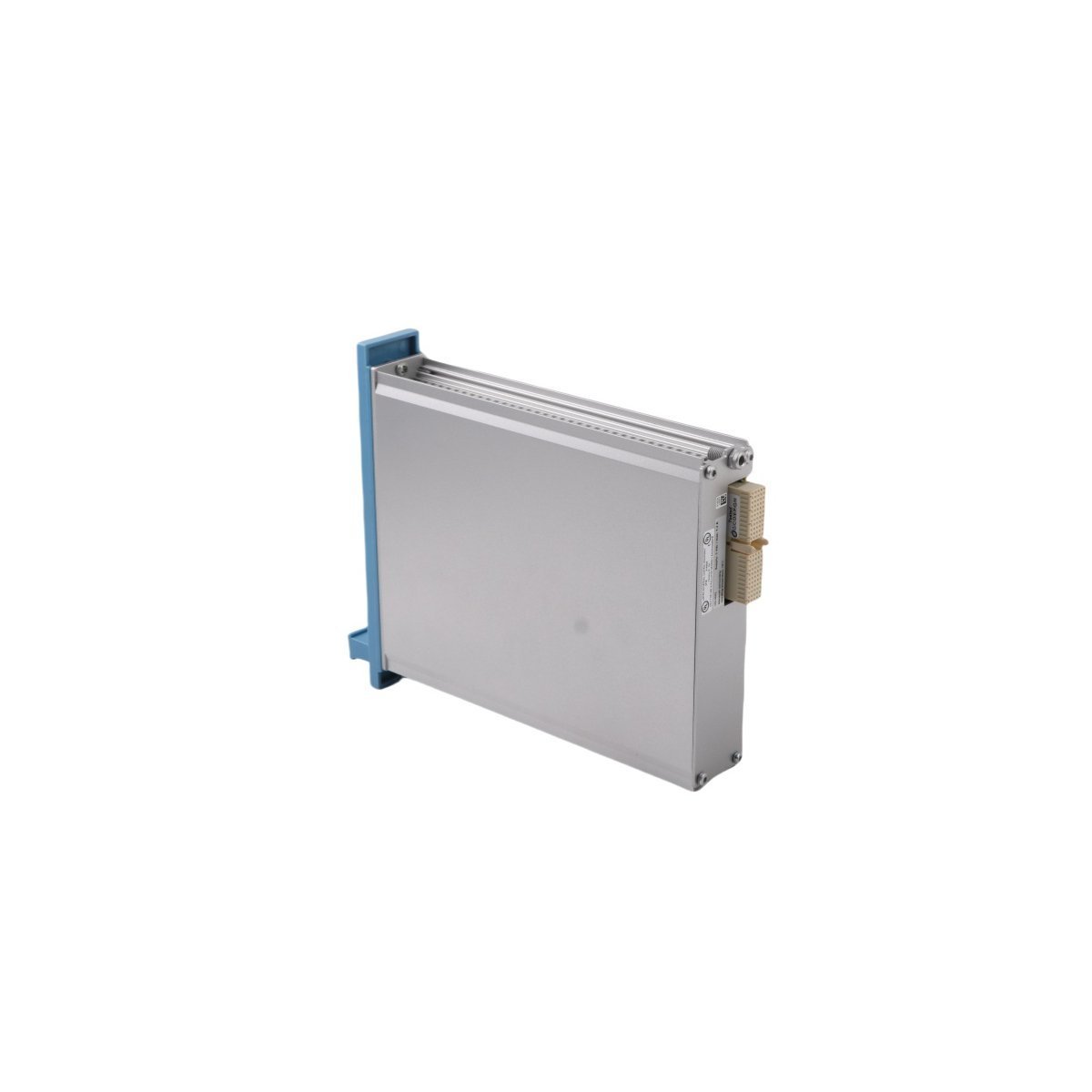
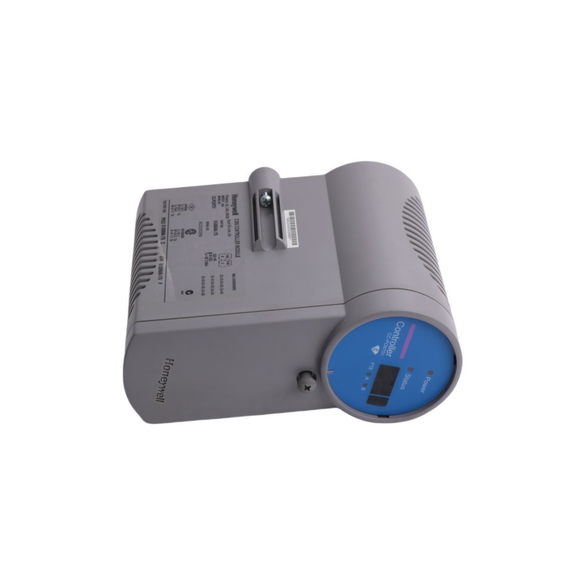
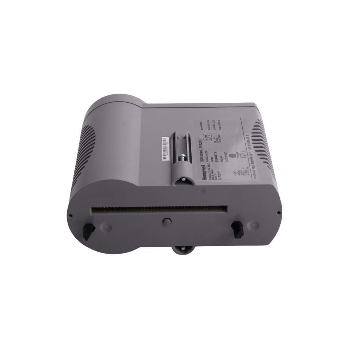
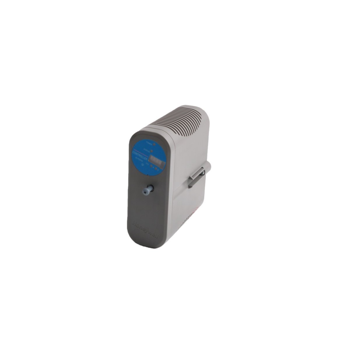
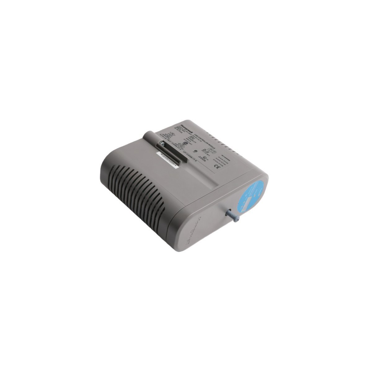
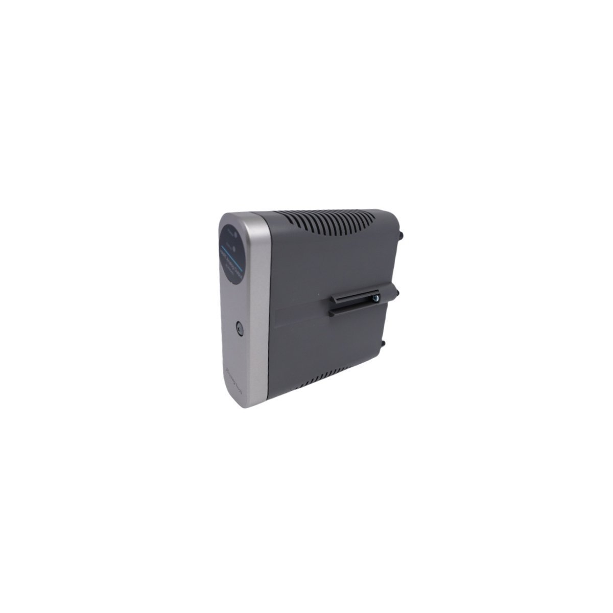
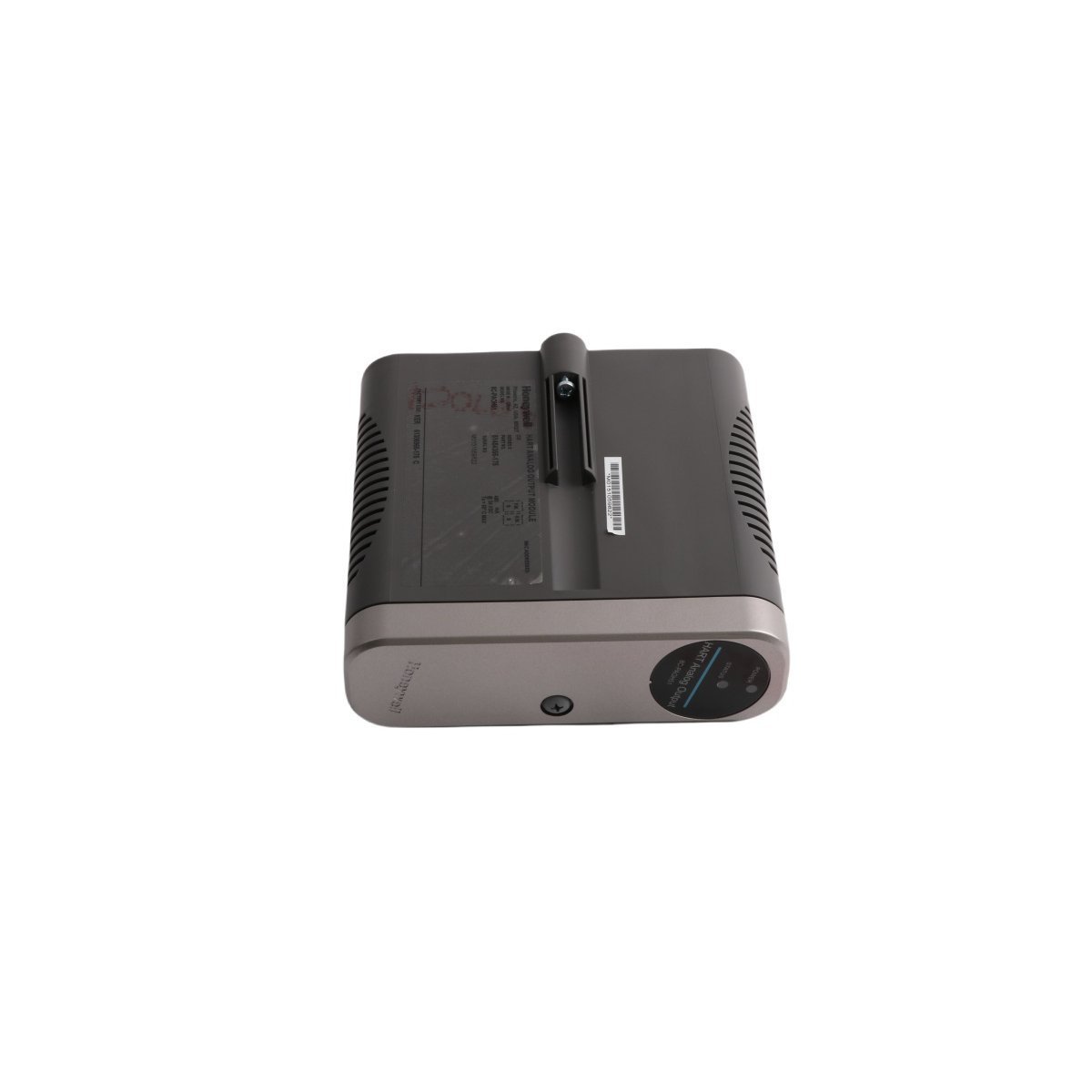
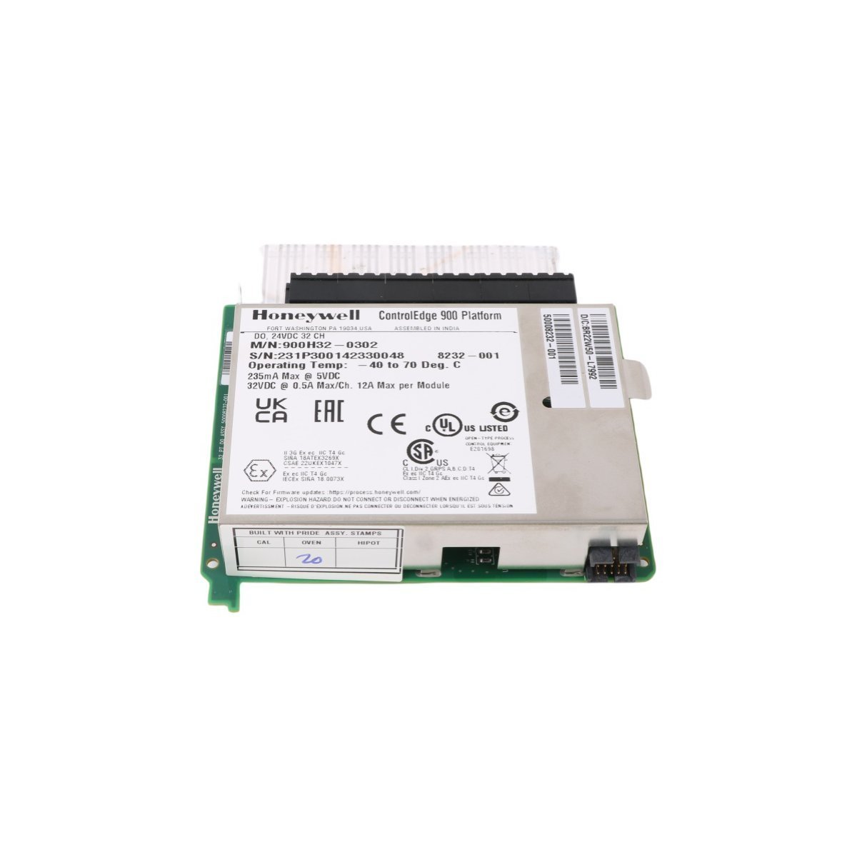
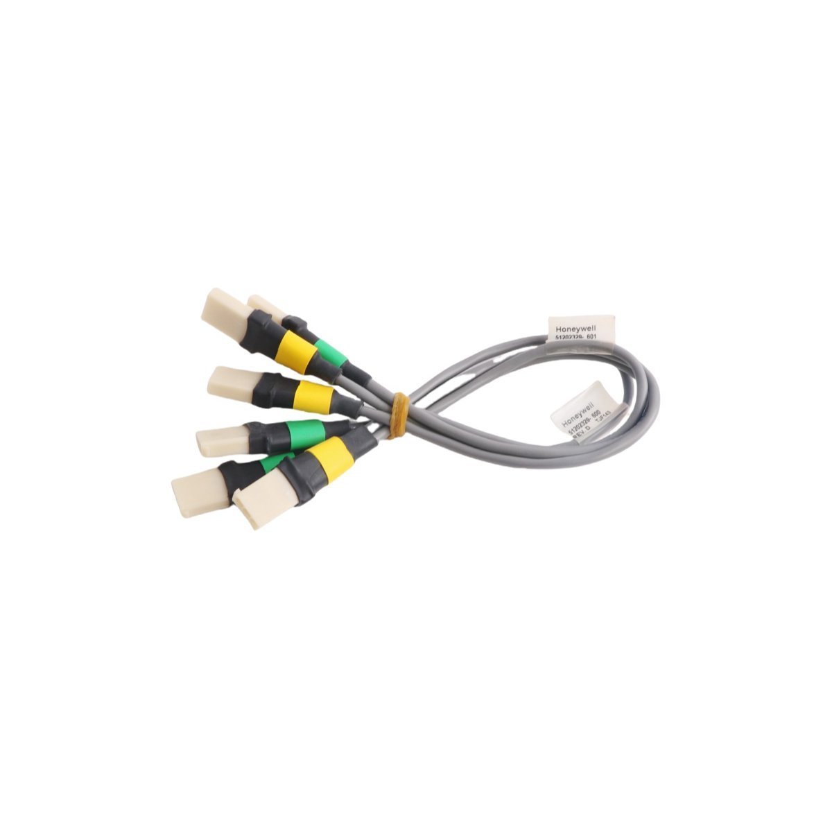
Honeywell FE-USI-0002 Universal Safety Interface
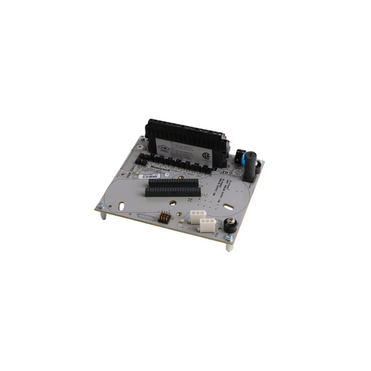
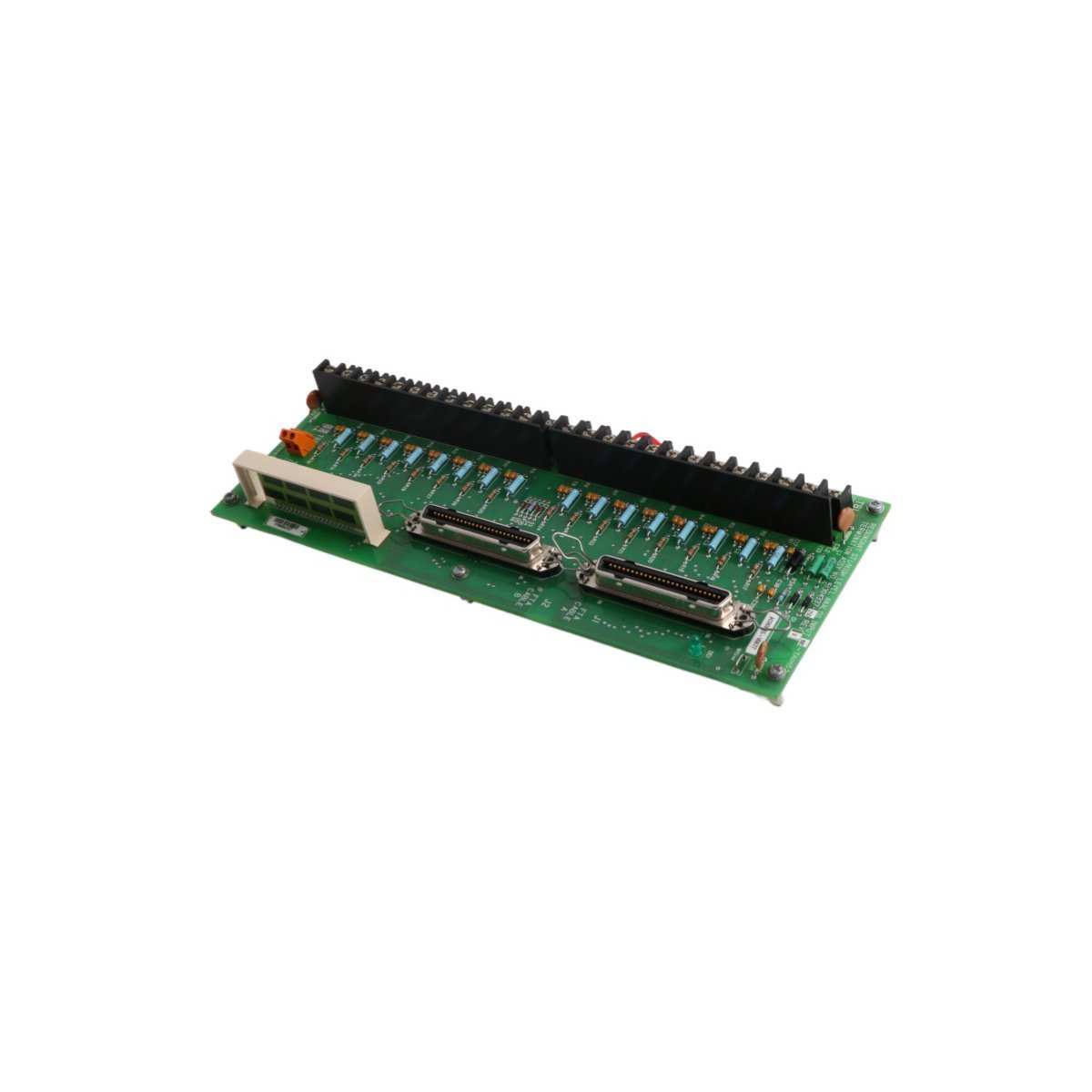
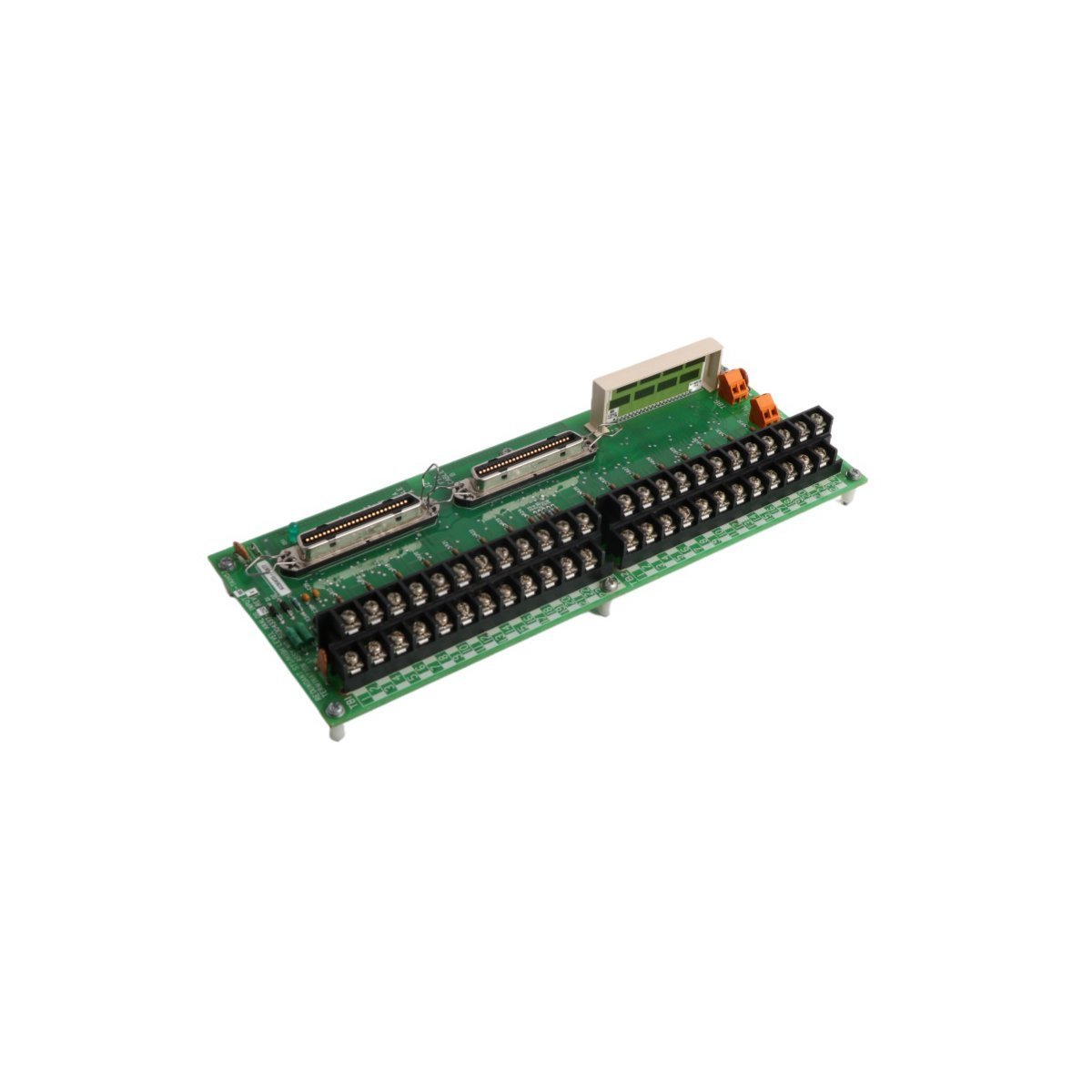
Configured for signal routing and communication bridging within Experion PKS platforms, the Honeywell FE-USI-0002 (FE-USI-0002 Universal Safety Interface) provides direct physical/electrical execution.
Hardware Specifications
| Parameter | Specification |
|---|---|
| Model | FE-USI-0002 |
| Brand | Honeywell |
| Origin | USA |
| Weight | 0.68 kg |
| Dimensions | 3.5 x 22.7 x 17.5 cm |
| Operating Temp | -40 deg C to 70 deg C (Standard industrial range) |
| Power Consumption | 5.2 W nominal |
| Module Type | Universal Safety Interface |
| Range of Product | Experion PKS |
| System | DCS |
| Communication Service | Ethernet router |
| Status | Active |
Architectural Integration and HART Loop Protocol
The module implements standard 4-20 mA HART loop protocol capabilities for analog instrumentation integration, paired with robust channel-to-channel isolation architecture to mitigate common-mode interference in high-voltage industrial enclosures. Cold junction compensation (CJC) circuits are embedded to maintain precision for connected thermocouple loops, while dual-port Ethernet routing guarantees deterministic packet delivery across distributed controller nodes.Frequently Asked Questions
Q: What is the backplane current consumption limit when mounting multiple FE-USI-0002 units in a single I/O chassis?A: Each module draws a regulated current load from the system power bus; total slot population must not exceed the maximum amperage output specified for the local power supply module.Q: Does the module support online hot-swapping during active process operations?A: Yes, active backplane design permits physical replacement under power, provided that redundant communication paths and fail-safe state execution are verified prior to card extraction.Field Installation Guidelines
- Mount the unit vertically on a standard 35 mm DIN rail to maintain convection cooling profiles across the housing vents.
- Ensure all shield drain wires from field cables are terminated directly to the designated earth grounding bar to prevent electromagnetic coupling.
- Maintain a minimum clearance of 50 mm above and below the module enclosure to allow adequate thermal dissipation within the marshalling cabinet.