Sale!
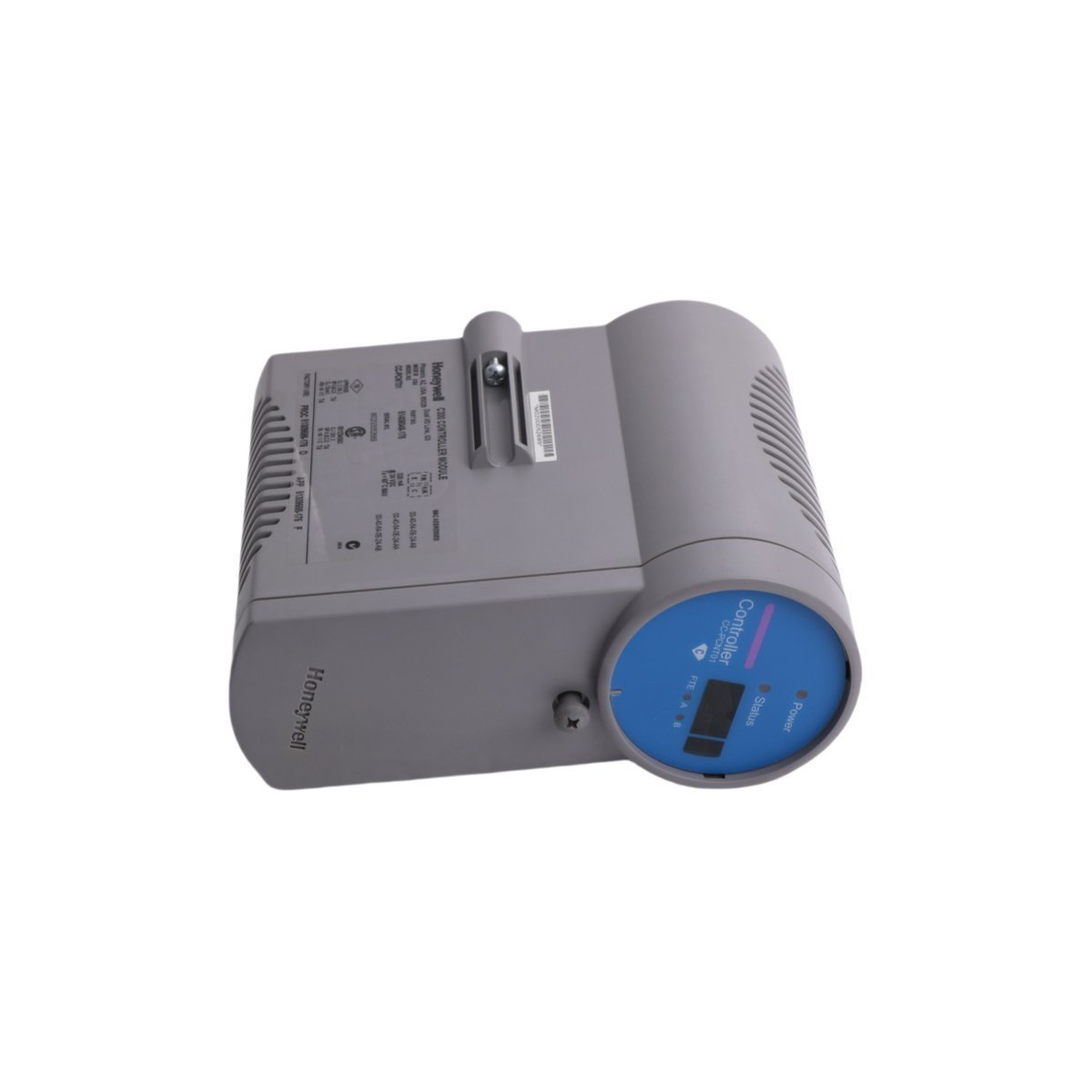
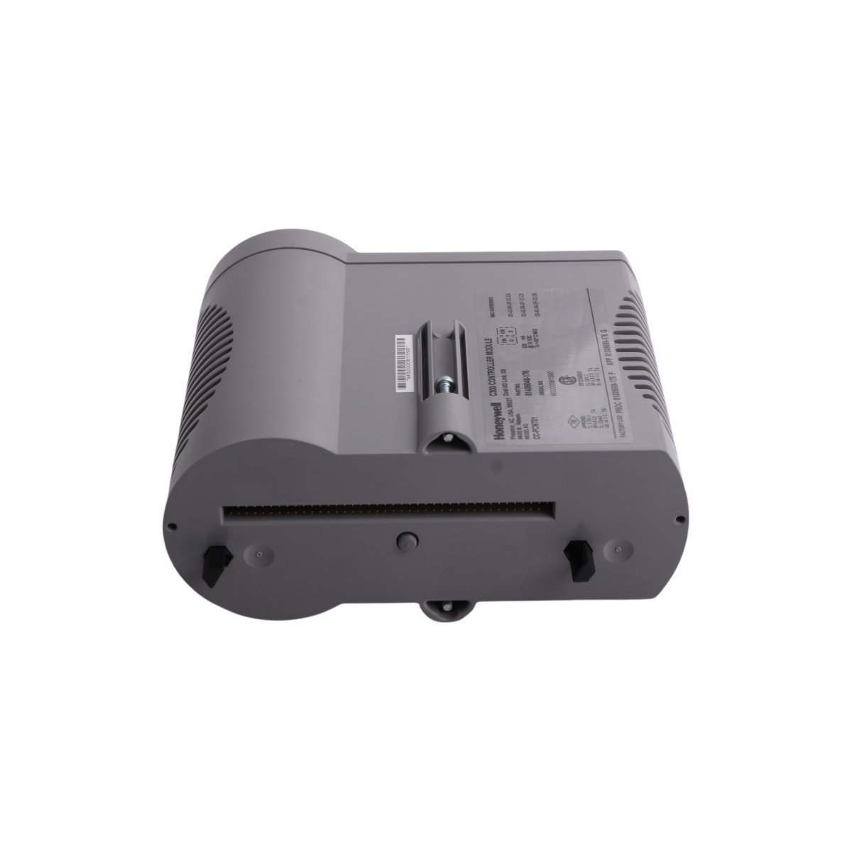
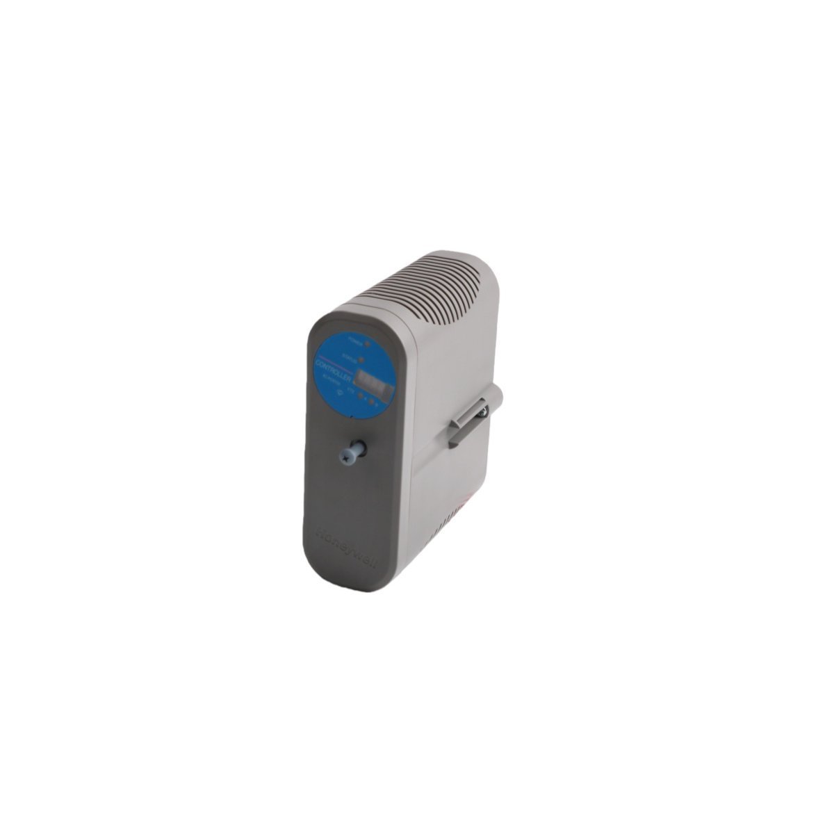
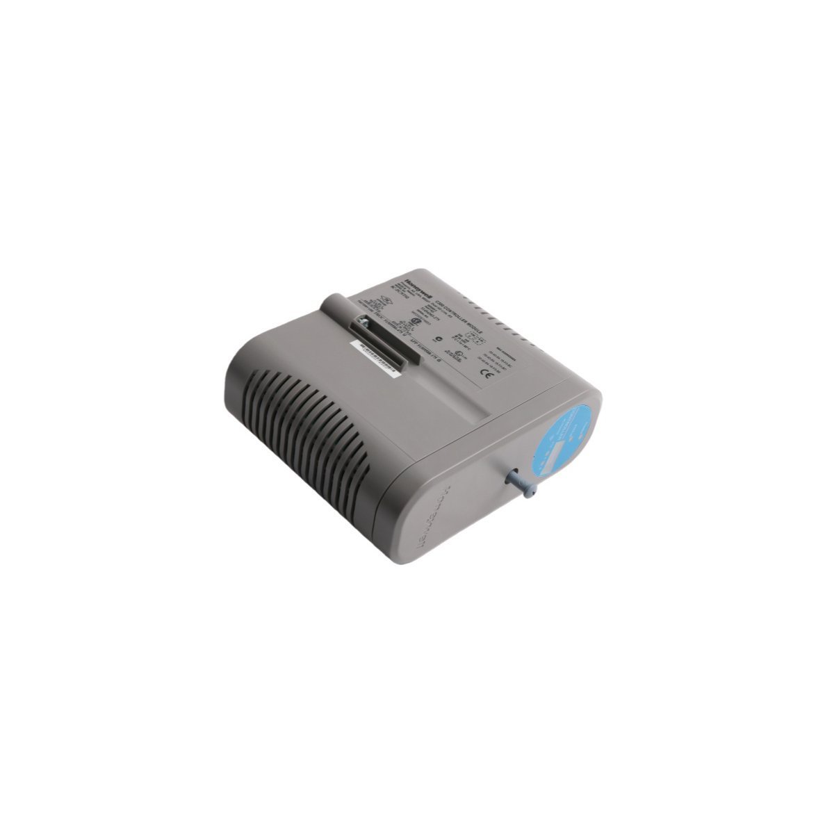
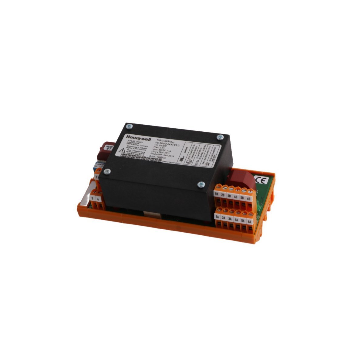
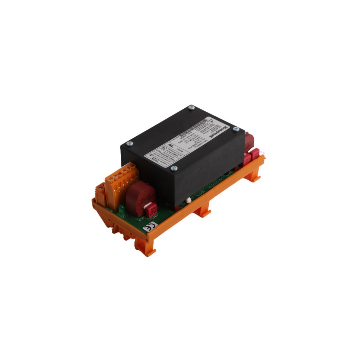
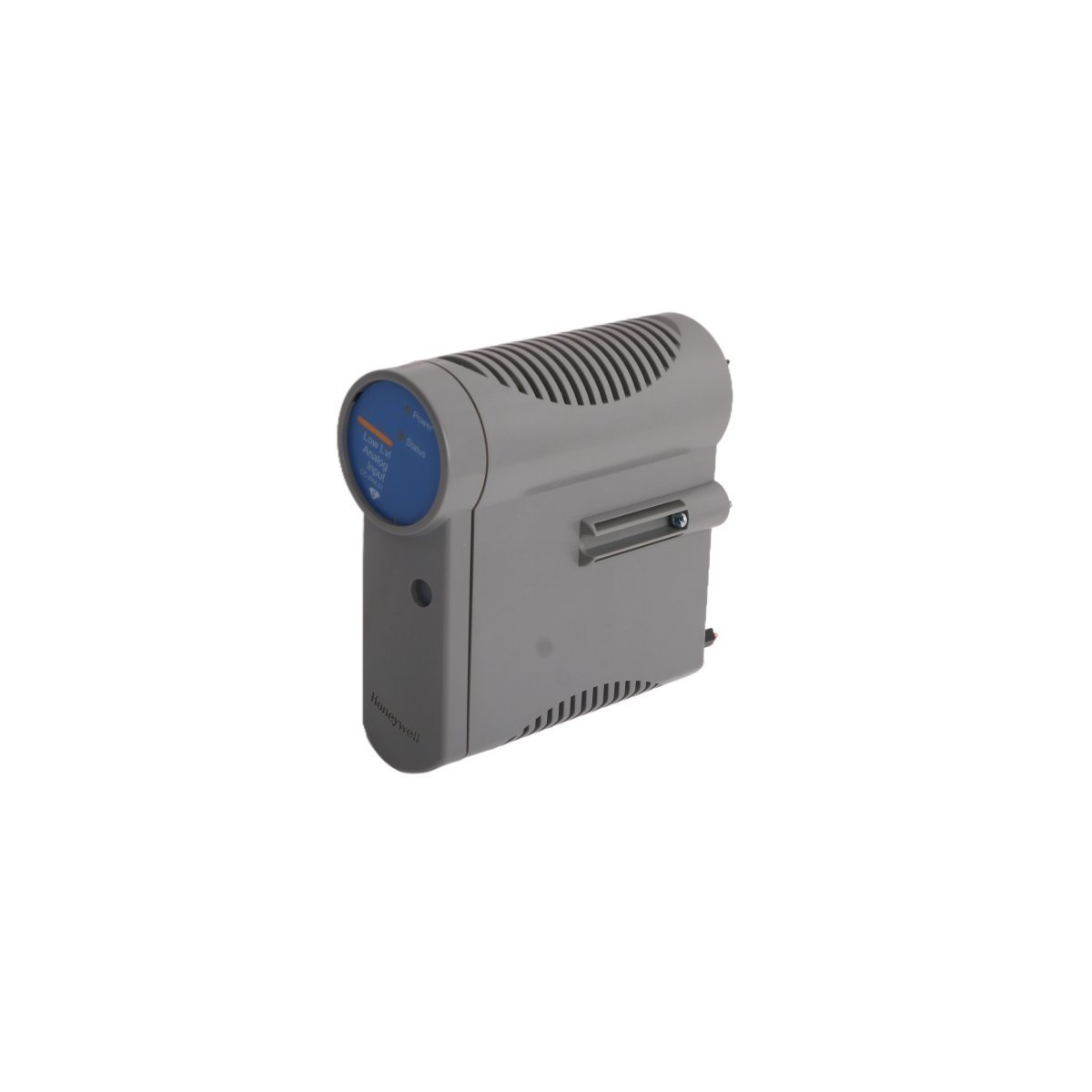
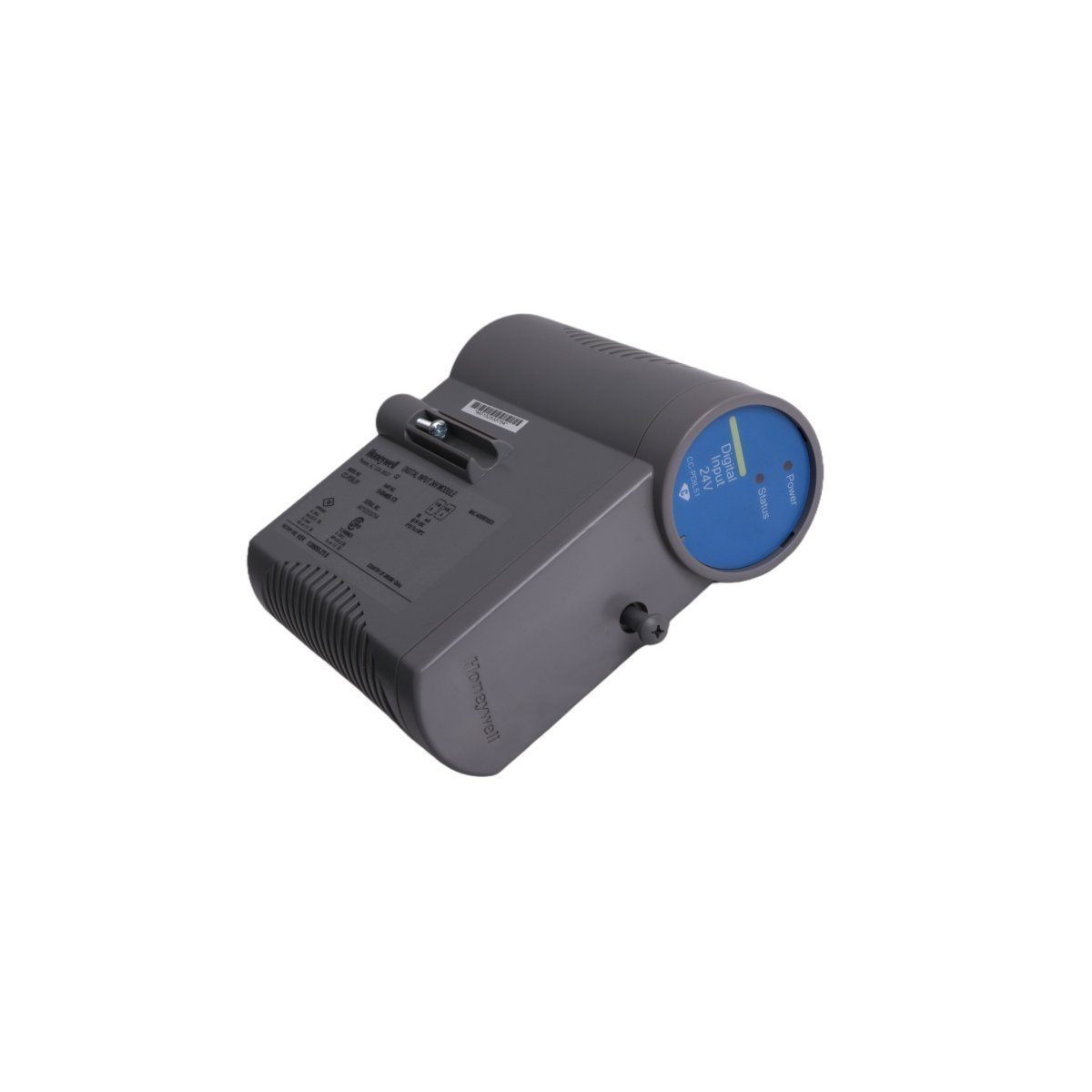
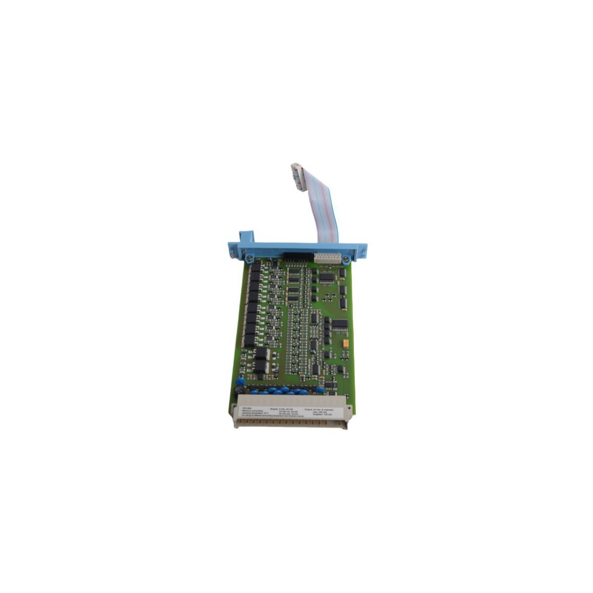
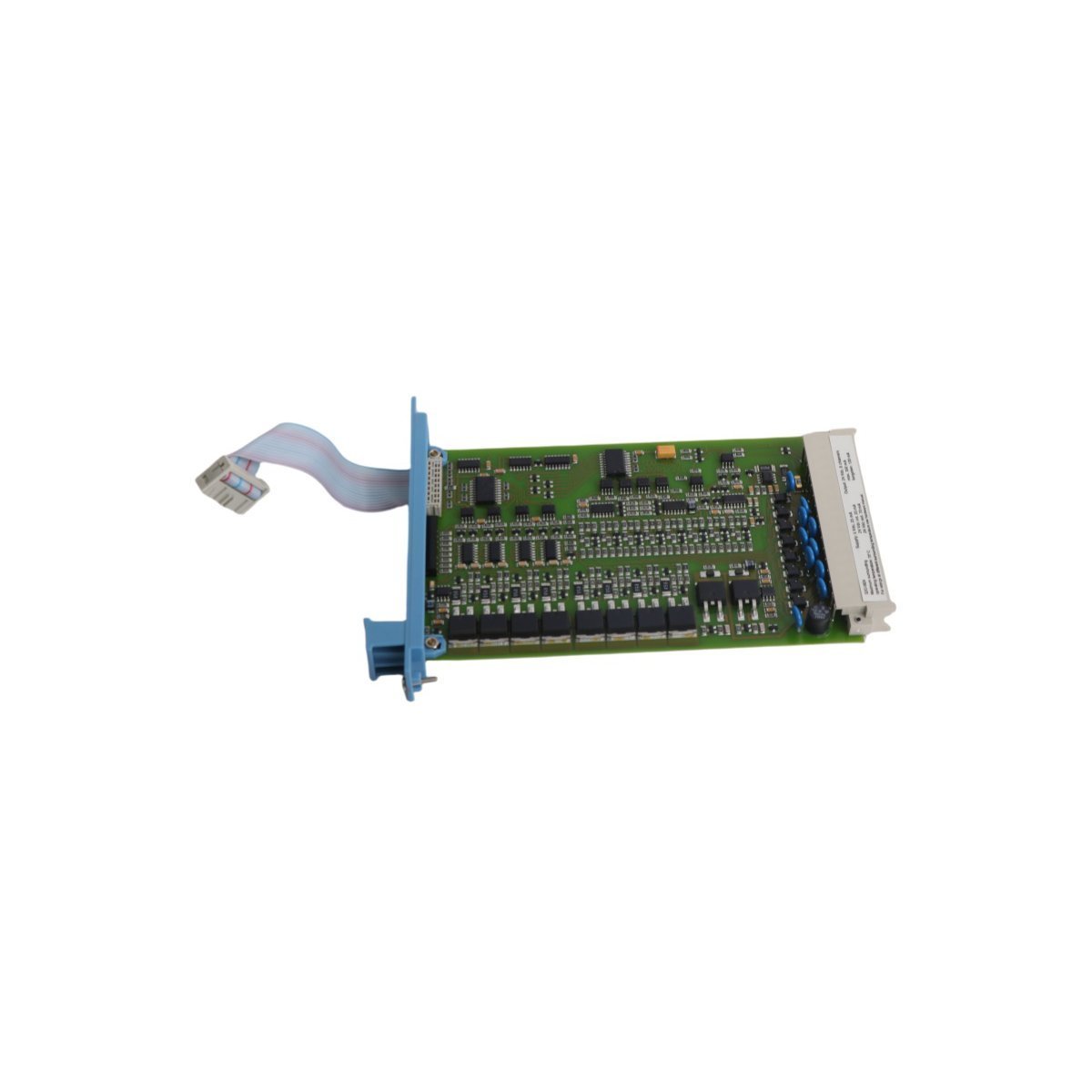
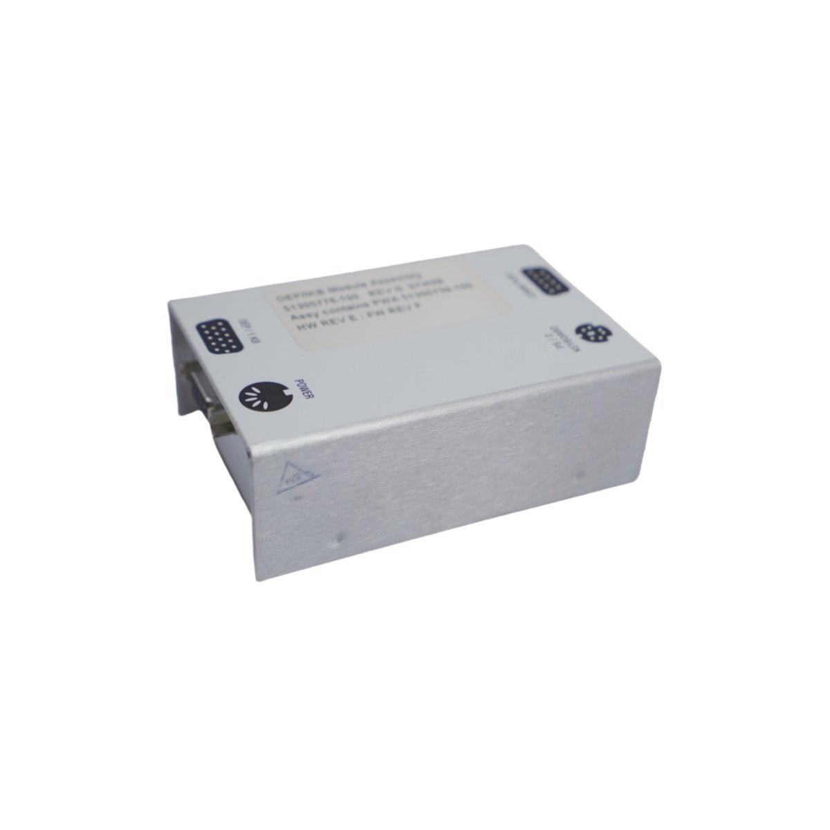
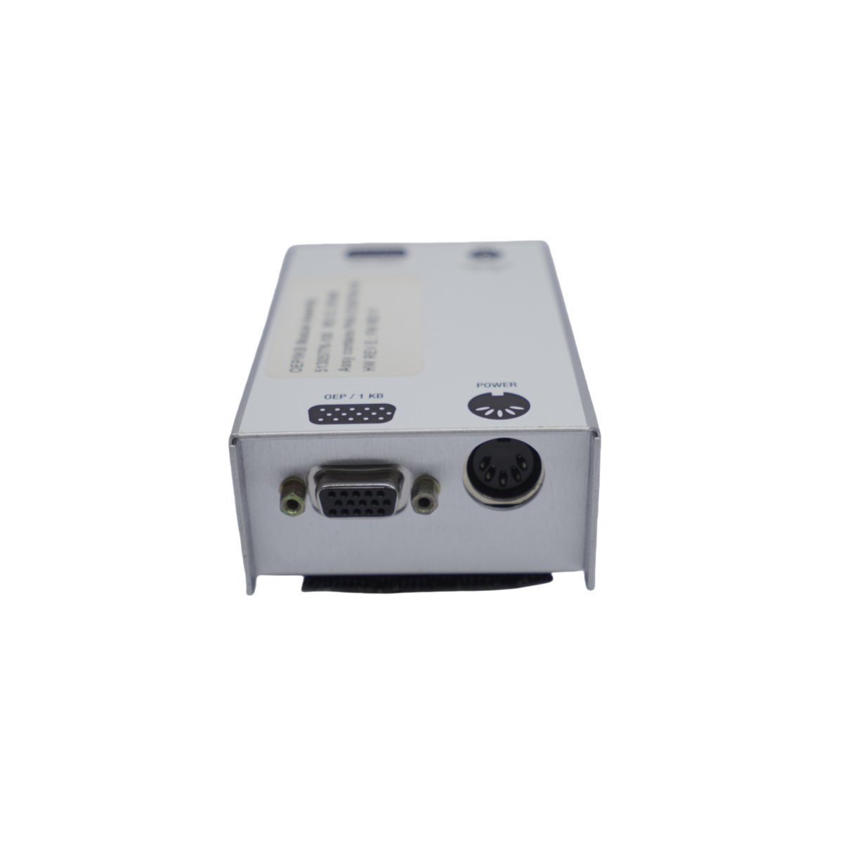
Honeywell 51109693-100B Bracket
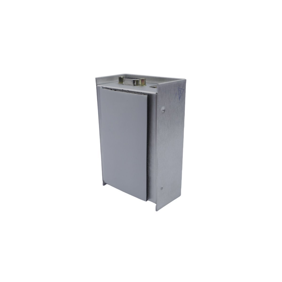
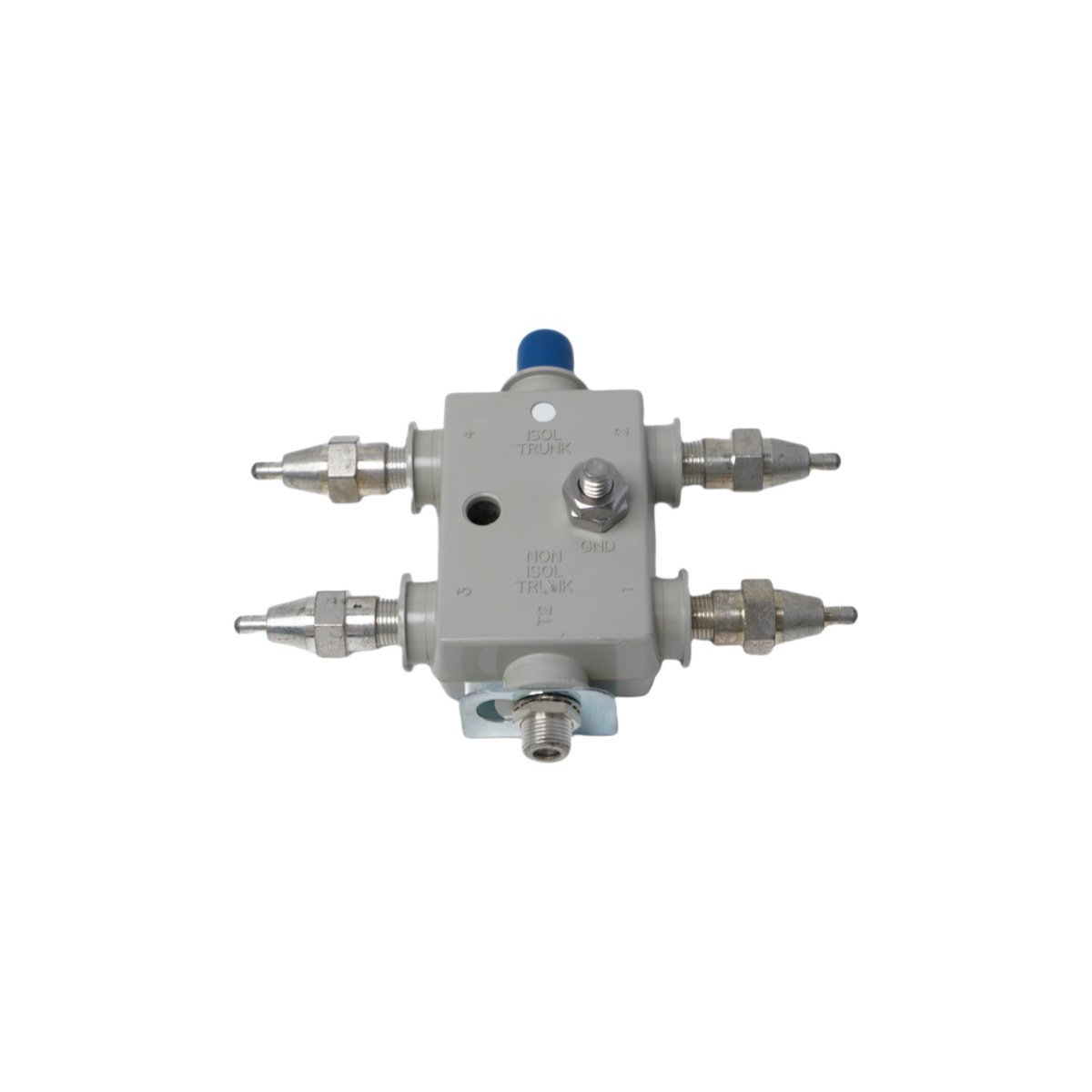
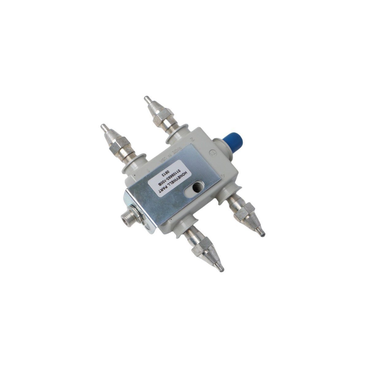
The Honeywell 51109693-100B, also cataloged as the 51109693-100B Bracket, operates as a dedicated hardware component for mechanical chassis mounting and structural module retention within Experion PKS platforms.
Hardware Specifications
| Parameter | Specification |
|---|---|
| Model | 51109693-100B |
| Brand | Honeywell |
| Origin | USA |
| Weight | 0.22 kg |
| Dimensions | 12 x 9.8 x 4 cm |
| Operating Temp | -40 deg C to 70 deg C |
| Power Consumption | Passive mechanical component (0 W) |
| Module Type | Bracket |
| Range of Product | Experion PKS |
| System | DCS |
| Communication Service | Ethernet router |
| Status | Active |
Architectural Integration and Signal Loop Isolation
The assembly integrates into distributed control infrastructure via standard panel mounting interfaces, maintaining mechanical stability for associated processing nodes. The physical design incorporates grounding provisions and corrosion-resistant metallic alloys to withstand harsh industrial atmospheres. Furthermore, channel-to-channel isolation and cold junction compensation (CJC) alignment structures are safeguarded within the mounting perimeter to prevent electromagnetic interference from compromising adjacent analog and digital signal loops.Frequently Asked Questions
Q: What are the torque limits for securing the mounting bolts on the bracket frame?A: Fasteners must be torqued to manufacturer-specified limits using calibrated tools to prevent deformation of the structural chassis.Q: Does the bracket maintain electrical continuity for system grounding?A: Yes, metallic contact points are engineered to establish low-impedance paths to the enclosure ground bus, mitigating common-mode noise.Field Installation Guidelines
- Mount the bracket securely to a flat, vibration-damped vertical surface using appropriate industrial-grade hardware.
- Ensure all protective earth bonding connections are established prior to energizing the installed electronic modules.
- Maintain adequate physical clearance around the unit to facilitate thermal dissipation and subsequent maintenance access.