


Sale!
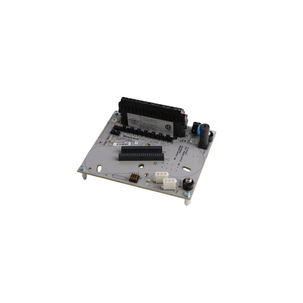
Honeywell CC-TAOX01 Analog Output Module
Honeywell CC-TAOX01 Analog Output Module. Brand New, Original Stock. Global Shipping. 16-channel C300 DCS module with HART support. Order now.
Purchase the genuine HONEYWELL 51153818-203 Jumper Kit. Features a premium gray multi-wire configuration with a 2.54 mm pitch for secure DCS backplane bridging. Available in Brand New condition with fast worldwide shipping.
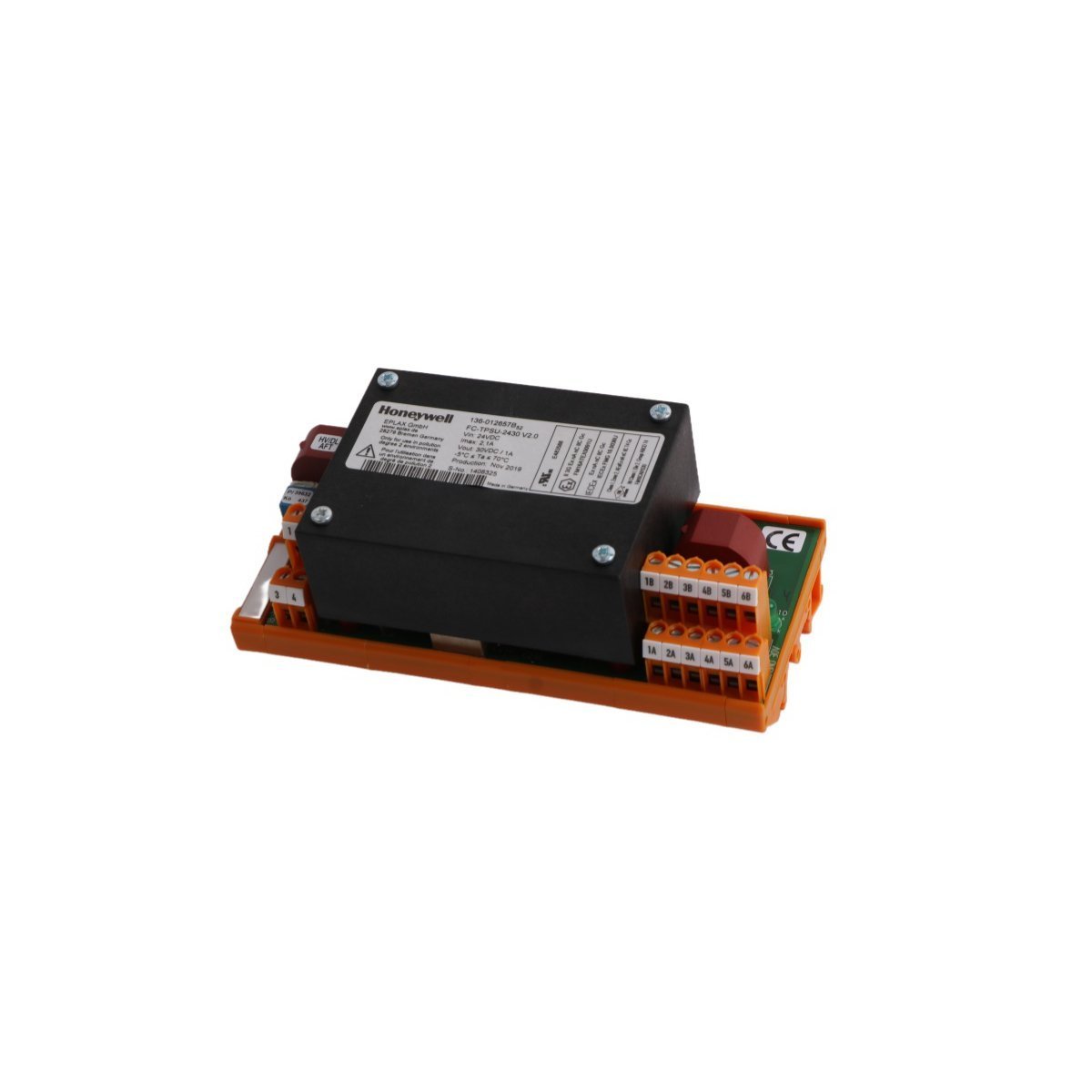
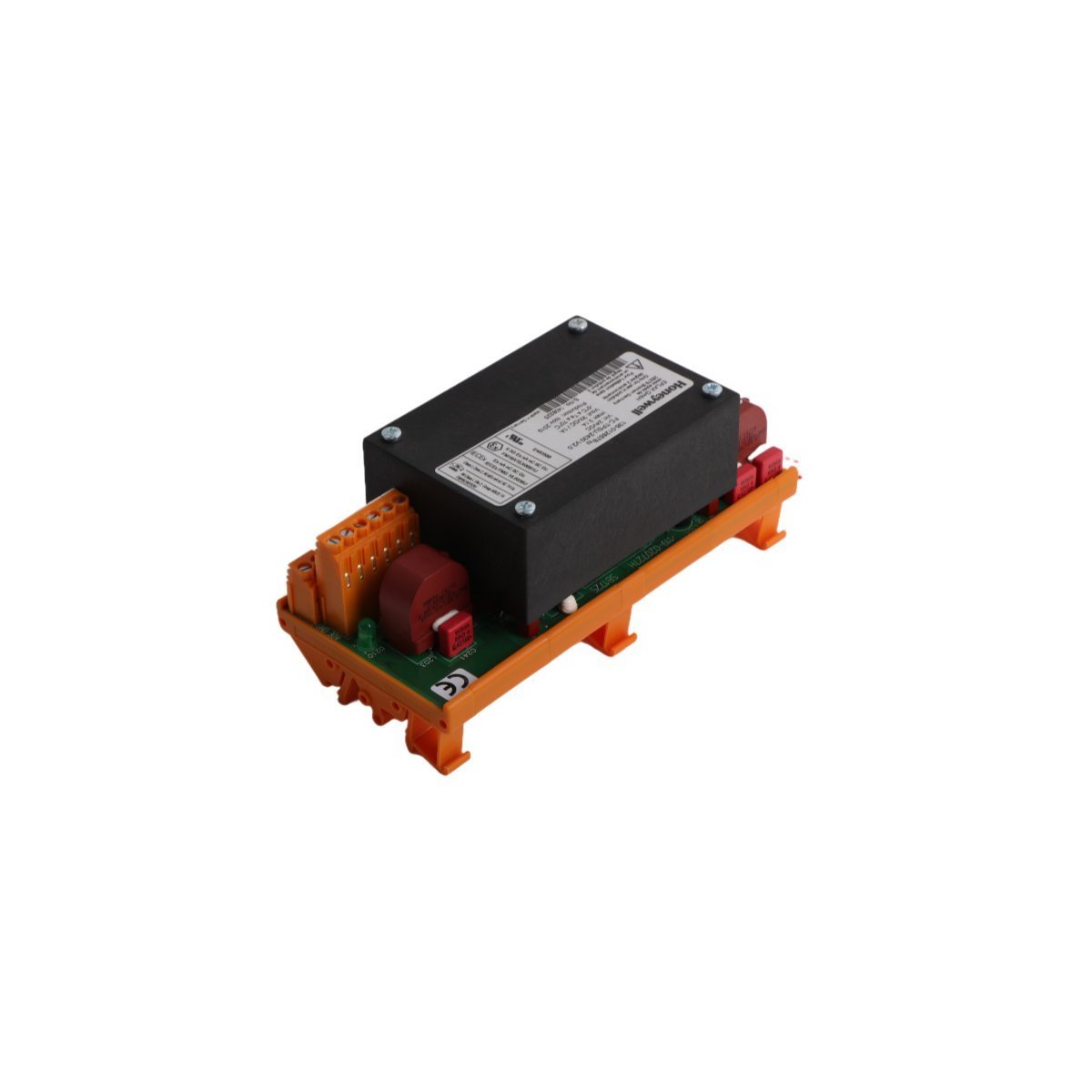
The HONEYWELL 51153818-203 is a specialized, multi-wire Jumper Kit (Gray Jumpers) engineered to establish rigid electrical bus connections across backplane assemblies, termination blocks, and control hardware within Honeywell Distributed Control Systems (DCS). It provides structural interconnects for signals routed through the Experion PKS and legacy TotalPlant Solution (TPS) platforms.
| Parameter | Specification |
|---|---|
| Model Number | 51153818-203 |
| Manufacturer | HONEYWELL |
| Range of Product | Experion PKS / TPS |
| Component Type | Jumper Kit Assembly (Gray) |
| Origin | USA |
| Weight | 0.4 kg |
| Dimensions | 7 x 14 x 14.5 cm (Packaged) |
| Wire Count Configuration | 21 to 30 inline wire jumpers |
| Pin/Terminal Pitch | 2.54 mm (0.100 in) standard spacing |
| Primary Application | I/O module to backplane termination jumping |
| System Classification | DCS / PLC Structural Component |
The 51153818-203 hardware pack features pre-measured, factory-insulated wire configurations mounted on unified header strips with a standardized 2.54 mm pitch. These jumpers bridge specific signal distributions—such as common power rails, grounding planes, or multi-drop configuration links—across passive Input/Output Termination Assemblies (IOTAs).
By replacing hand-wired terminal jumpers with a molded kit, the assembly ensures low impedance path tracking and shields signal bridges against environmental cross-talk or mechanical disconnect errors caused by localized plant vibrations. The industrial gray shielding material provides insulation matching standard field voltage tolerances in petrochemical, power generation, and distributed automation control enclosures.
Q: Are these jumpers used for software configuration or physical electrical bridging?
A: These are physical, hardwired electrical connectors designed to bridge adjacent terminal traces, common power buses, or configuration loops directly on hardware backplanes and termination blocks.
Q: Can the 51153818-203 kit be separated into smaller jumper clusters?
A: While the assembly is engineered to bridge a specific array of 21 to 30 adjacent inline points simultaneously, individual conductors can be field-trimmed or split if an application requires isolated jumper blocks with matching pitch specifications.
Q: Does this jumper kit support hot-swapping under a live electrical load?
A: Physical jumpers modifying power rails or sensor common loops should never be inserted or extracted while the rack is active. Always isolate power to the relevant termination block prior to manipulation to prevent arcing or controller fault states.
Honeywell CC-TAOX01 Analog Output Module. Brand New, Original Stock. Global Shipping. 16-channel C300 DCS module with HART support. Order now.


We are committed to protecting your privacy. The information collected here is strictly used to provide the requested quotes, technical support, and relevant industrial automation solutions.