Sale!
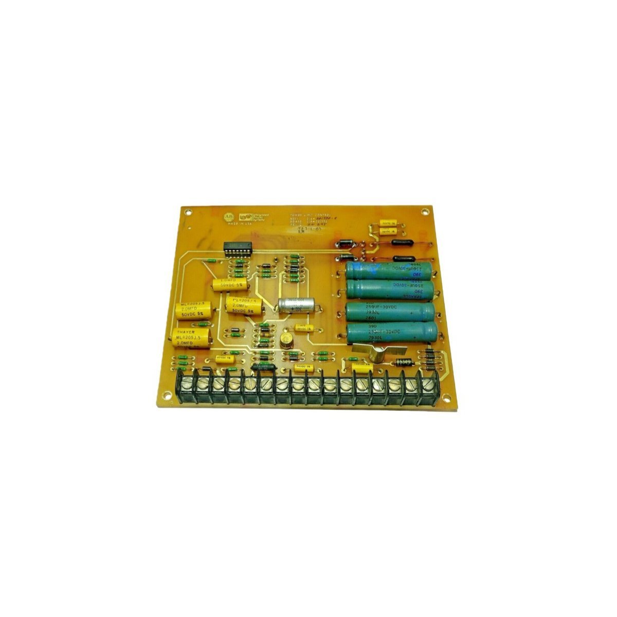
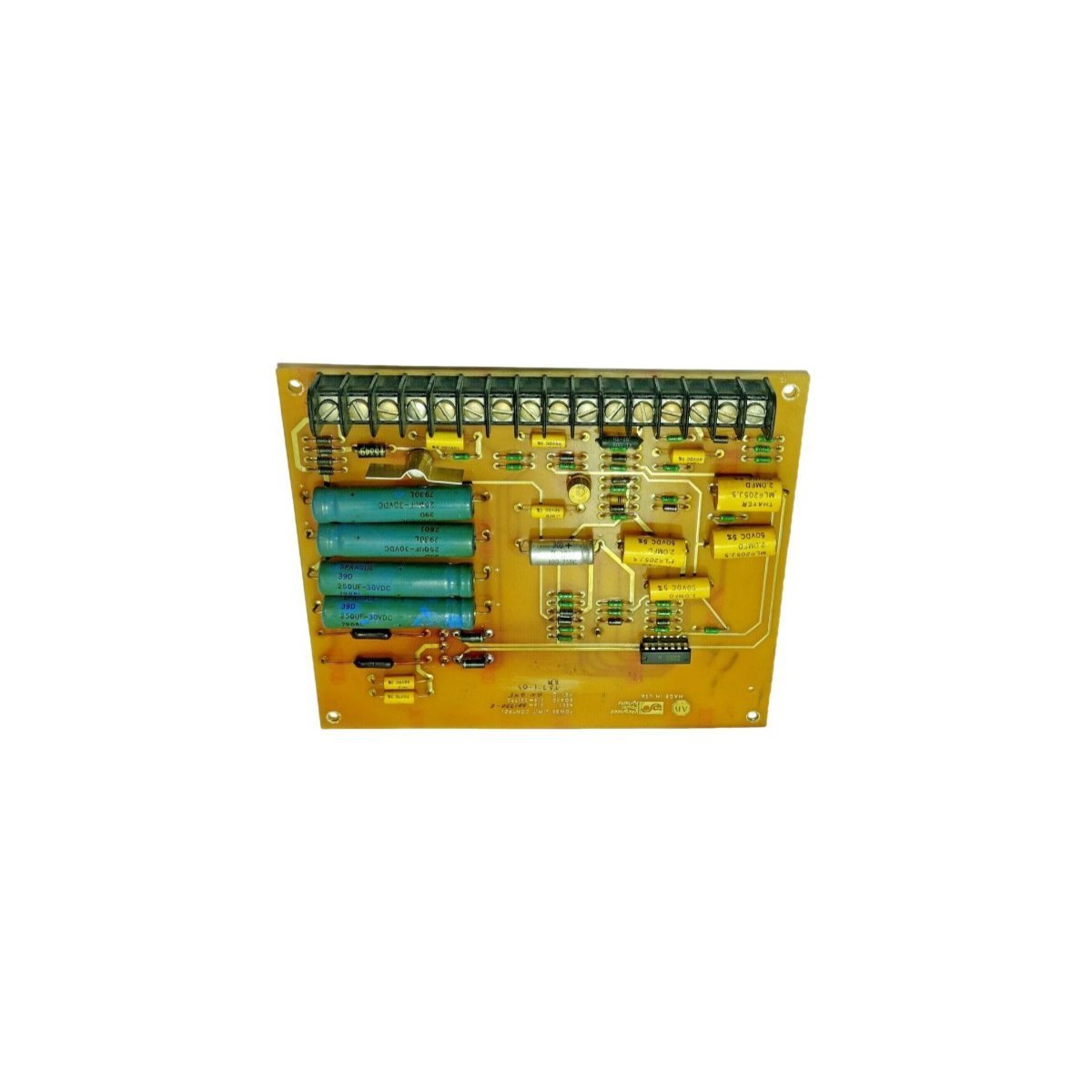
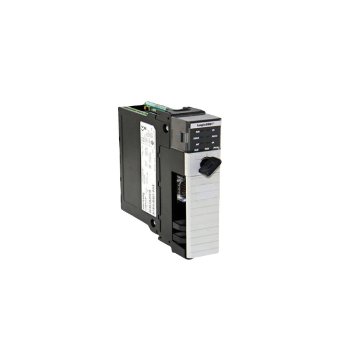
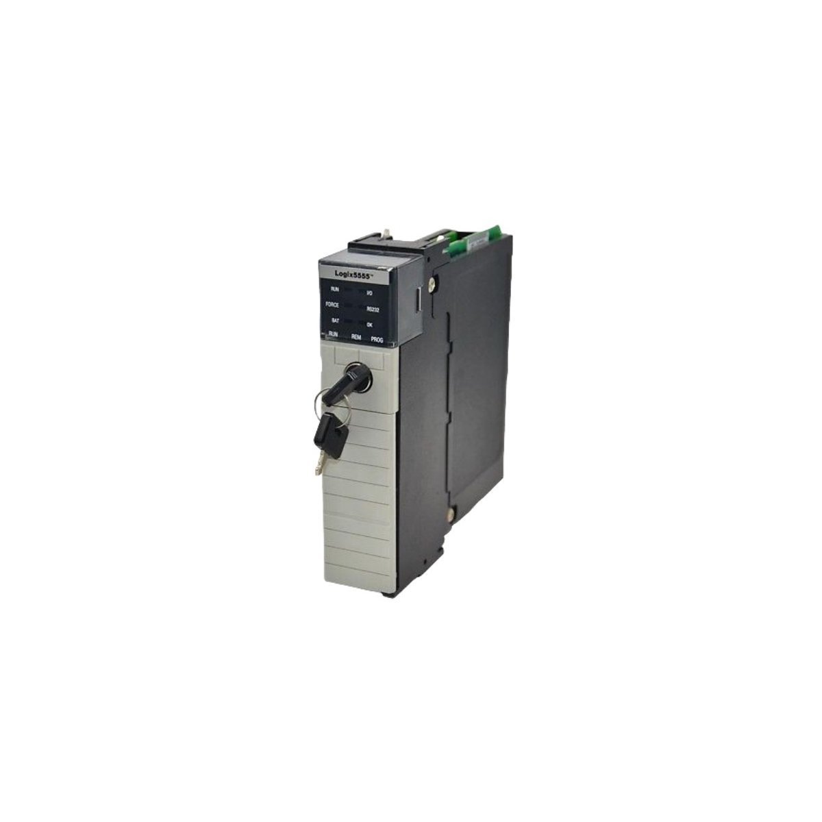
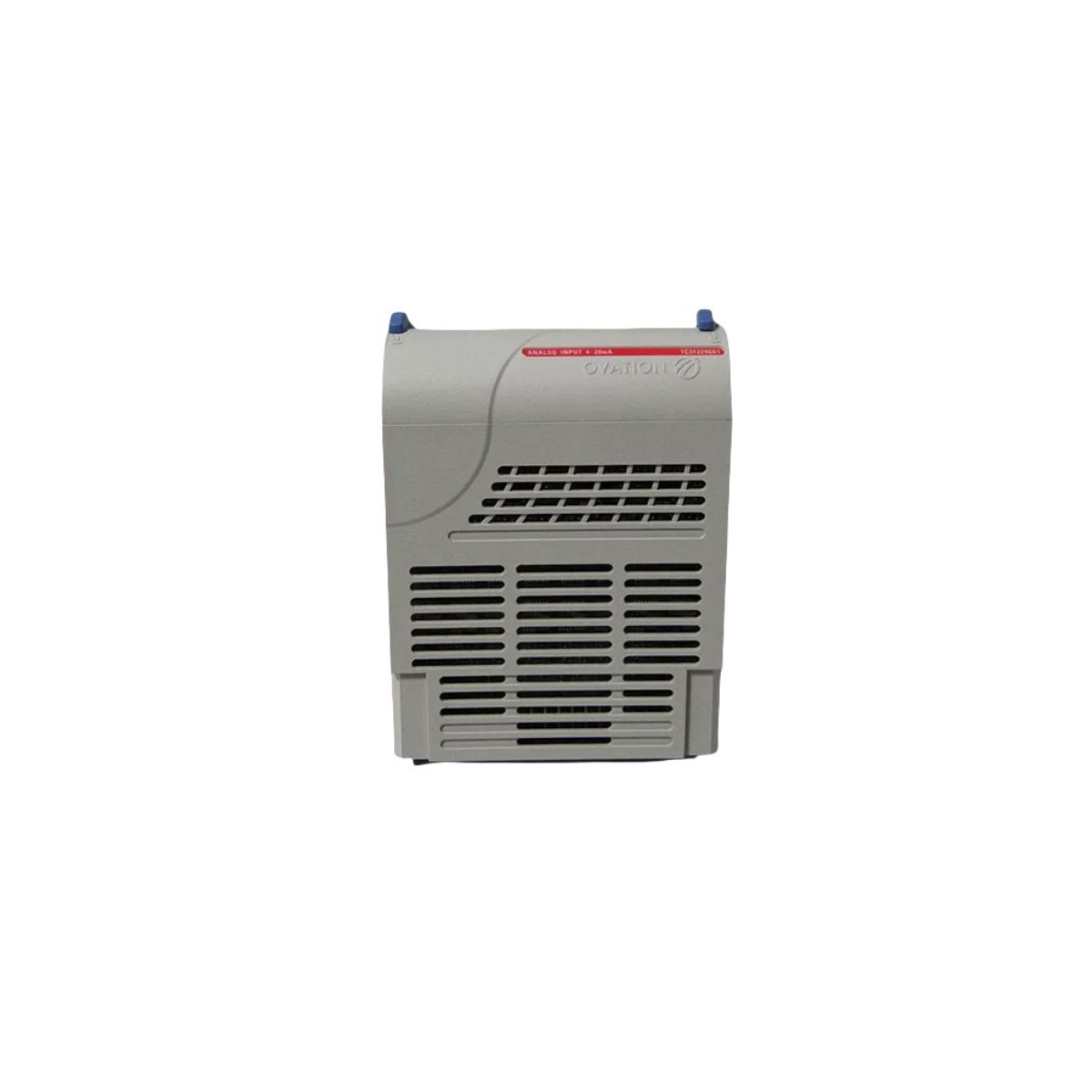
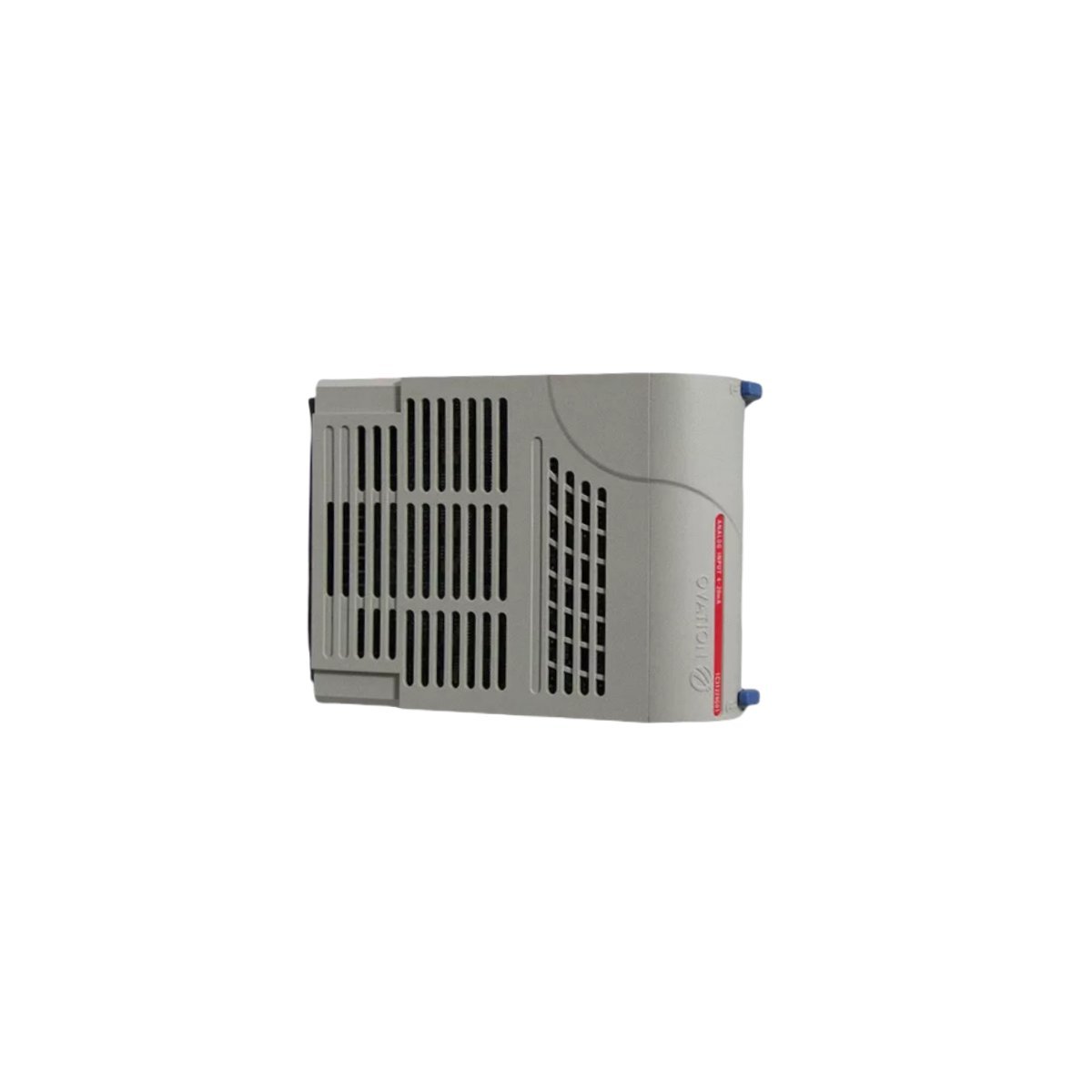
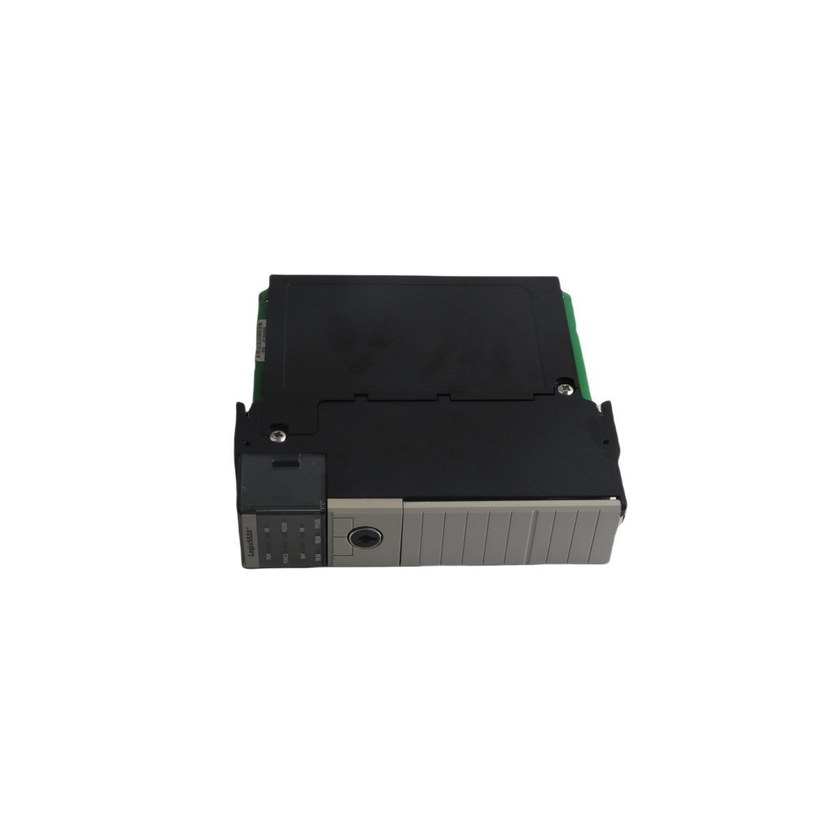
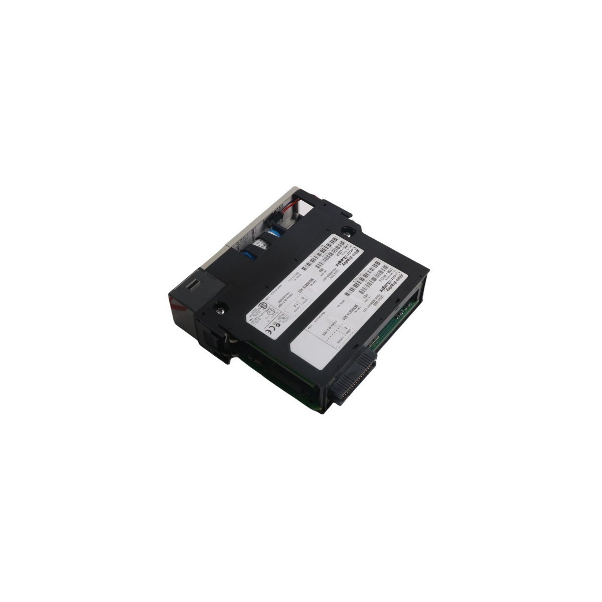
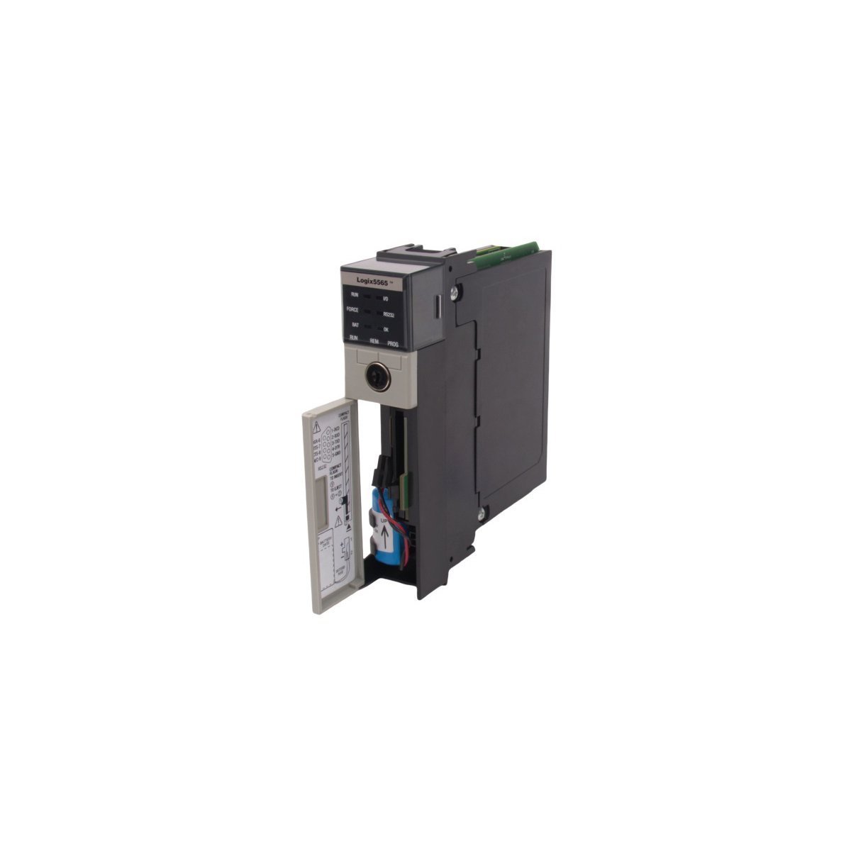
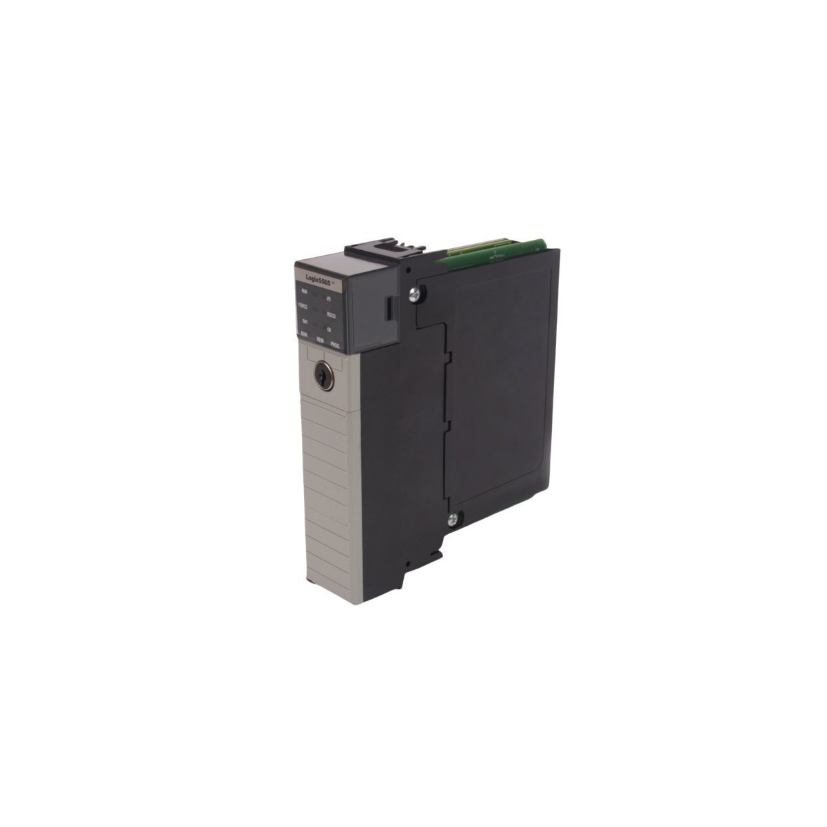
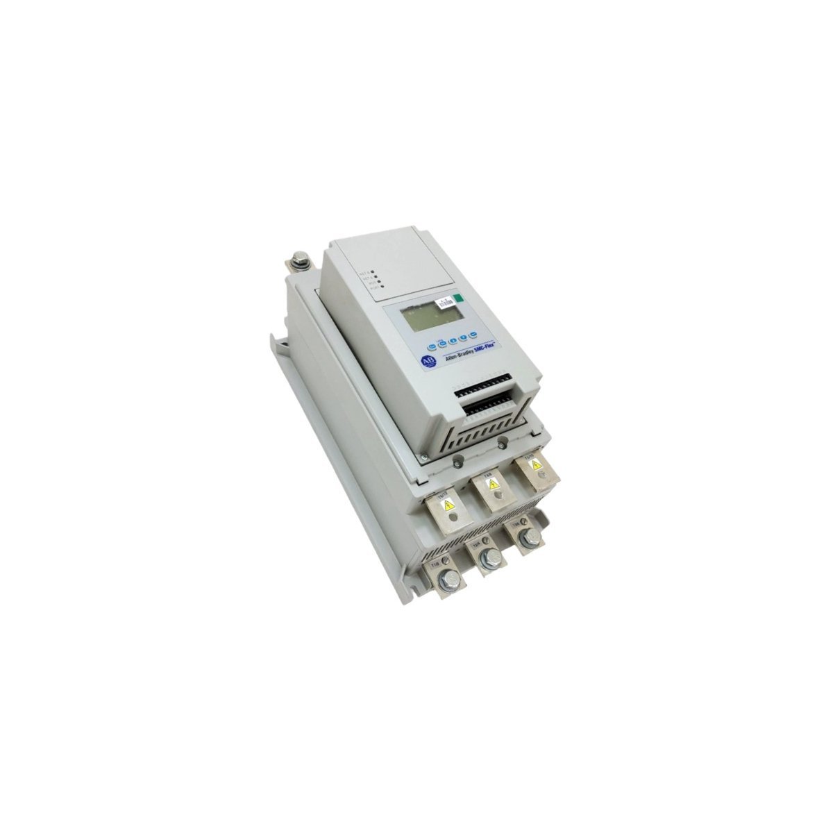
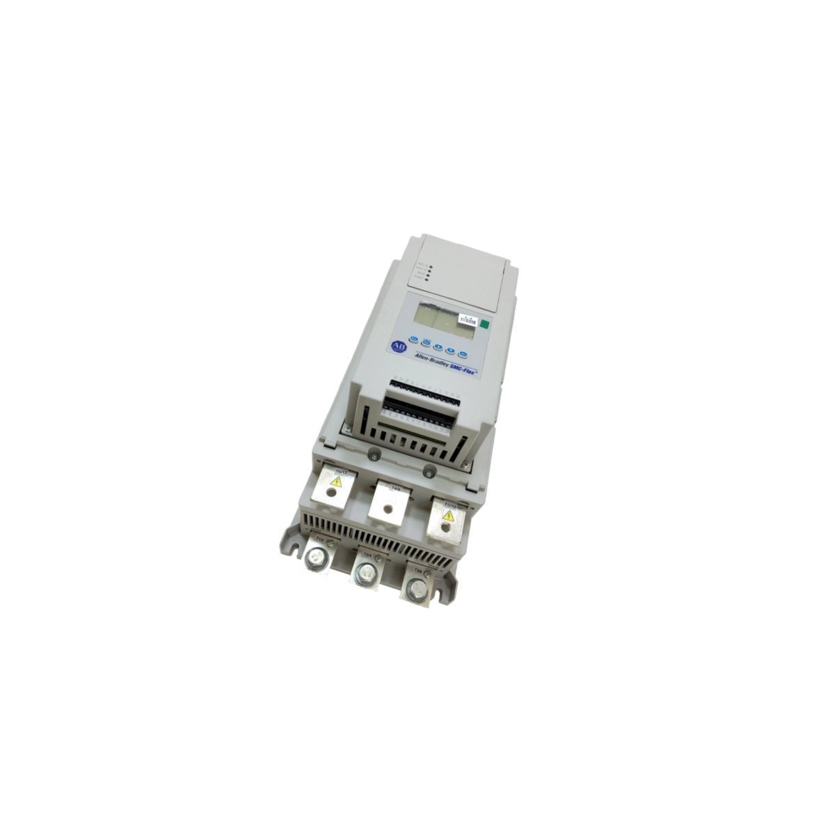
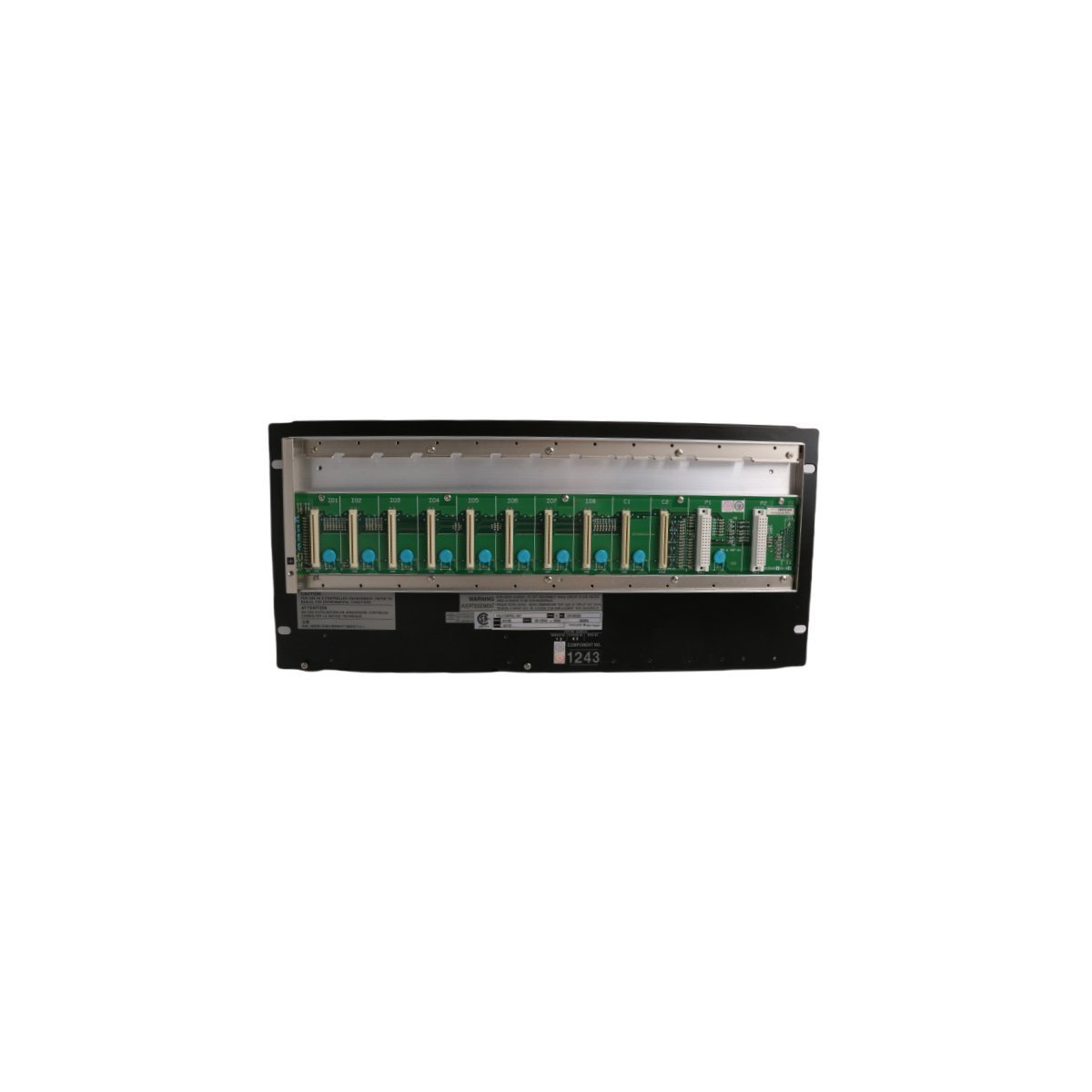
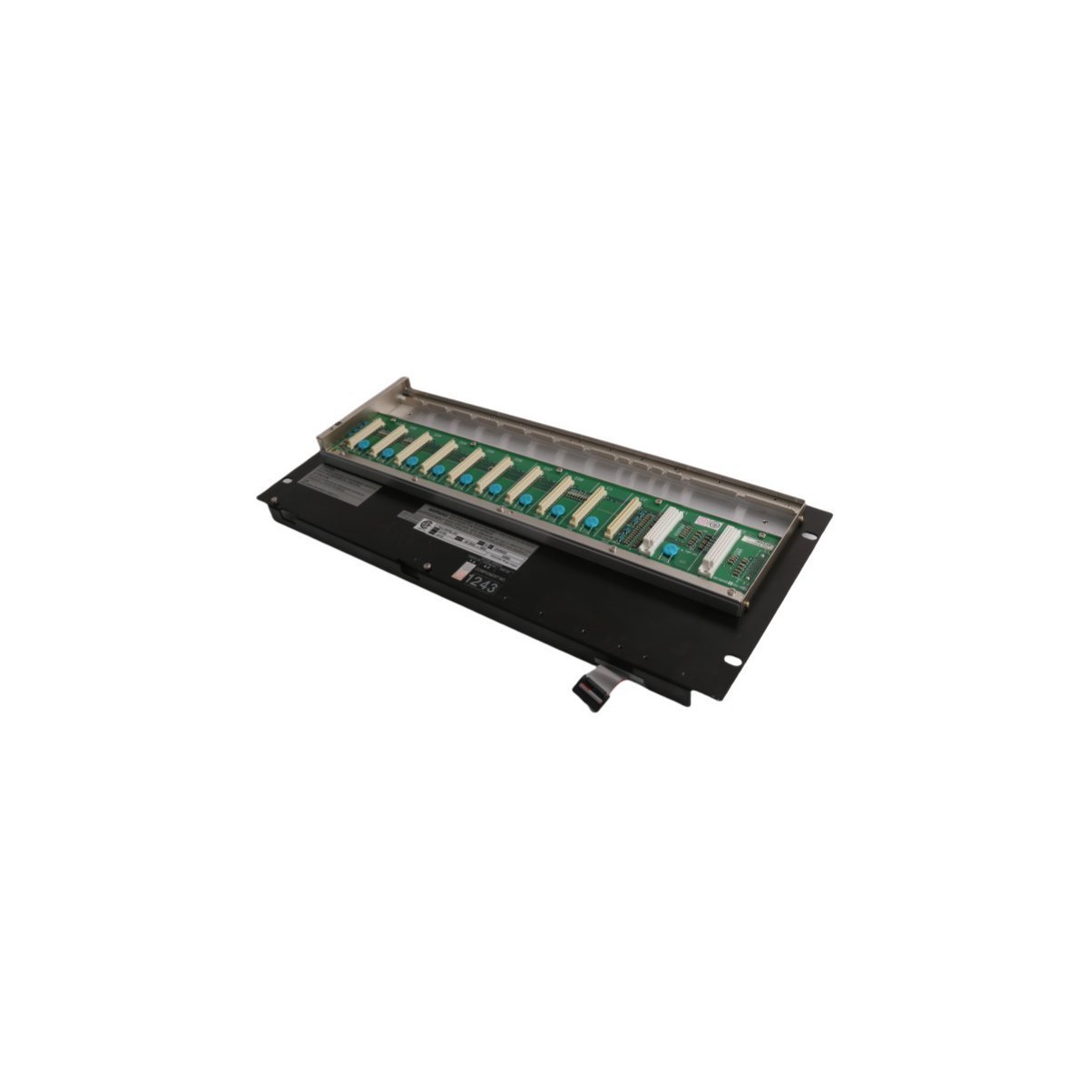
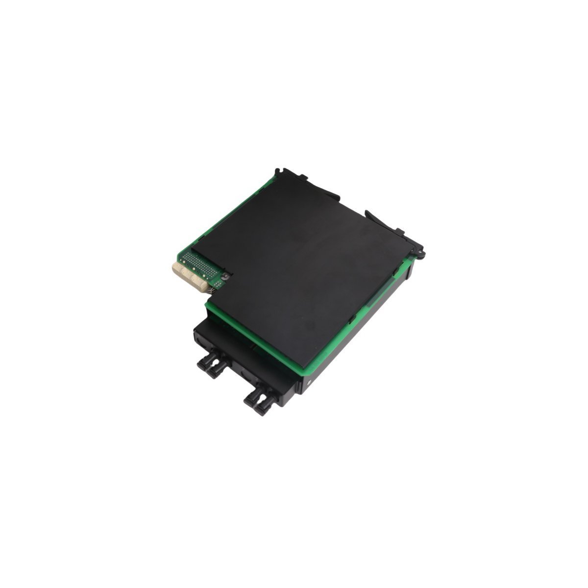
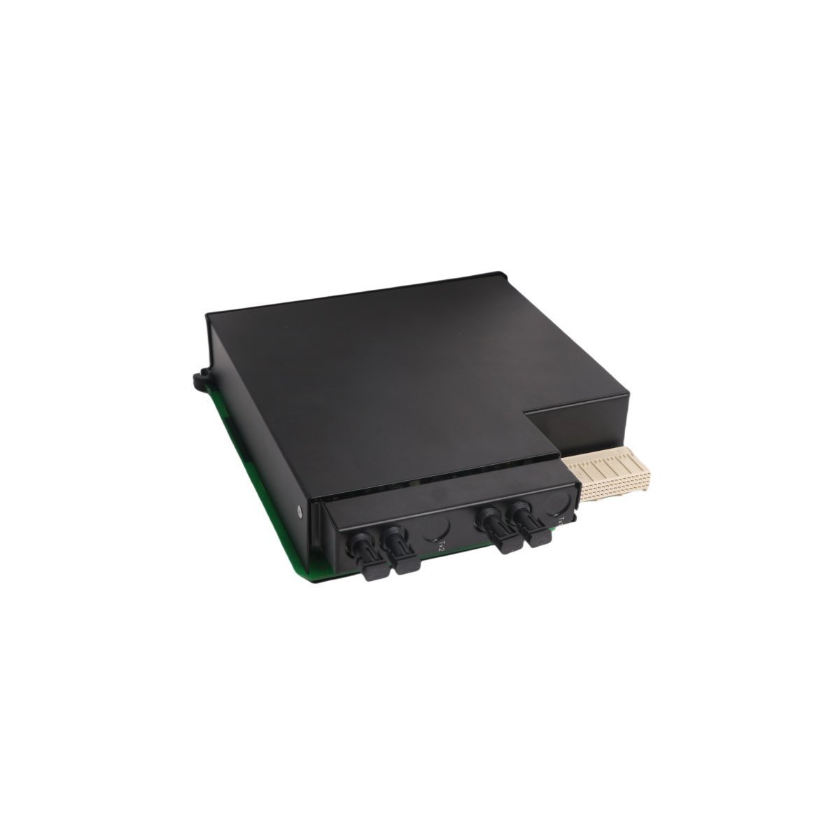
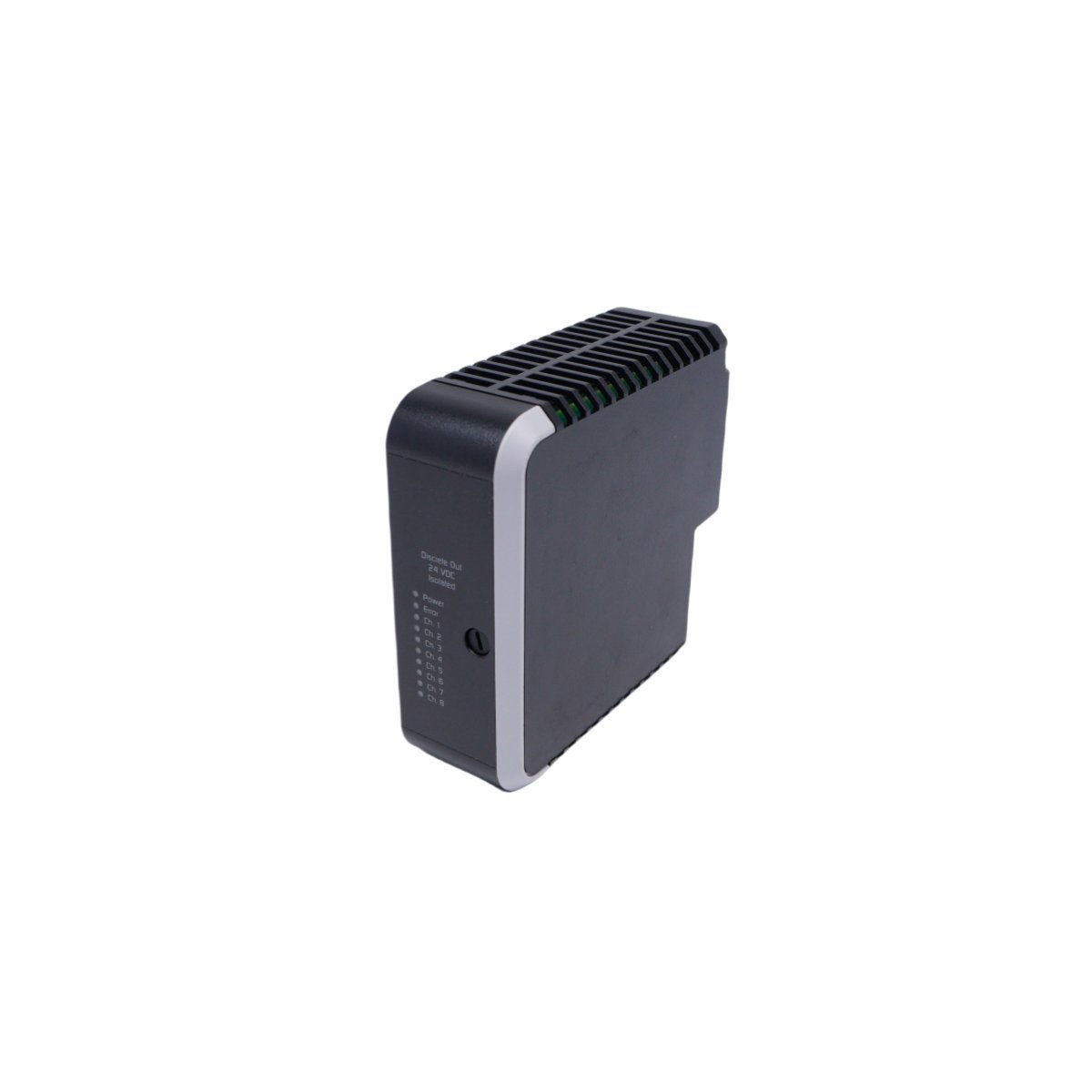
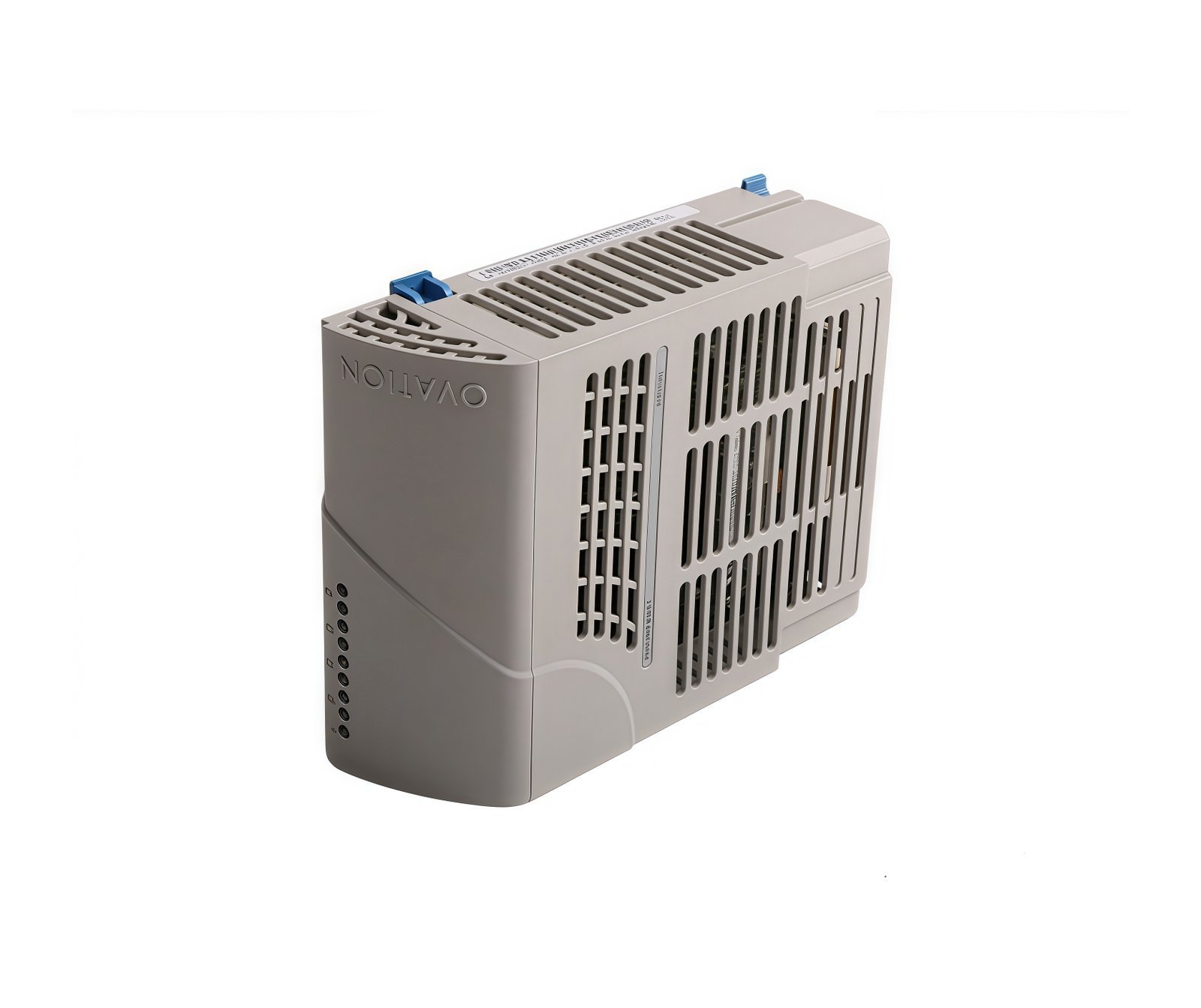
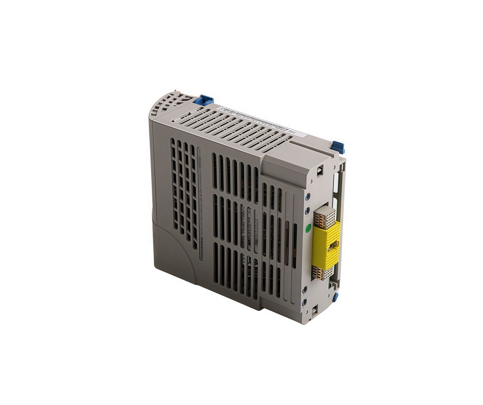
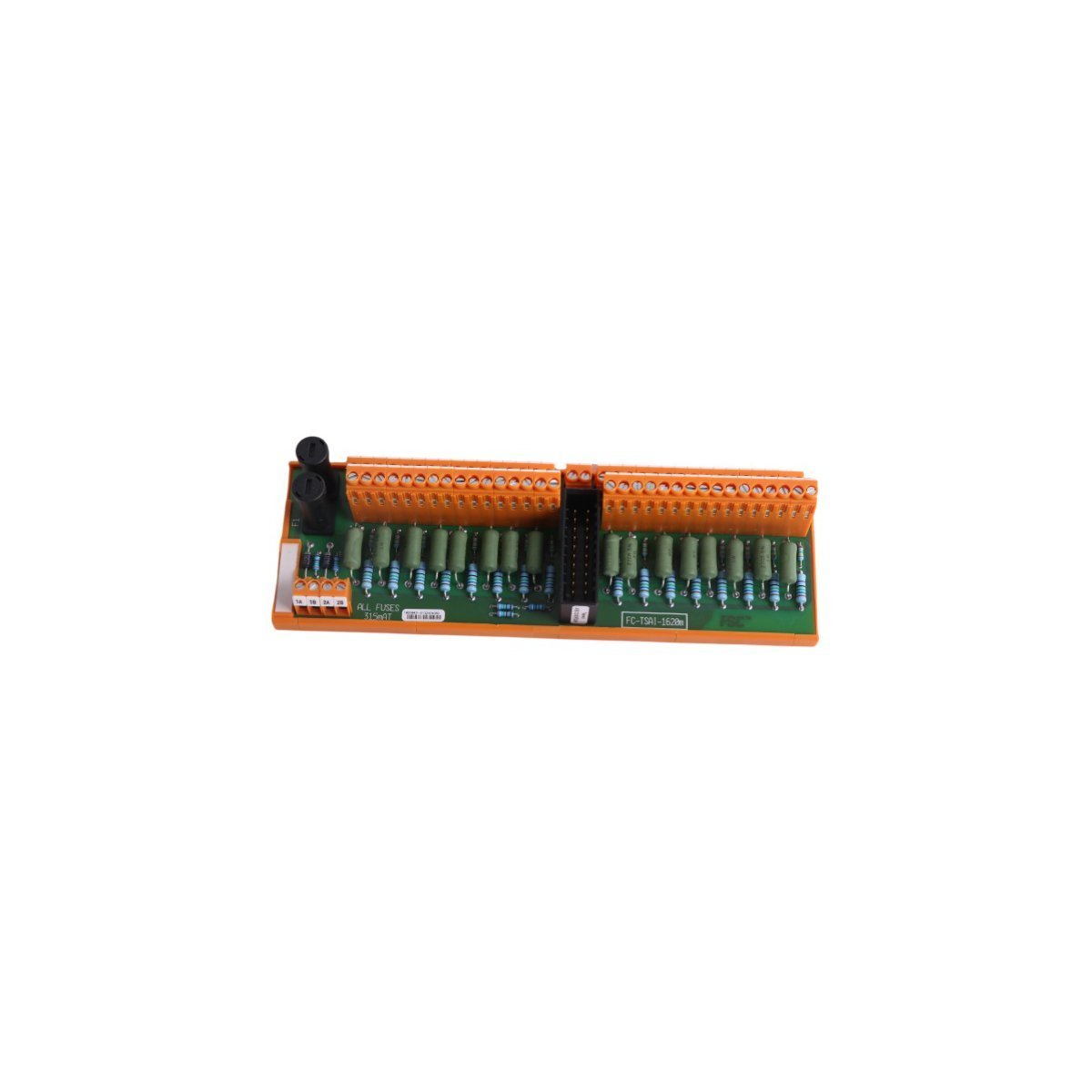
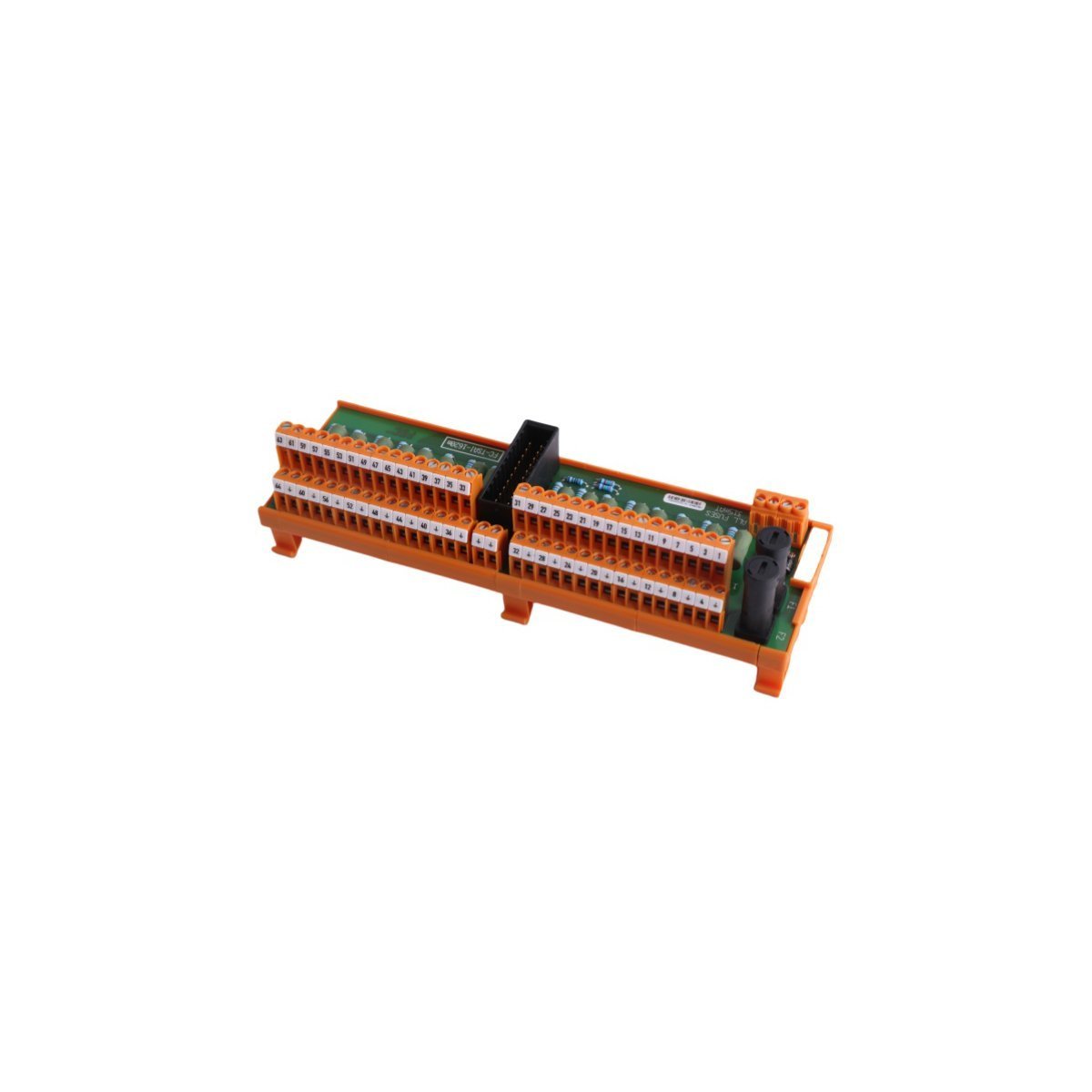
Allen-Bradley 018-001770 Power Limit Control Board
Configured for precise power management and electrical protection within industrial control architectures, the Allen-Bradley 018-001770 (018-001770 Power Limit Control Board) provides direct physical monitoring and regulation of power thresholds for PLC-based systems.
Hardware Specifications
| Parameter | Specification |
| Model | 018-001770 |
| Brand | Allen-Bradley |
| Origin | USA |
| Weight | 0.9 kg |
| Dimensions | 3.5 cm x 13 cm x 14.5 cm |
| Operating Temp | Standard industrial range |
| Power Consumption | Not specified |
| Primary Function | Power limit regulation |
Industrial Control System Connectivity
The 018-001770 integrates seamlessly into industrial control platforms, which utilize backplane bus communication velocity protocols for real-time monitoring. This module architecture facilitates I/O density scaling within the control cabinet, allowing the system to coordinate power limiting across multiple feedback loops. Furthermore, the board supports firmware flash compatibility, which enables engineers to align board logic with system-wide operational requirements. Consequently, the hardware ensures deterministic response times during power threshold excursions.
Frequently Asked Questions (FAQ)
Q: Does this board support hot-swapping under load?A: No, the 018-001770 must be isolated from all power sources and control signals before extraction or insertion to prevent damage to the backplane interface or onboard circuitry.Q: How is the power limit threshold configured on this module?A: Threshold parameters are managed via the host PLC software configuration, which interacts with the board's internal logic to enforce established voltage or current limits.Field Installation Guidelines
- To begin with, ensure all power to the rack is strictly isolated before attempting to insert the module into the designated slot; consequently, this prevents potential electrical shorts.
- Subsequently, seat the board firmly into the backplane connector until fully engaged; furthermore, secure the front-panel retaining screws to ensure structural stability against continuous industrial vibration.
- In addition, when connecting signal wiring, verify that all shields are terminated at the designated ground rail to minimize electromagnetic interference; meanwhile, ensure all cable stress is relieved to prevent connector fatigue.
- Following physical mounting, perform a thorough continuity check before applying power to the cabinet; by doing so, you verify that the board is correctly indexed within the system.
- Finally, as a last step, confirm that the system software parameters match the hardware ID of the 018-001770 to enable accurate communication and data exchange on the bus.