


Sale!
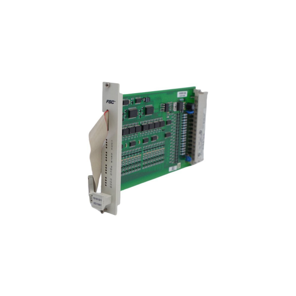
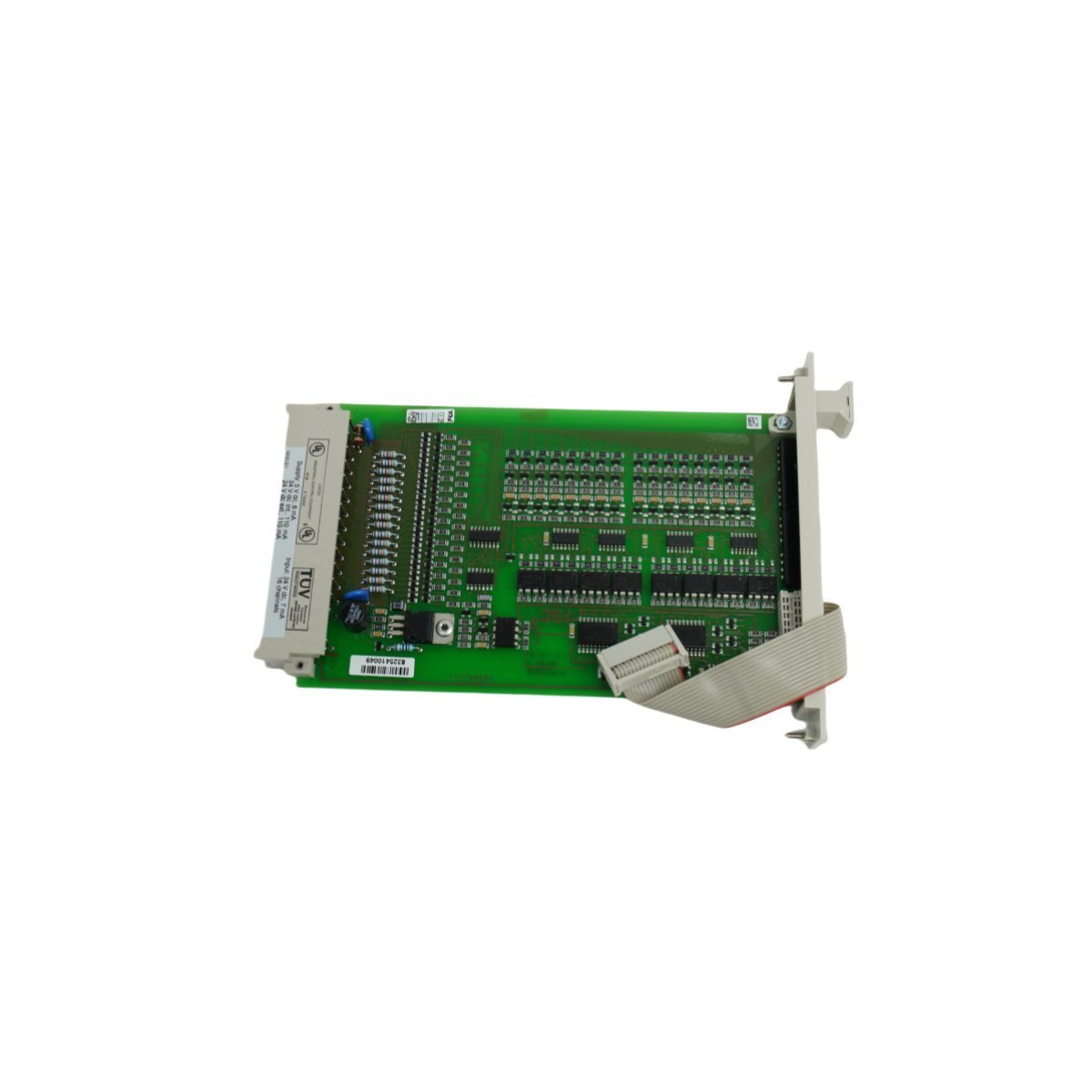
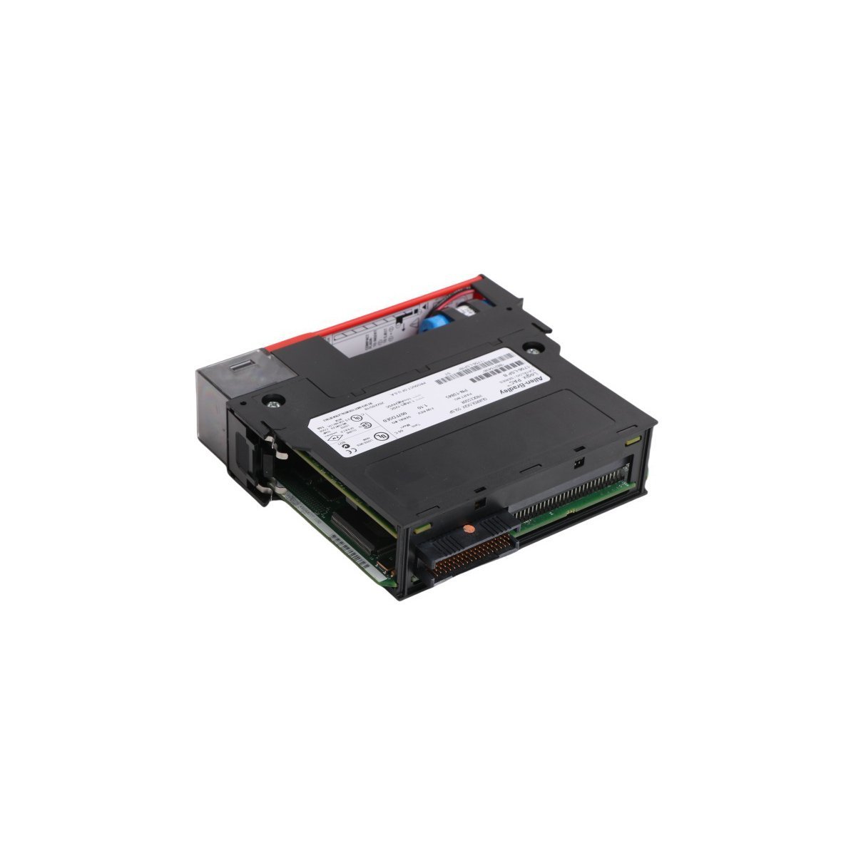
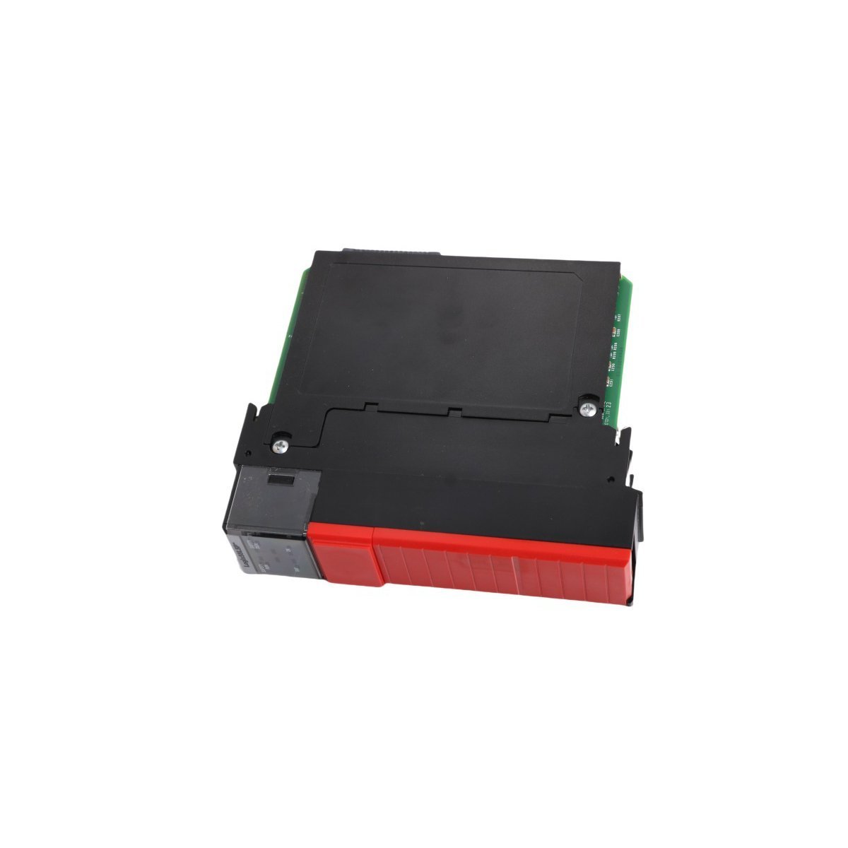
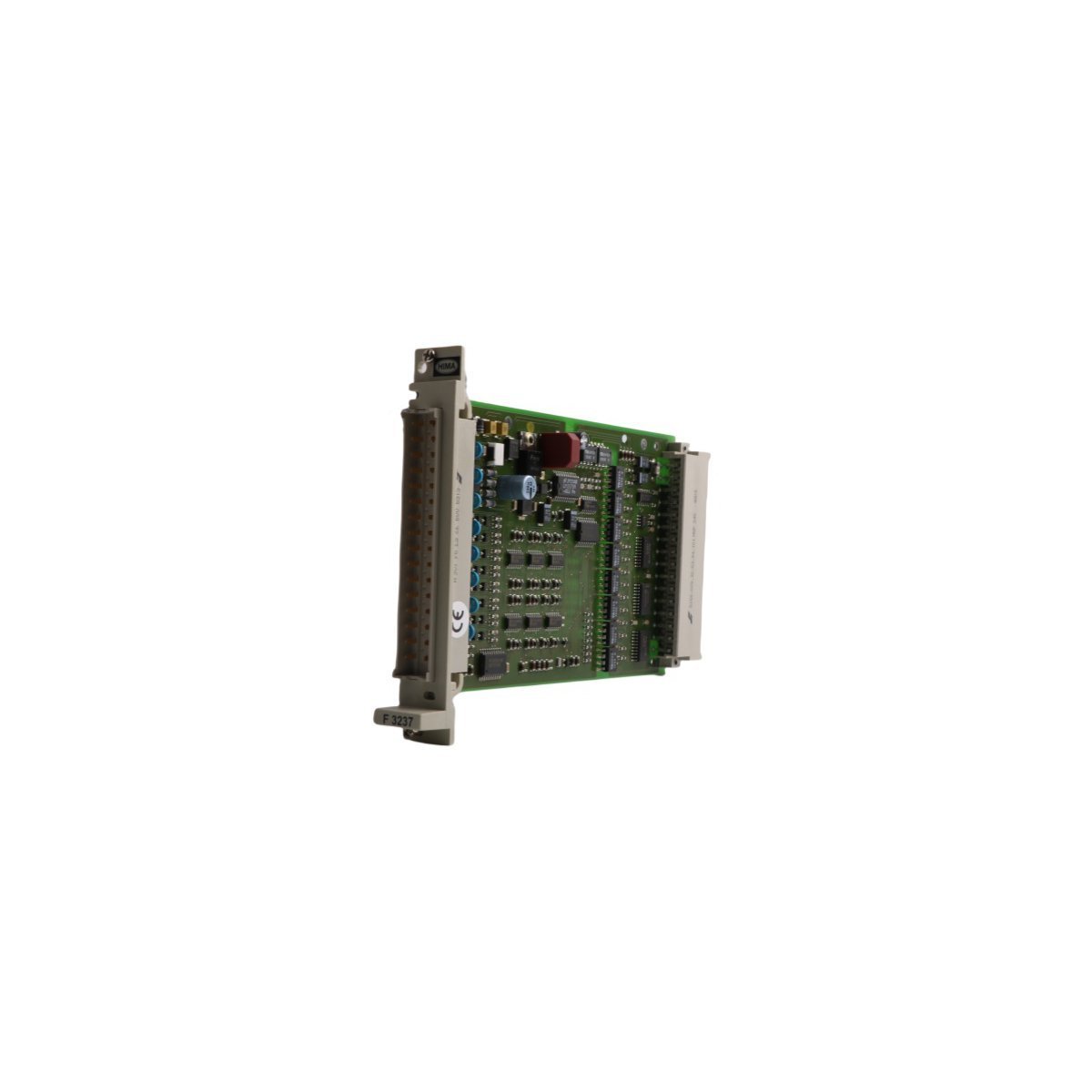
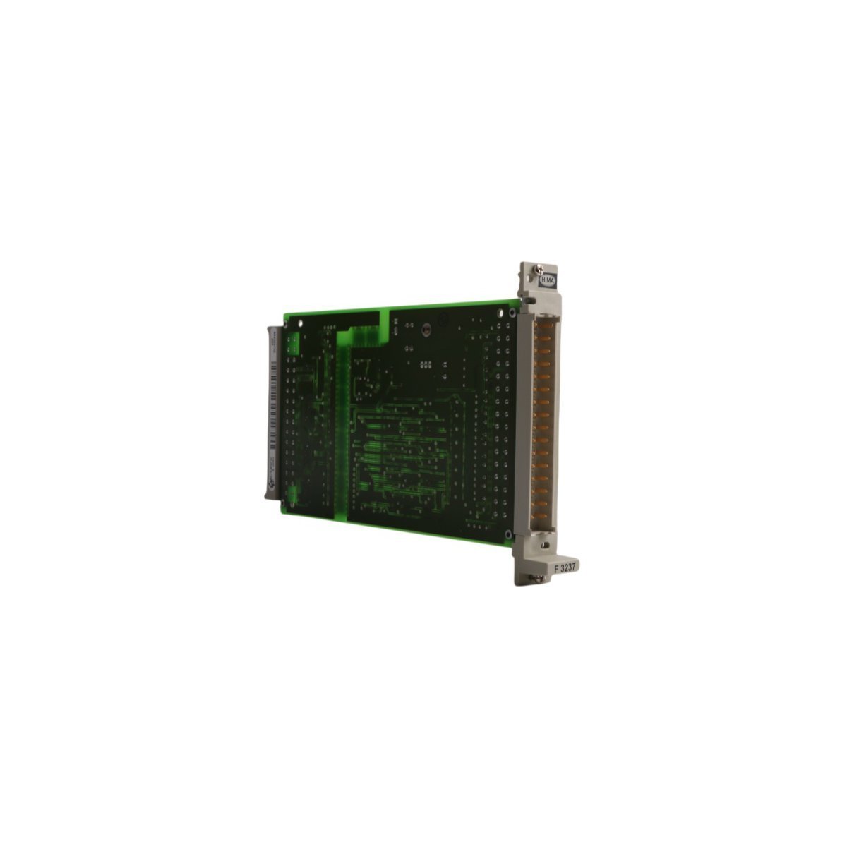
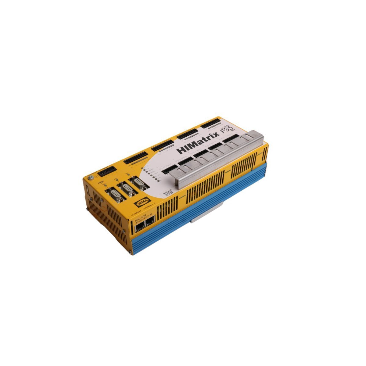
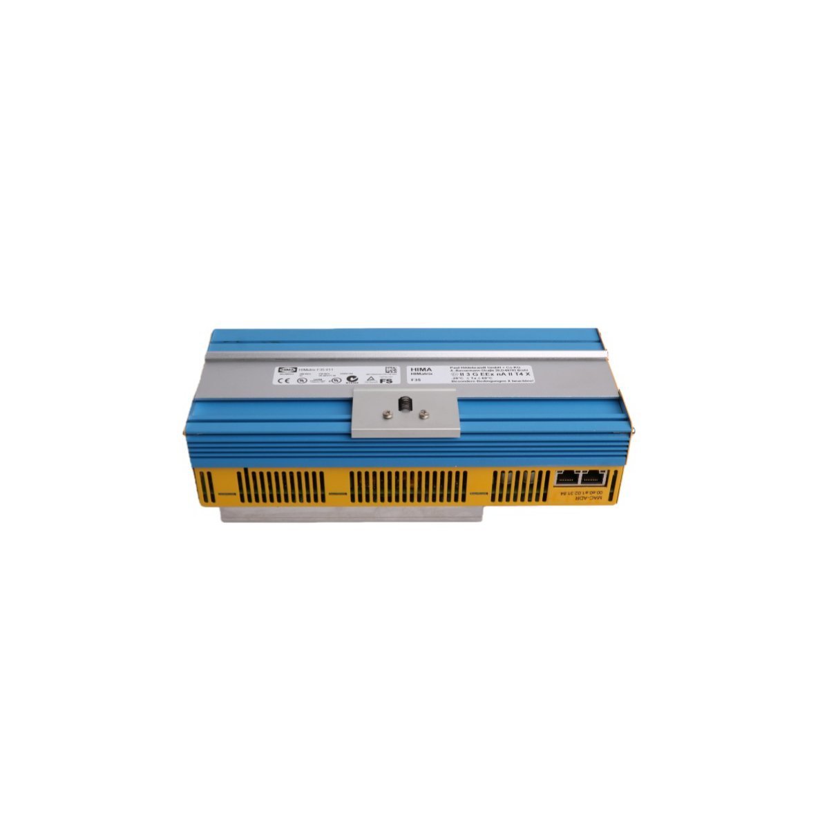
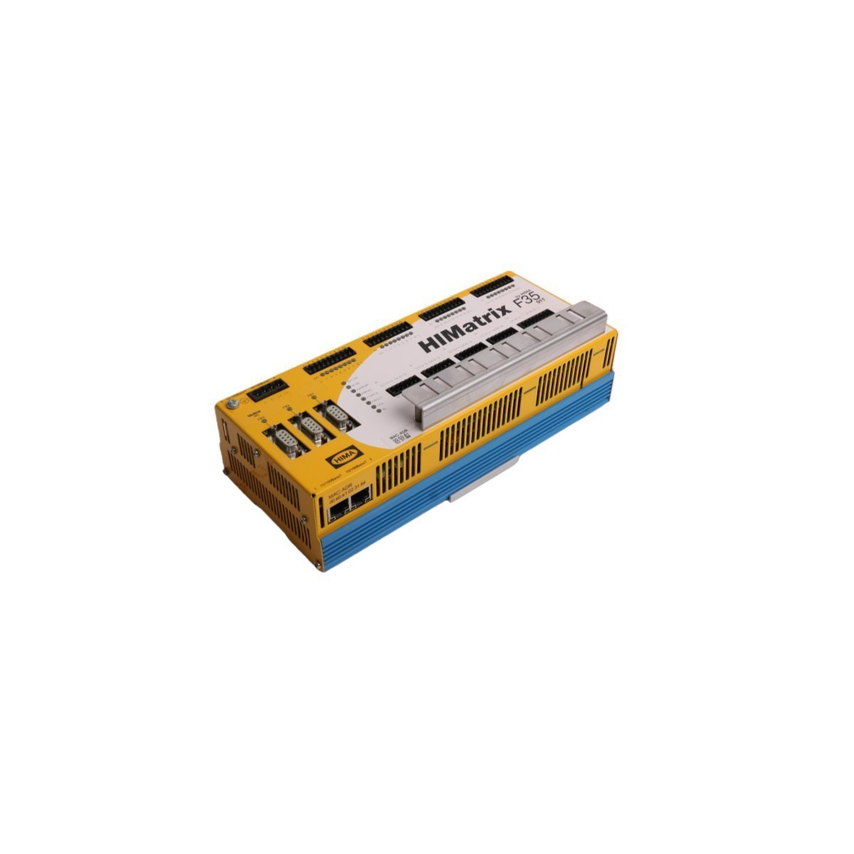
HONEYWELL 10101/2/1 FSC Fail-Safe Digital Input Module
Purchase the legacy HONEYWELL 10101/2/1 FSC Digital Input Module. Verified original stock to support your existing safety control infrastructure. Contact us for pricing.
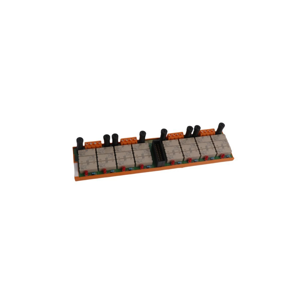
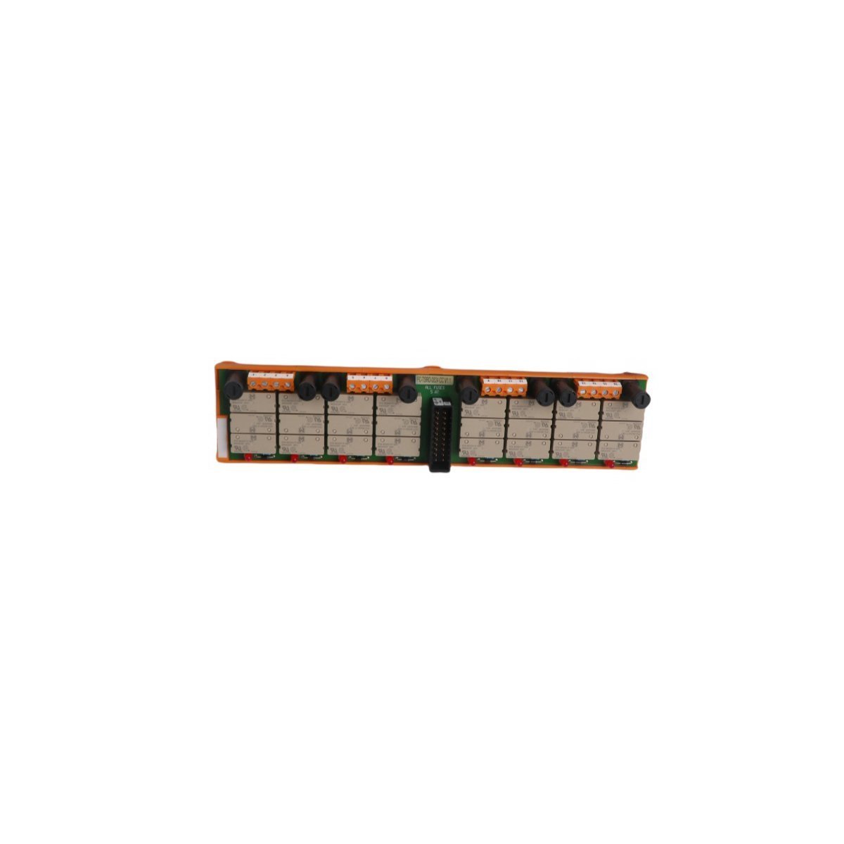
Order genuine Honeywell FTA-T-15 Fail-Safe Termination boards for your safety control system. Certified original stock with worldwide shipping and standard warranty.
The HONEYWELL FTA-T-15 is a highly specialized Field Termination Assembly (FTA) engineered for Honeywell’s legacy Fail Safe Control (FSC) systems. Operating within critical Safety Instrumented Systems (SIS), this termination interface bridges field-side discrete binary sensors (such as limit switches, safety interlocks, and emergency stop buttons) and the upstream fail-safe digital input modules of the control architecture.
| Parameter | Specification |
|---|---|
| Model Number | FTA-T-15 |
| Brand | HONEYWELL |
| Origin | USA |
| Module Type | Fail-Safe Digital Input Field Termination Assembly (FTA) |
| Range of Product | Fail Safe Control (FSC) System |
| Communication Support | Modbus RTU interface pathways |
| Weight | 0.46 kg |
| Dimensions | 15.0 x 7.0 x 5.8 cm |
| System Classification | DCS / Emergency Shutdown (ESD) / Safety System |
| Lifecycle Status | Active (Legacy Support/Spares Inventory) |
Unlike standard commercial digital termination boards, the FTA-T-15 is purpose-built to maintain high fault-tolerance requirements up to Safety Integrity Level 3 (SIL3) loops:


We are committed to protecting your privacy. The information collected here is strictly used to provide the requested quotes, technical support, and relevant industrial automation solutions.