


Sale!
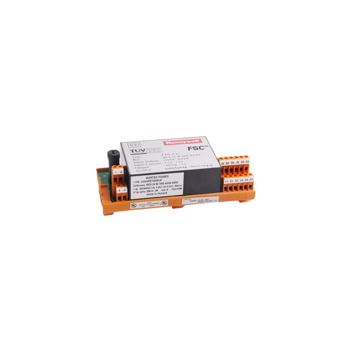
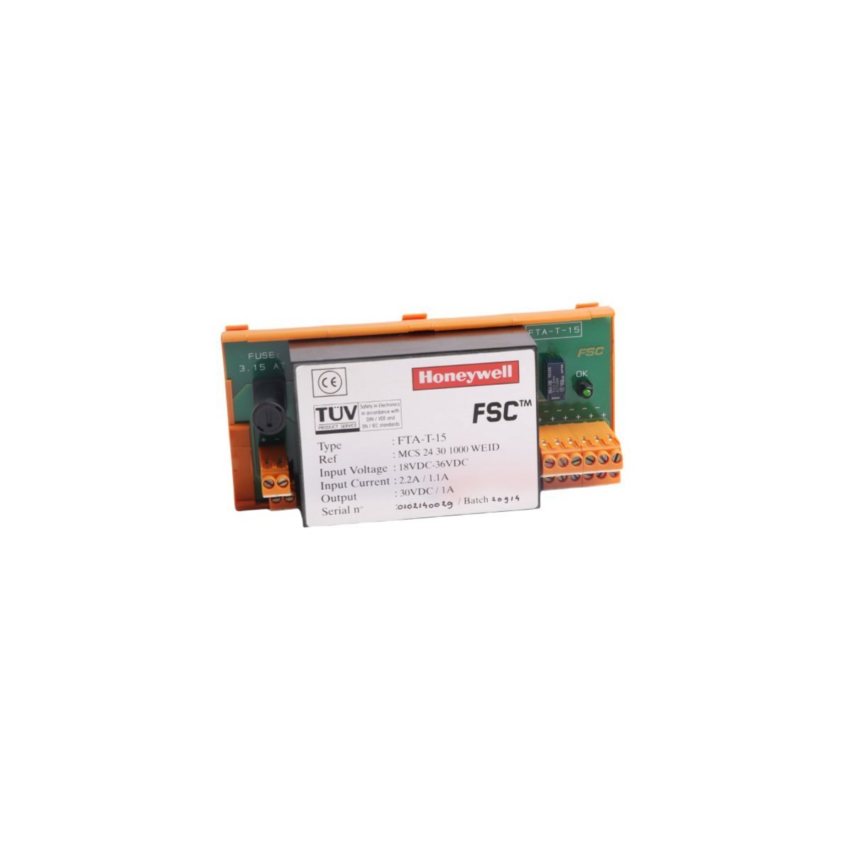
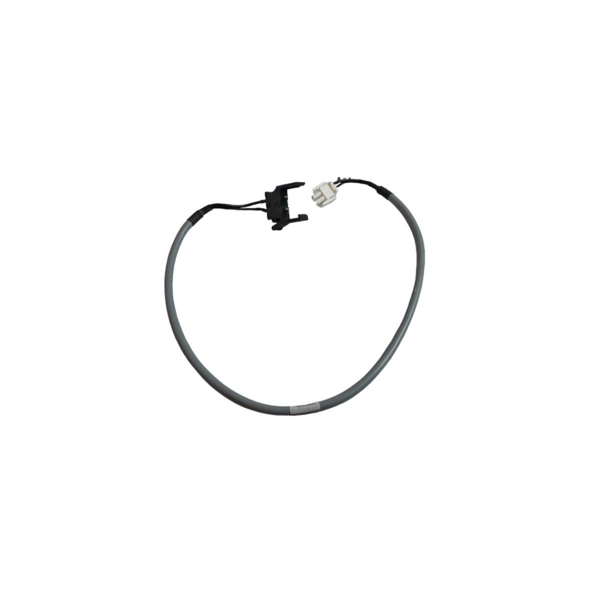
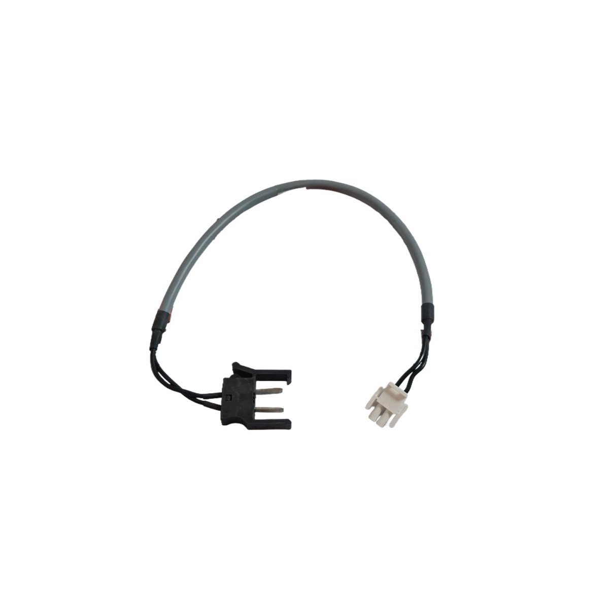
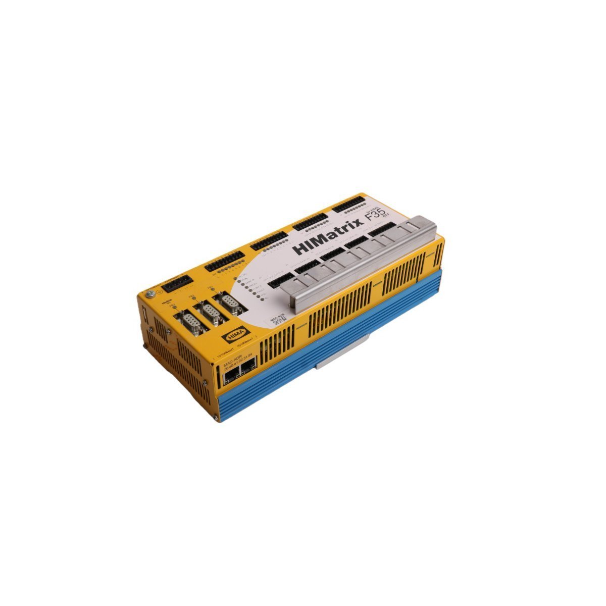
HONEYWELL FTA-T-15 Fail-Safe Termination Assembly
Order genuine Honeywell FTA-T-15 Fail-Safe Termination boards for your safety control system. Certified original stock with worldwide shipping and standard warranty.
Purchase the HONEYWELL FC-TSRO-0824 V1.1 Digital Output Field Termination Assembly. Brand New, Original Stock, with verified global logistics and technical warranty protection. Request your quote.
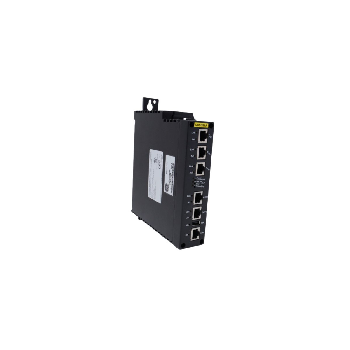
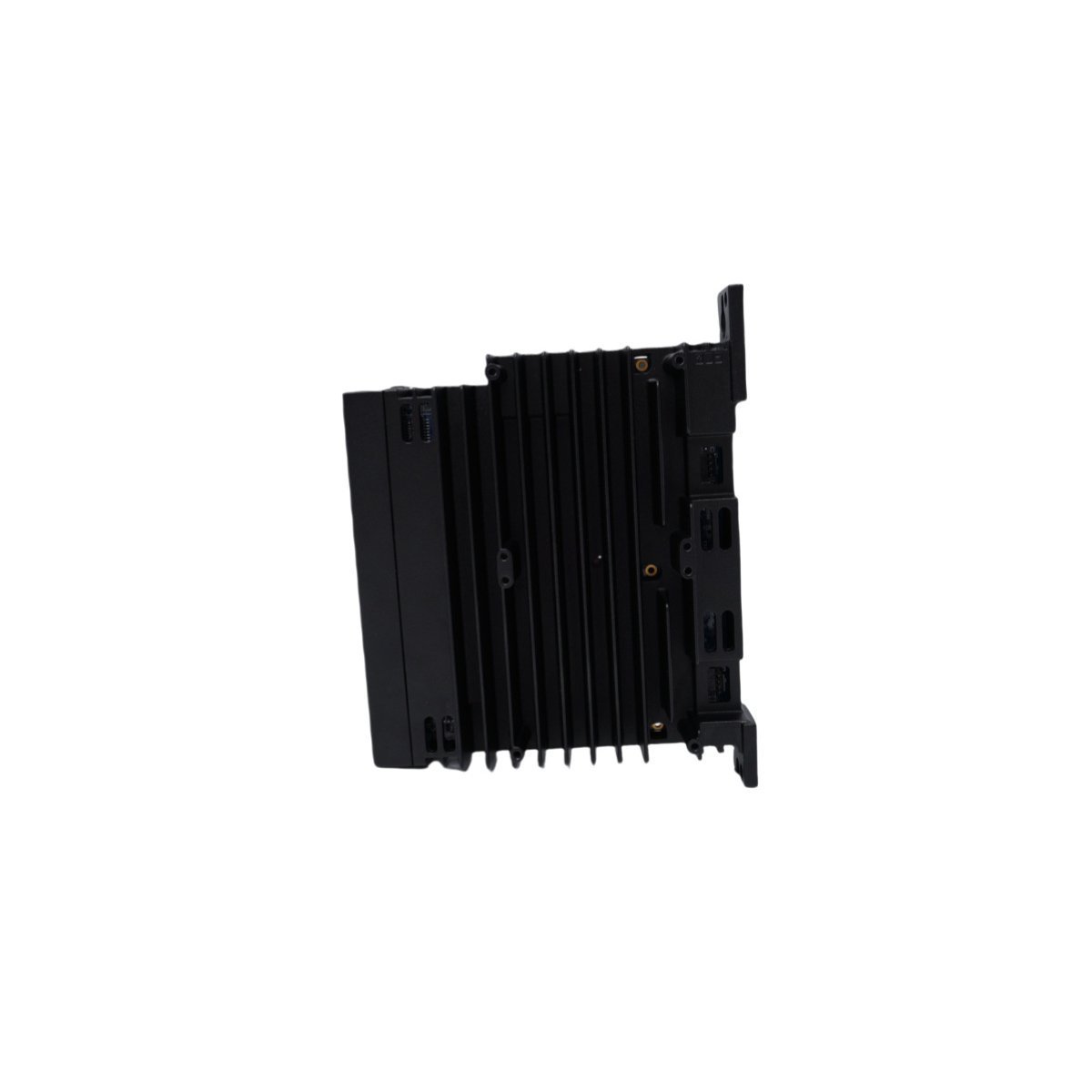
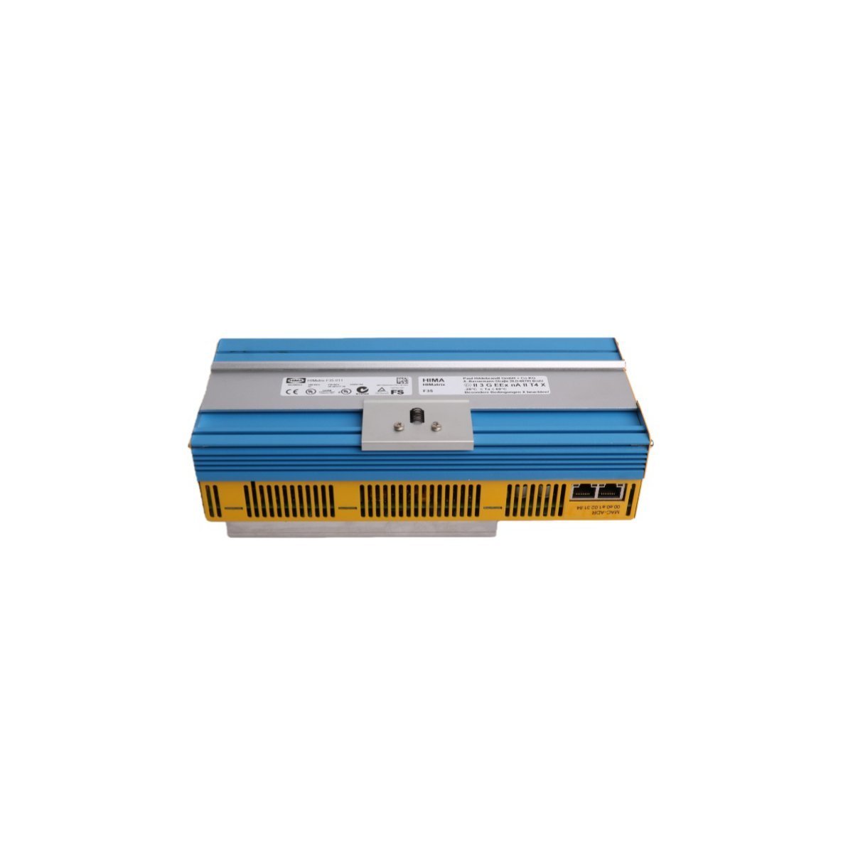
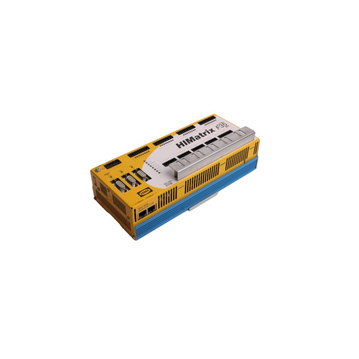
The HONEYWELL FC-TSRO-0824 V1.1 serves as the primary FC-TSRO-0824 Digital Output Field Termination Assembly utilized to execute fail-safe state execution across Safety Instrumented System (SIS) and Safety Manager platforms. The hardware functions as a critical physical interface layer between internal electronic logic solvers and external high-power field actuators.
| Parameter | Specification |
|---|---|
| Model | FC-TSRO-0824 V1.1 |
| Brand | HONEYWELL |
| Origin | USA |
| Weight | 0.5 kg |
| Dimensions | 30 x 7 x 6.2 cm |
| Ingress Protection | IP20 |
| Communication Interface | RS-485 Modbus RTU |
| Output Current Rating | 2 A per channel maximum |
| Base Accuracy | +/- 2% of full scale |
| System Compatibility | Honeywell Safety Manager / Safety System |
The module architecture is engineered for SIL3 certification compliance, incorporating triple modular redundancy (TMR) 2oo3 architecture options when paired with corresponding safety logic solvers. Complete galvanic isolation barriers isolate high-voltage external field circuits from the internal low-voltage backplane components, mitigating diagnostic faults and preventing cascading damage. The device continuously executes internal diagnostic routines to ensure strict fail-safe state execution, enabling immediate de-energization or controlled shutdown paths upon detecting systematic runtime anomalies.
Q: Does the assembly support live physical replacement during continuous process operations?
A: Yes, the system supports hot-swap maintenance under powered conditions, provided that surrounding loop bypass interlocks are properly configured to prevent inadvertent trips.
Q: What is the significance of the integrated RS-485 Modbus RTU interface on this unit?
A: The serial link allows secondary diagnostic telemetry mapping and sequence-of-events reporting to external DCS routers without affecting the primary safety function.


We are committed to protecting your privacy. The information collected here is strictly used to provide the requested quotes, technical support, and relevant industrial automation solutions.