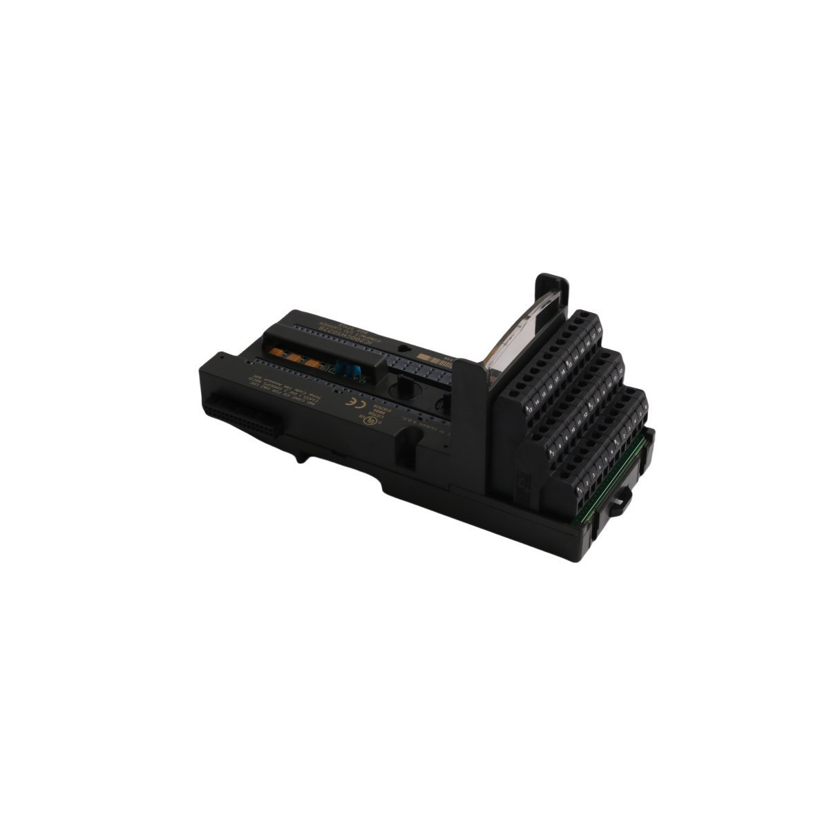
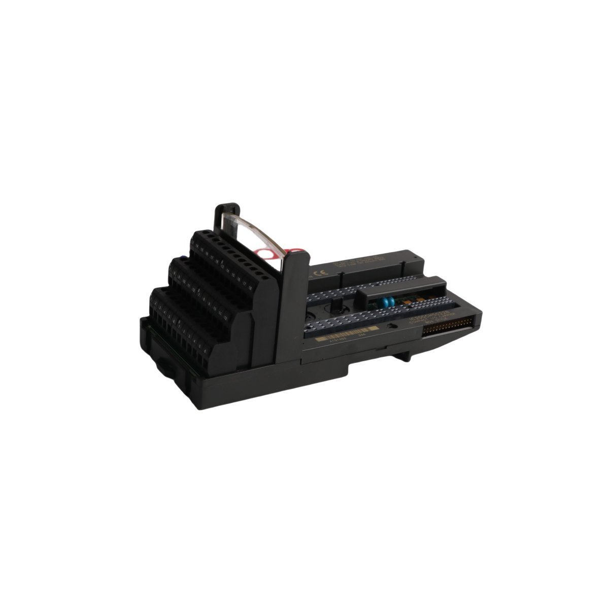
Buy new Honeywell FS-IOBUS-CPIO6 I/O Bus module. Essential for extending controller-to-I/O chassis communication in Safety Manager platforms. Features 34-pole latch connectors for positions 1 to 6. Secure original surplus ready for immediate export.
The HONEYWELL FS-IOBUS-CPIO6 is a robust I/O Bus control chassis engineered specifically for Honeywell Safety Manager systems. It acts as a vital communication link between the core controller chassis and remote or localized I/O chassis, facilitating safe, deterministic data transfer across critical industrial automation environments.
This specific module is designated for installation inside extension cabinets, handling I/O routing pathways for positions 1 through 6. It manages high-integrity signaling to expand system capacity while maintaining the stringent timing margins necessary for safety-instrumented systems (SIS).
Technical Specifications
Parameter
Specification
Model Number
FS-IOBUS-CPIO6
Manufacturer
Honeywell
Product Range
Safety Manager
Module Type
I/O BUS In Extension Cabinet (Positions 1 to 6)
Physical Dimensions
24 x 18.8 x 6.5 cm
Weight
0.4 kg
Connector Configuration
34-pole latch connectors (Male on top, Female on remaining sides)
Communication Profile
Dedicated high-speed synchronous I/O bus
Compliance & Approvals
UL Listed, CSA Certified
System Classification
Distributed Control System (DCS) / Safety Instrumented System (SIS)
Lifecycle Status
Legacy (Discontinued by manufacturer on Dec 31, 2018)
HS Code
8537101190
Functional Design & Bus Routing
The mechanical and electrical architecture of the FS-IOBUS-CPIO6 is optimized for modular multi-chassis configurations. It utilizes high-density 34-pole latch connectors to chain I/O signals through physical equipment racks.
Top Connector: Features a male 34-pole latch interface designed to receive the upstream bus link coming from the main controller or previous extension node.
Side Connectors: Feature female latching sockets to pass the buffered I/O bus signals downward or laterally to consecutive chassis racks in positions 1 through 6.
This structured vertical/lateral interconnect design eliminates complex field terminal wiring, minimizes signal attenuation, and guarantees low-latency communication loops across long, multi-rack cabinet enclosures.
Frequently Asked Questions
Q: Can the FS-IOBUS-CPIO6 be used interchangeably in any cabinet position?
A: No. The FS-IOBUS-CPIO6 is specifically mapped and electrically optimized for extension cabinet arrangements covering positions 1 through 6. Installing the module outside its designated positions can cause addressing mismatches or signal degradation on the safety bus.
Q: Since this part was discontinued in 2018, how can I ensure compatibility with existing systems?
A: As a standard hardware component of the legacy Honeywell Safety Manager platform, the FS-IOBUS-CPIO6 maintains direct drop-in backward compatibility with active Safety Manager systems using identical physical slot spacing and 34-pole ribbon cables.
Q: Does this chassis module require an independent IP address for configuration?
A: No. The FS-IOBUS-CPIO6 operates as a deterministic hardware routing layer for the internal I/O bus. It is configured transparently via the master Safety Manager engineering software through the parent controller’s hardware tree, requiring no individual network IP assignment.
Field Installation Guidelines
Chassis Alignment & Seating: Mount the module securely onto the cabinet subpanel or DIN rail support frame. Ensure all locking tabs are engaged to prevent vibration-induced signal dropouts.
Cable Strain Relief: When routing the heavy 34-pole flat ribbon cables into the male and female latch connectors, always apply proper strain relief loops. Avoid tight bends that can damage the internal conductor foil.
Bus Termination Verification: Always verify that the final downstream chassis in the extension loop is terminated properly according to Honeywell Safety Manager specifications to suppress signal reflections on the I/O bus.
Static Discharge Precautions: Handle the module using appropriate ESD (electrostatic discharge) wrist straps during installation or replacement to prevent damage to the backplane communication logic.
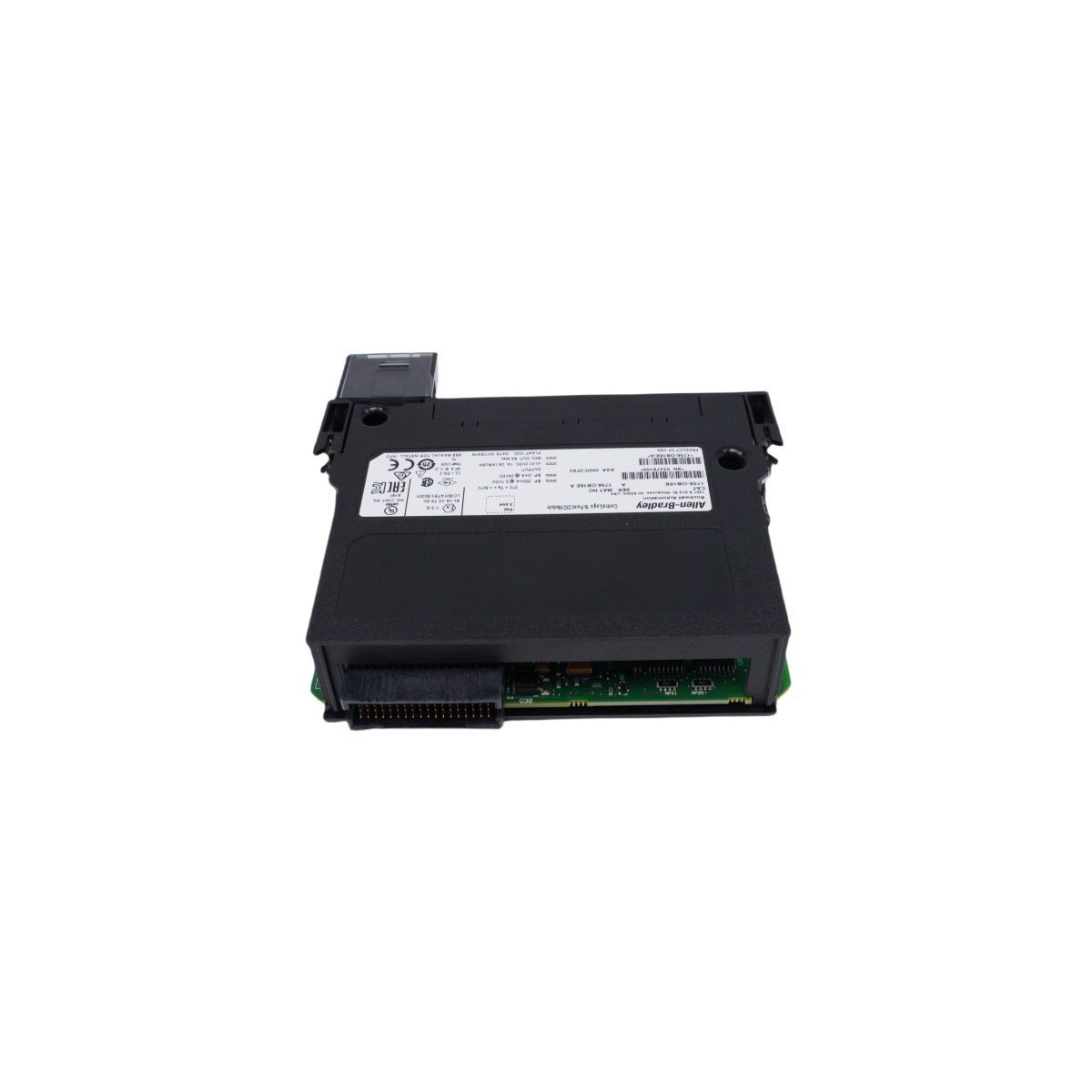
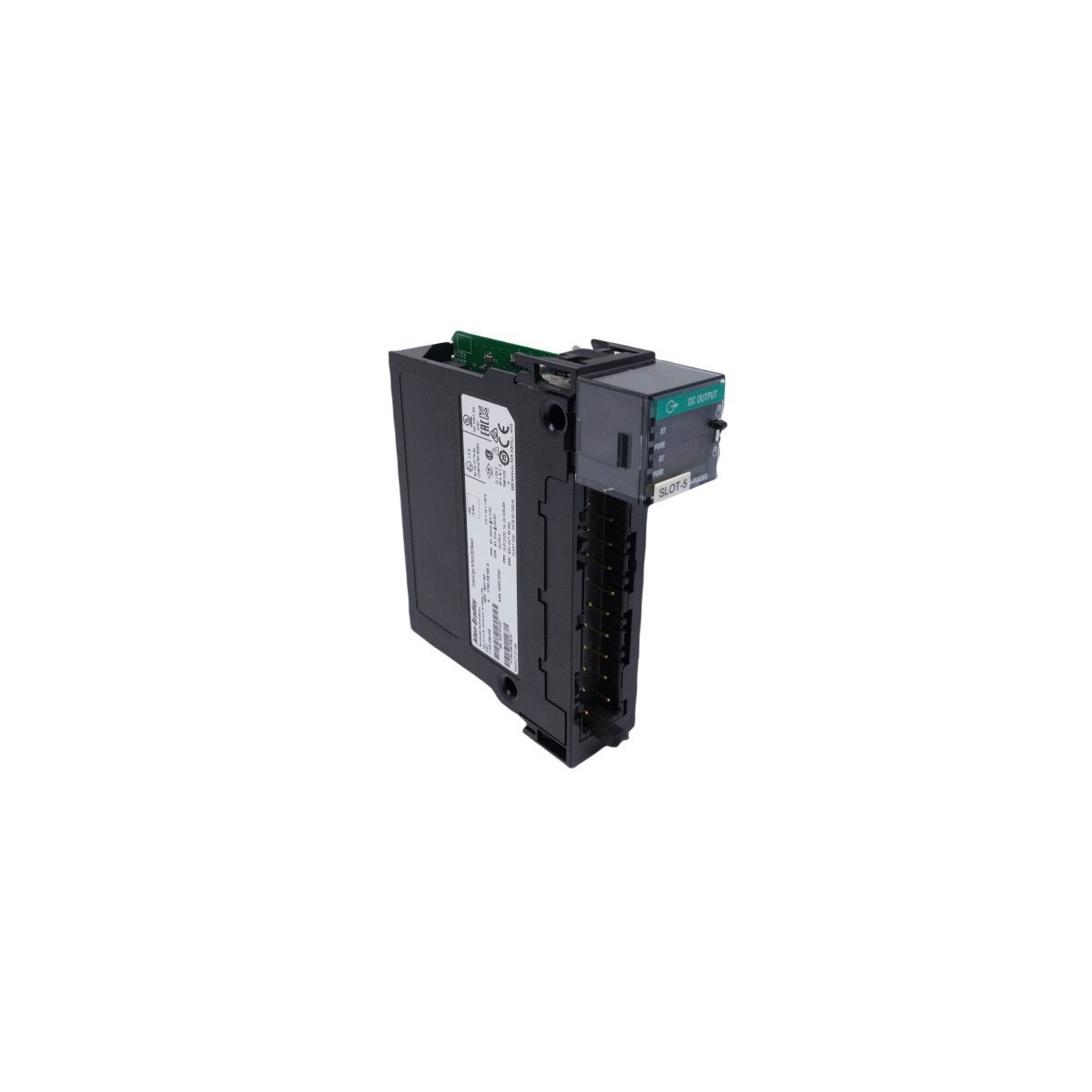
Get the genuine Allen-Bradley 1756-OB16E ControlLogix Discrete Output Module featuring 16 electronically fused points and 24 VDC sourcing outputs. Discontinued Spare, Original Surplus with Global Shipping. Minimize automation downtime now.
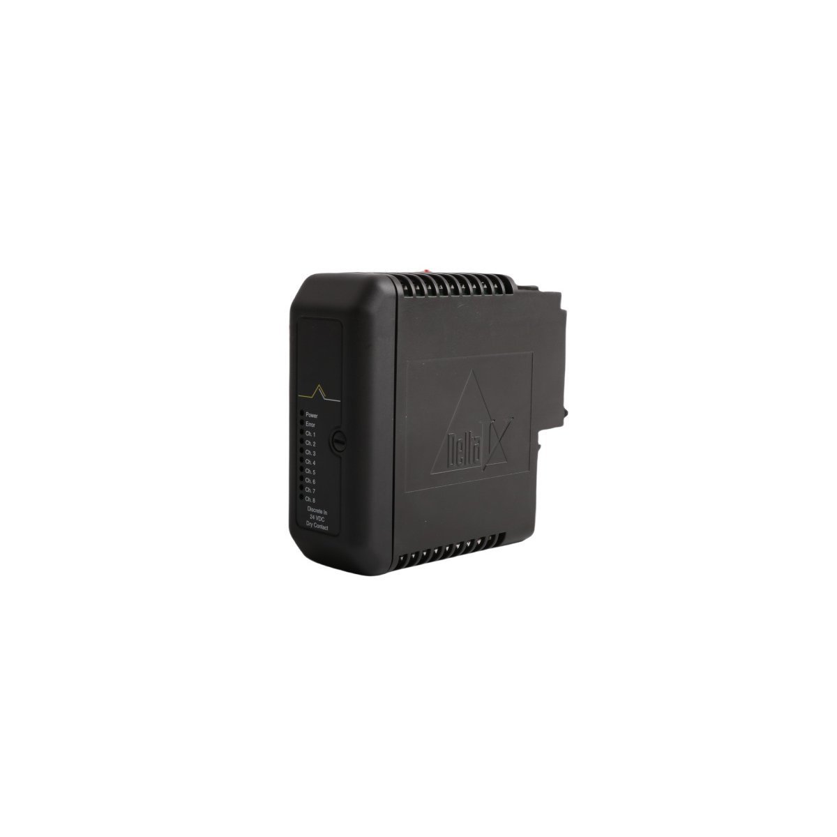
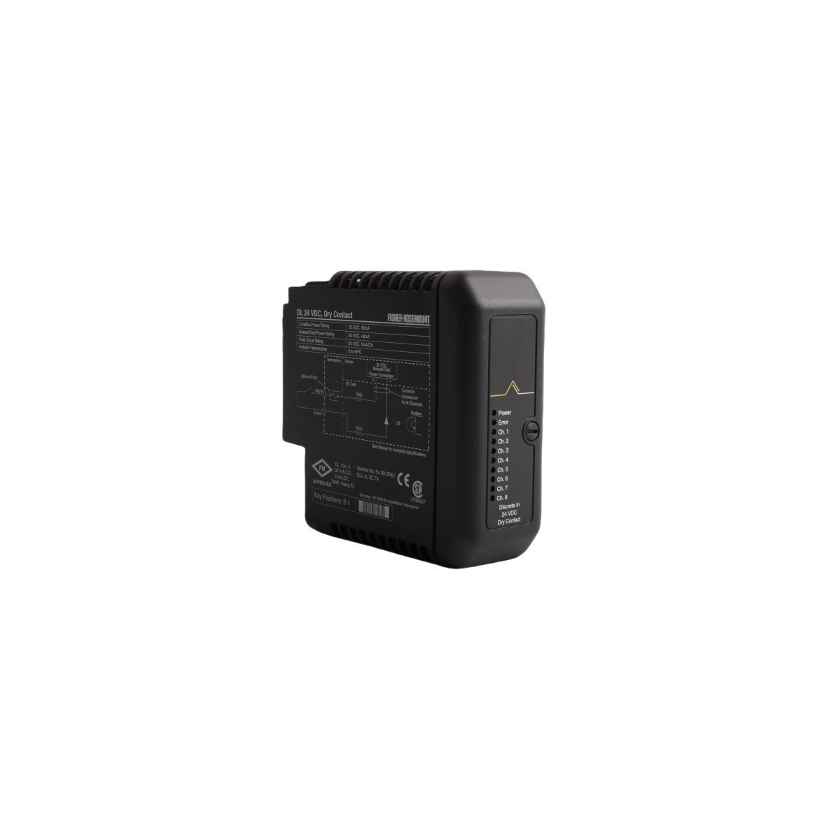
Secure the EMERSON KJ3001X1-BB1 12P0550X142 Dry Contact Module for your DeltaV SIS. Brand New, Original Stock, factory-direct spare ready for Global Shipping. Maximize your DCS runtime—Request an instant quote today.
The GE Fanuc IC200CHS022 is a 36-terminal, box-style I/O carrier for the VersaMax series. It supports high-density field wiring, DIN-rail mounting, and tool-free module replacement to maximize system uptime and reliability.
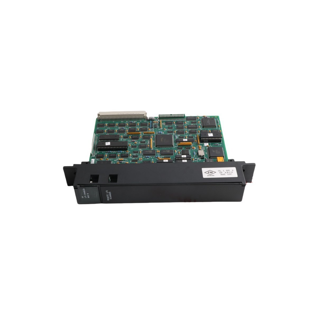
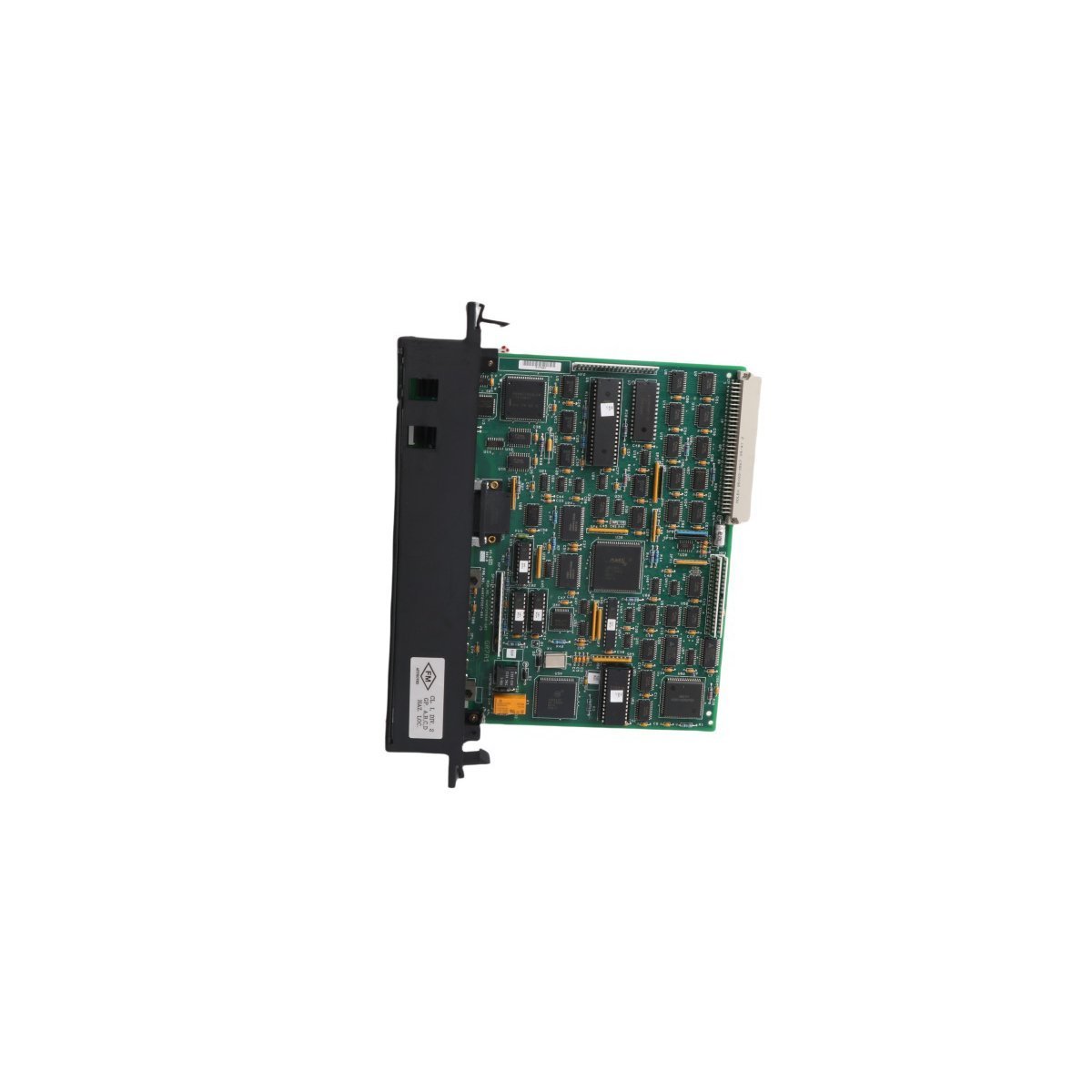
The GE Fanuc IC697BEM733 is a Series 90-70 Remote I/O Scanner module that manages distributed I/O up to 7,500 feet away. It supports 1,024 discrete points and 64 analog words, featuring RS-422/485 connectivity and Hand-held Monitor support for advanced industrial automation and long-distance control.
The GE Multilin UR6DV is a versatile Digital I/O module designed for the Universal Relay series. It features a compact 0.36kg design with integrated digital inputs and outputs for substation automation. This genuine GE component provides reliable status monitoring and control switching for DCS and protective relaying applications.
The Emerson KJ4001X1-BE1 (12P0818X072) provides a robust 8-wide I/O carrier solution for the DeltaV M-series subsystem. It features high-density module mounting, integrated power distribution, and reliable signal routing for advanced DCS industrial automation environments.
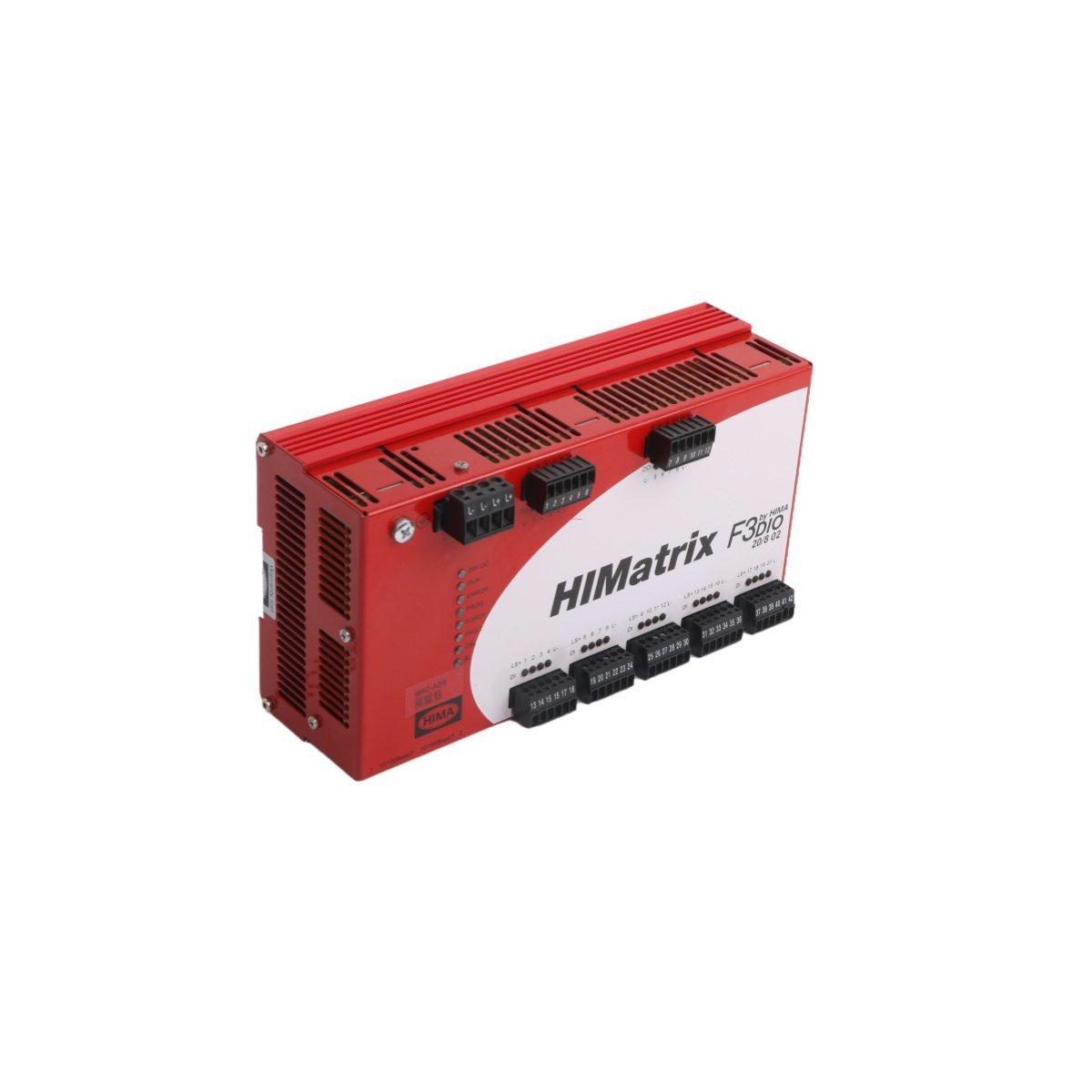
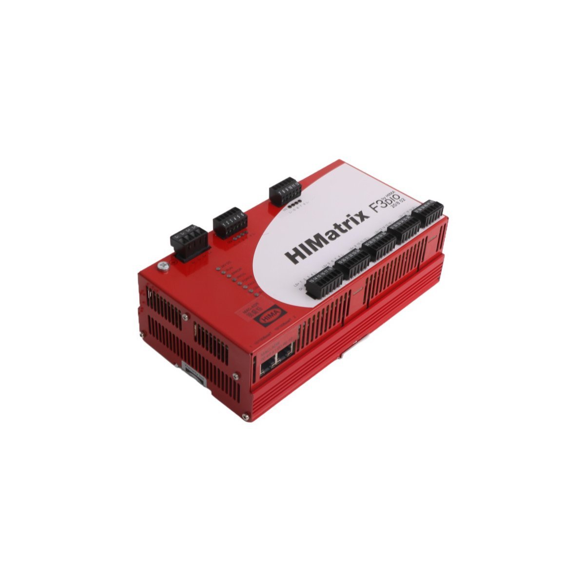
The HIMA HIMatrix F3DIO20/802 is a SIL 3-certified Remote I/O Module featuring 20 digital inputs and 8 digital outputs. Designed for decentralized safety-related automation, this module ensures high-speed data transmission over Ethernet with maximum fault tolerance. It provides a robust, German-engineered solution for emergency shutdown and process safety applications in harsh industrial environments.
The ICS Triplex T3491 is a high-performance Multiplexed I/O Module designed for the Regent Control System. It provides fault-tolerant analog signal processing and integrated diagnostics for safety-critical PLC applications. This brand-new, USA-made module features an 1.82 kg robust build and Ethernet router service capabilities to ensure seamless industrial automation connectivity.
The Emerson KJ3221X1-BA1 (12P2531X062) is a high-reliability DeltaV Redundant I/O Baseplate designed for Series 2 systems. It enables seamless module redundancy and hot-swappable maintenance for critical DCS applications in harsh industrial environments.
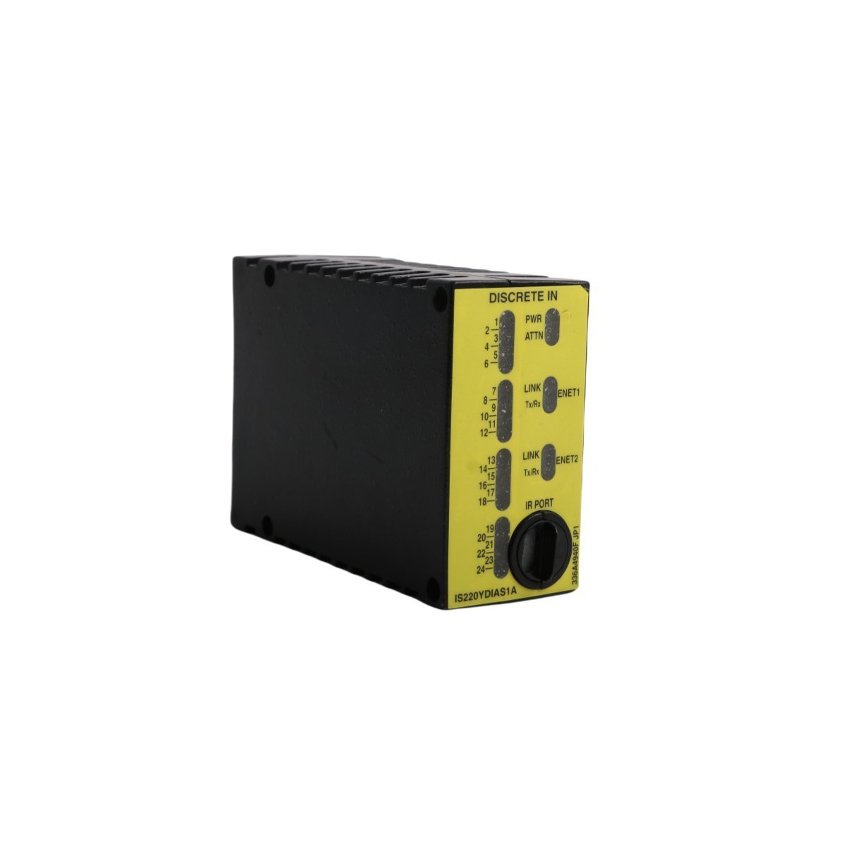
The GE IS220YPROS1A is a high-speed backup protection I/O module designed for the Mark VIe control system. It provides critical overspeed monitoring and emergency shutdown logic for turbines, featuring dual-port redundancy and TMR capabilities to ensure maximum power plant safety and reliability.
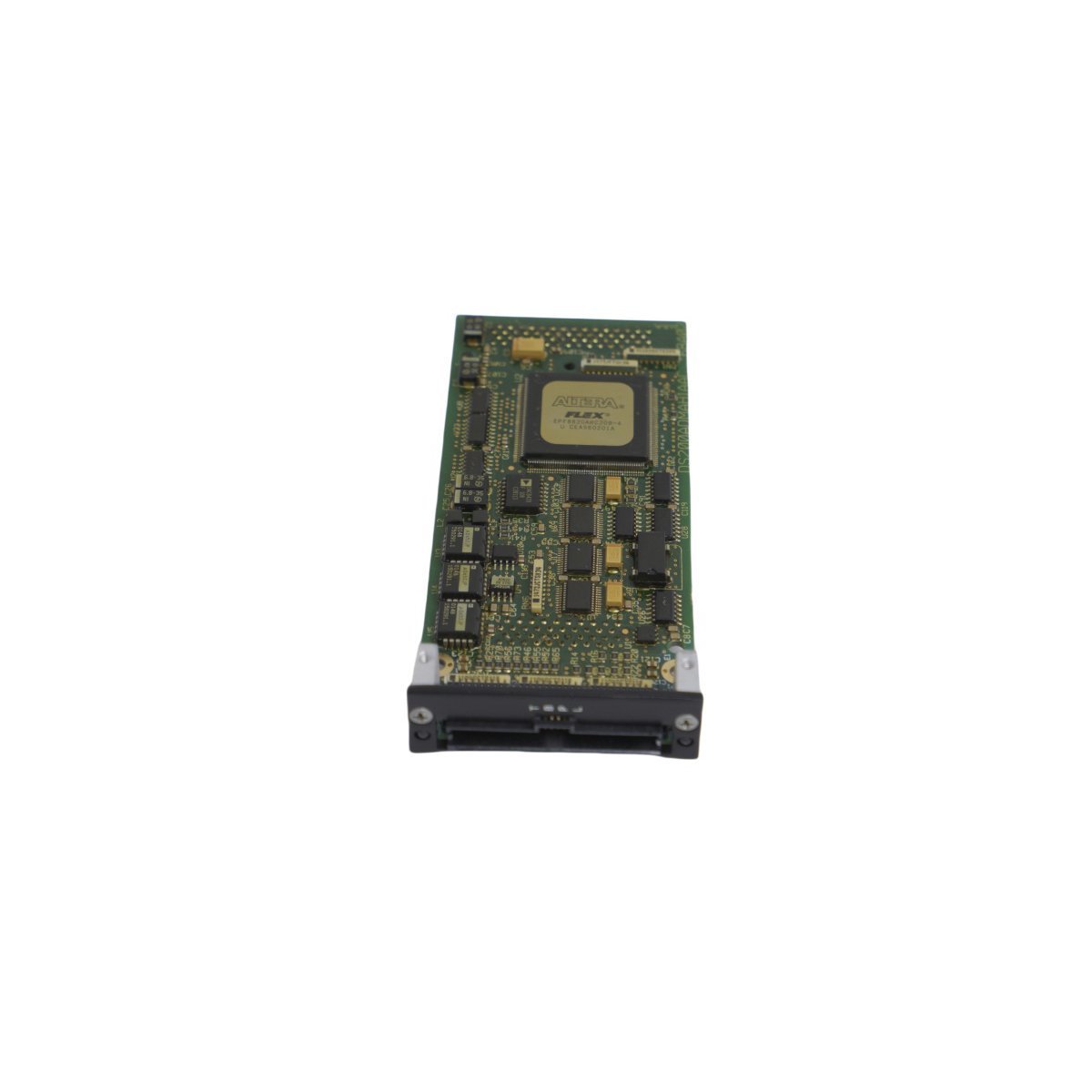
The General Electric DS6800CCID1D1D is a high-reliability I/O Interface Board for the Mark V Speedtronic system. It provides essential signal conditioning and high-speed data conversion, supporting both TMR and Simplex architectures in mission-critical turbine control applications.
The HIMA HIMatrix F3 DIO 16/8 01 is a SIL 3 certified safety digital I/O module featuring 16 inputs and 8 outputs.By leveraging safeethernet communication and dual-processor diagnostics, it provides high-speed, decentralized control and robust fault detection for mission-critical Safety Instrumented Systems (SIS)
We are committed to protecting your privacy. The information collected here is strictly used to provide the requested quotes, technical support, and relevant industrial automation solutions.