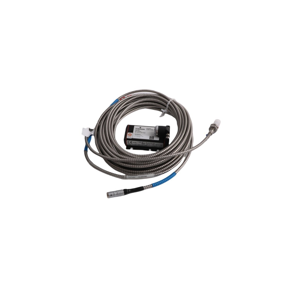
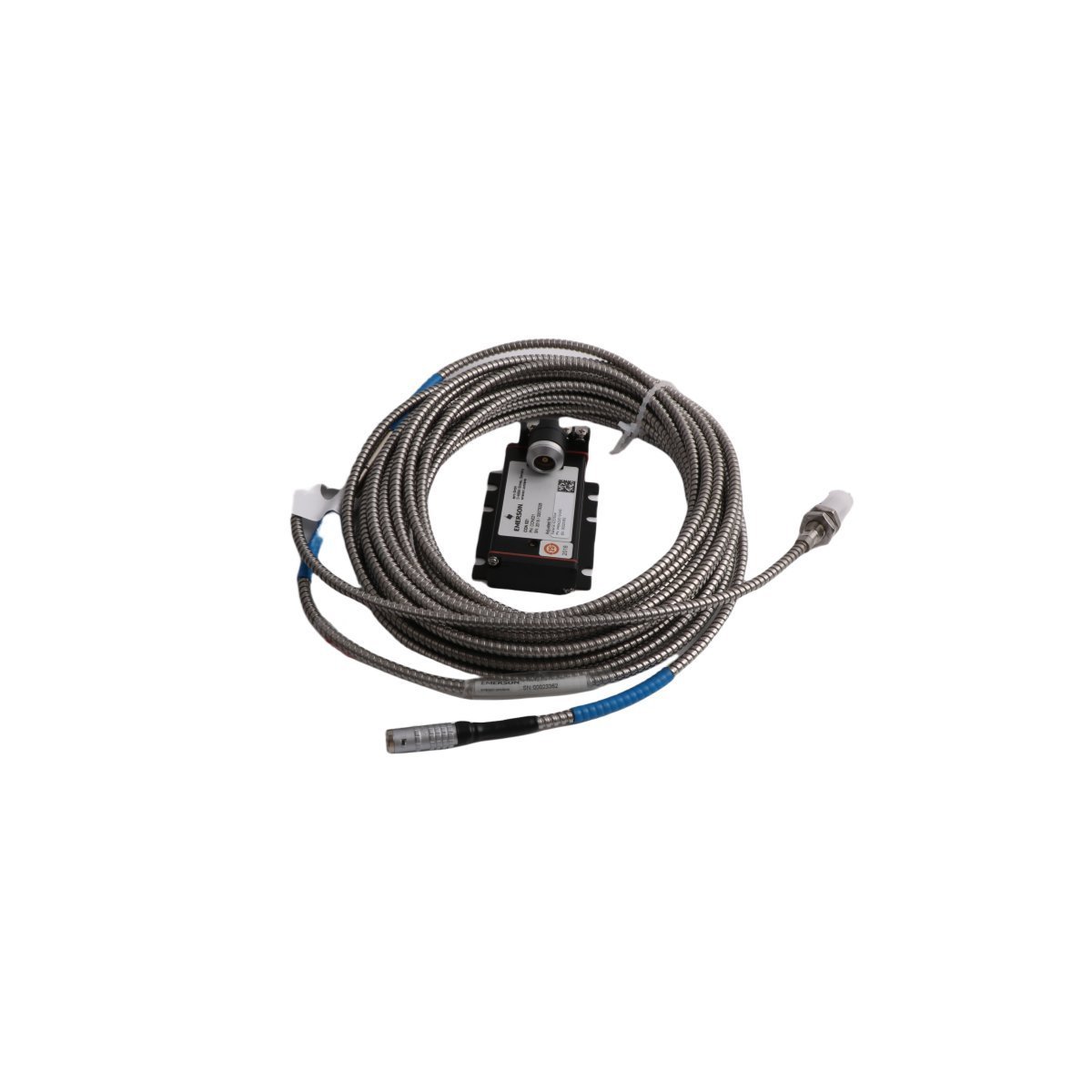
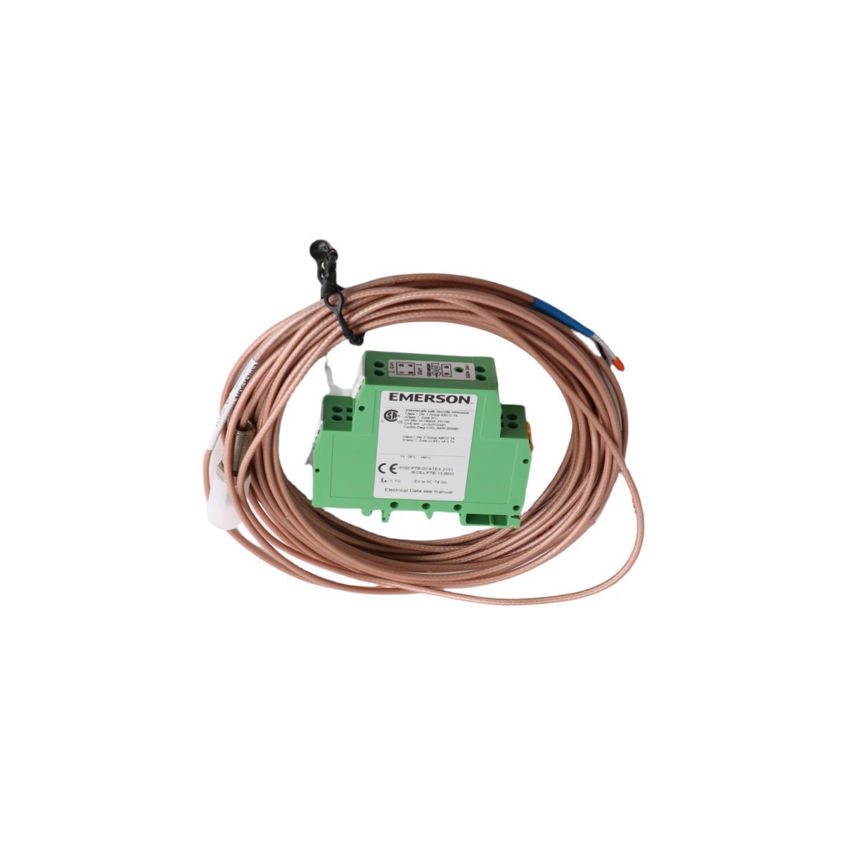
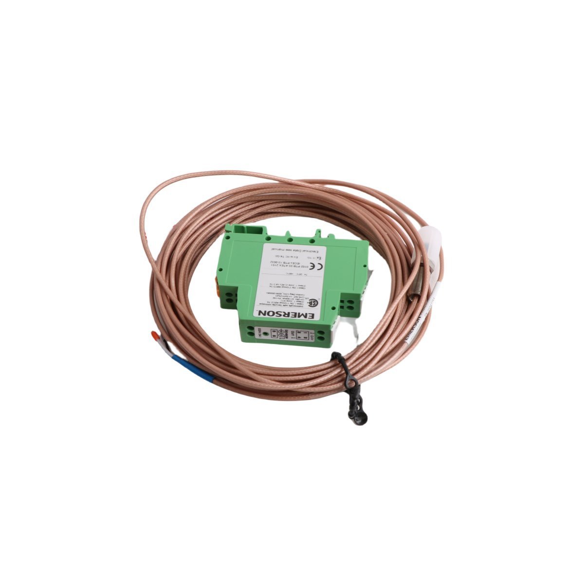
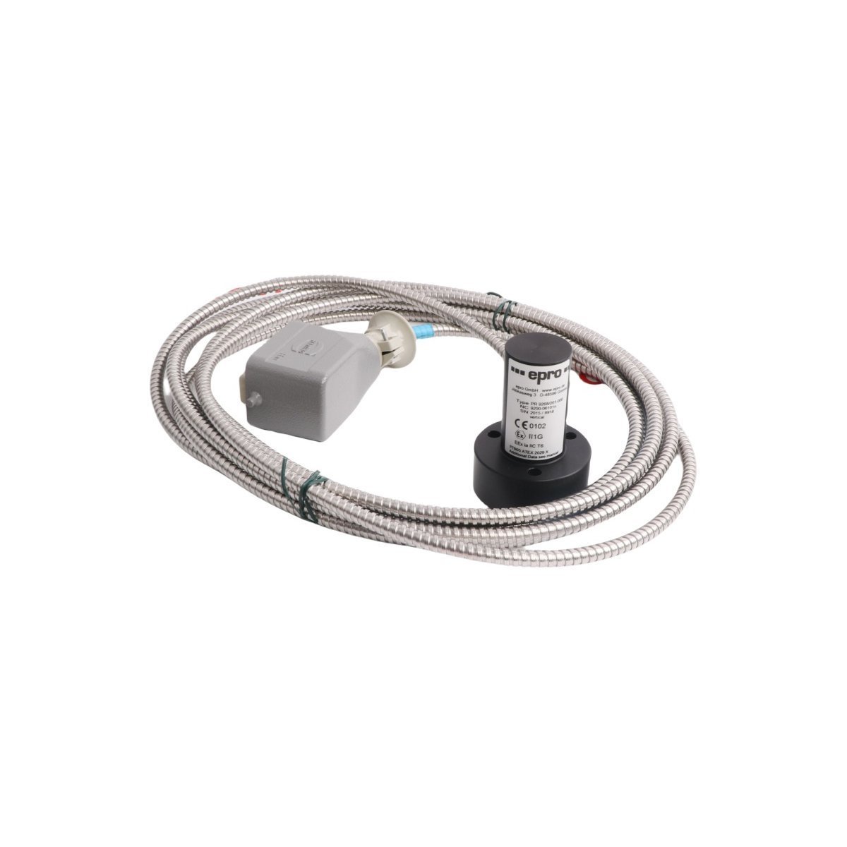
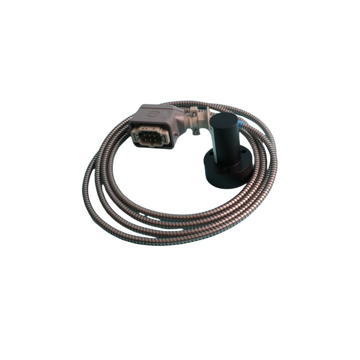
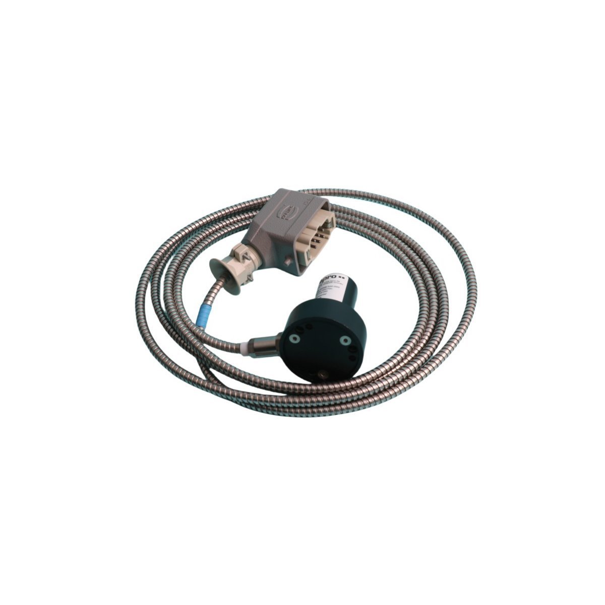
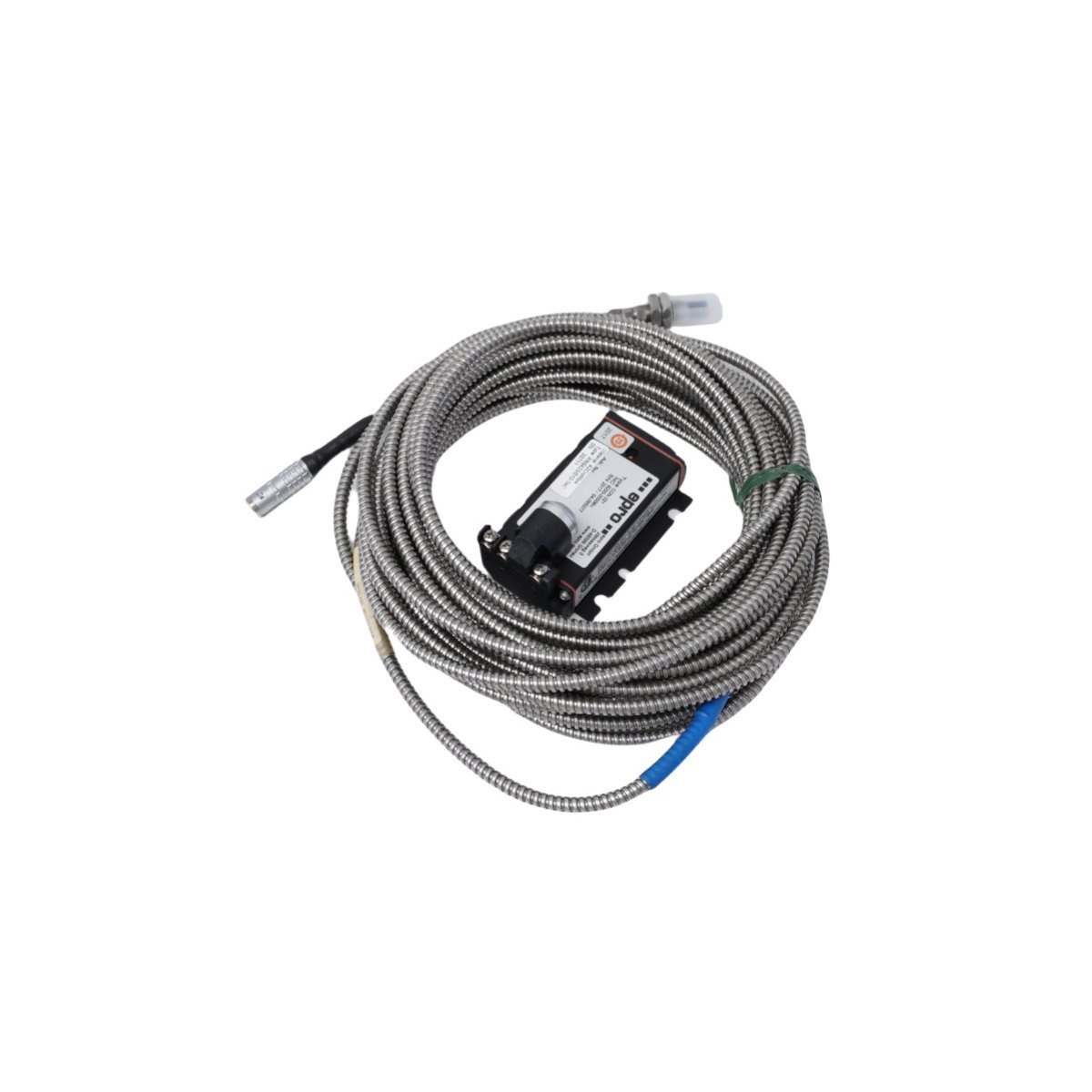
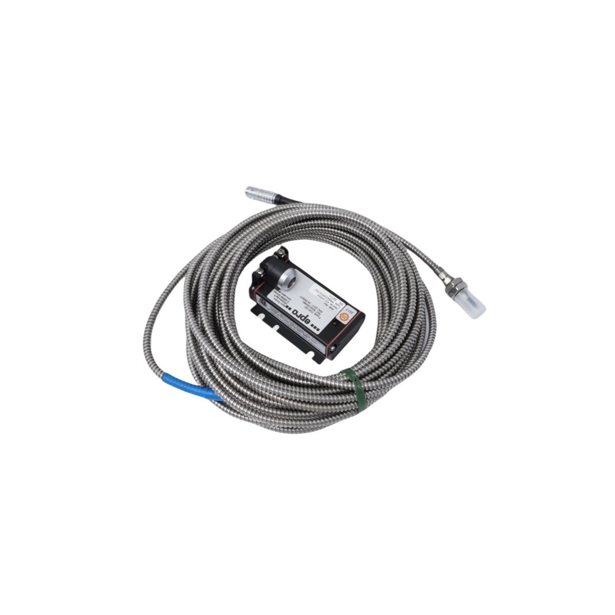
You are here:
SKU: PR6423/009-031 CON041

EMERSON PR6423/009-031 CON041 Eddy Current Signal Converter

The EMERSON PR6423/009-031 CON041 delivers stable eddy-current transformation for shaft dynamic tracking. Brand New, Original Stock, fully certified with Global Shipping. Minimize critical machine downtime—Request a quote now.

The EMERSON PR6423/009-031 CON041, also cataloged as the PR6423/009-031 Eddy Current Signal Converter, serves as the primary PR6423 Eddy Current Signal Converter utilized to execute mechanical monitoring tasks across EPRO and DeltaV distributed control system platforms. The device executes direct signal modification by processing low-level high-frequency inputs generated by non-contacting displacement sensors into standardized analog voltage or current outputs proportional to shaft dynamic metrics.

Hardware Specifications

ParameterSpecification
ModelPR6423/009-031 CON041
BrandEMERSON
OriginUSA
Weight0.28 kg
Dimensions20.0 cm x 20.0 cm x 2.0 cm
Operating Temp-35 to 85 deg C
Power Consumption24 VDC nominal supply input
Module TypeEddy Current Signal Converter
SystemDCS / TSI Machinery Protection System
HS CODE8537101190
Discontinued DateDec 31, 2018
Communication ServiceDirect analog transmission / carrier path

Turbomachinery Monitoring & TSI Characteristics

This EPRO series instrument executes critical physical tracking within turbo-machinery protection circuits by performing precise eddy-current probe scaling. The analog converter circuitry enforces strict gap voltage validation targeting specific nominal limits, converting micro-displacement variations from proximity sensors into linear execution loops. Integrated cross-talk suppression paths isolate adjacent high-frequency sensor streams, preventing interference and maintaining high accuracy during high-velocity rotor dynamics assessments and absolute shaft vibration tracking.

Frequently Asked Questions

Q: How is eddy-current probe scaling adjusted for specific shaft target materials?

A: Calibration parameters are set internally via factory hardware grouping. Alteration of targeted electrical characteristics or sensor cable length variations requires dedicated readjustment of the terminal scaling configuration.

Q: What is the primary function of the gap voltage validation circuit?

A: The validation circuit continually samples the static DC bias voltage across the sensing loop. Deviations outside specified limits signify loop failure, triggering sensor fault indicators across the host system.


Field Installation Guidelines

  • Mount the converter enclosure directly within a shielded field housing to prevent electromagnetic radiation from corrupting low-amplitude sensor feedback loops.
  • Enforce strict isolation bounds between the high-frequency sensor extension cables and general plant high-voltage power conduits.
  • Ground the outer coax shields strictly at a single termination boundary to eliminate common-mode ground loops that degrade measurement precision.
  • Confirm that the driver module is mounted onto a securely grounded DIN-rail structure to permit sufficient passive dissipation.