Sale!
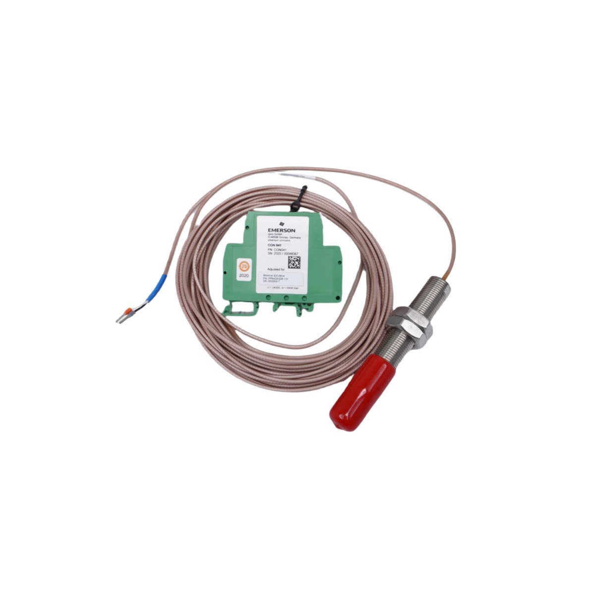
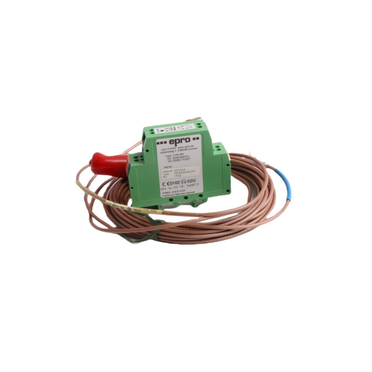
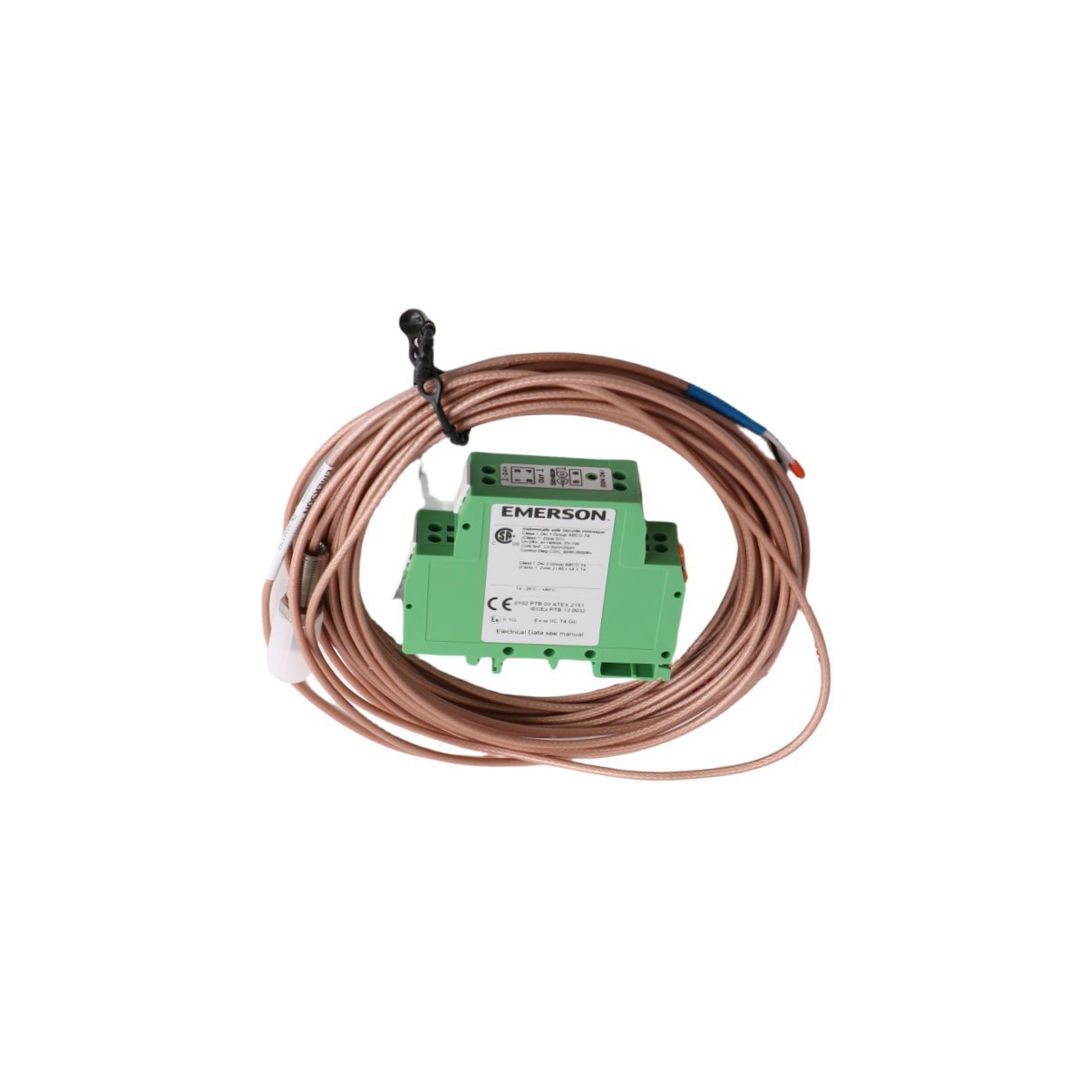
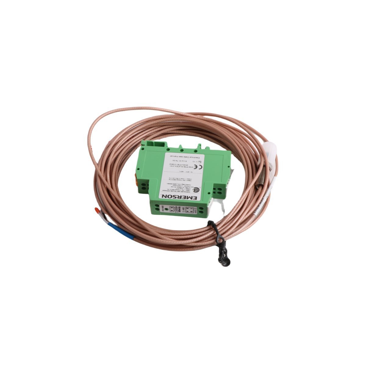
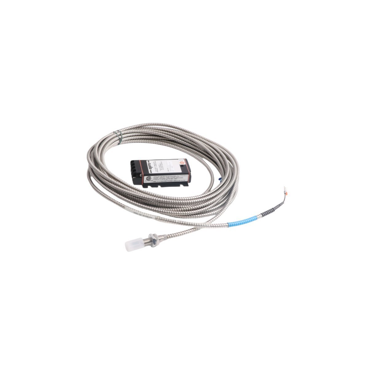
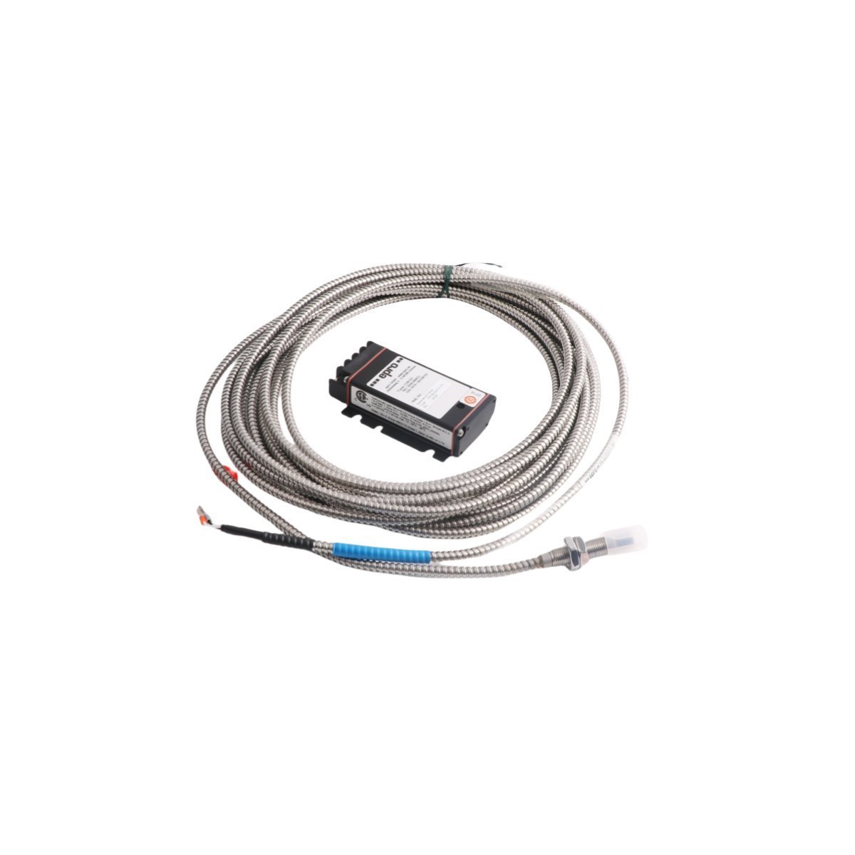
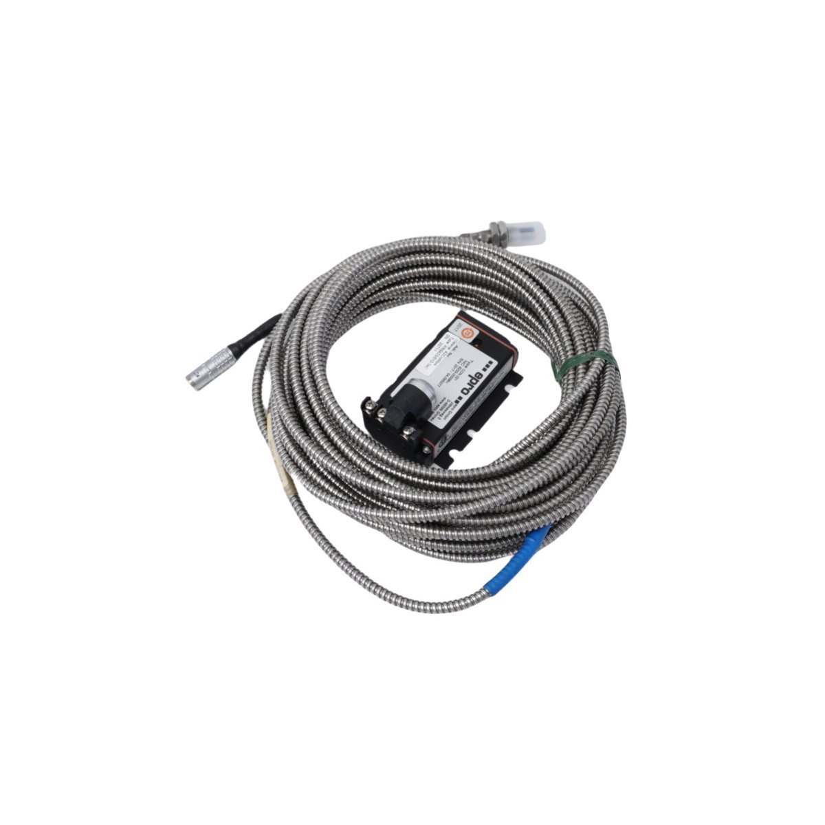
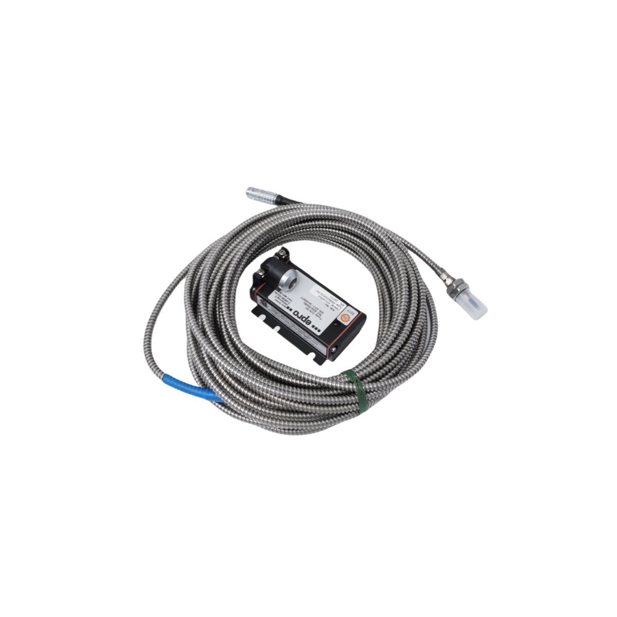
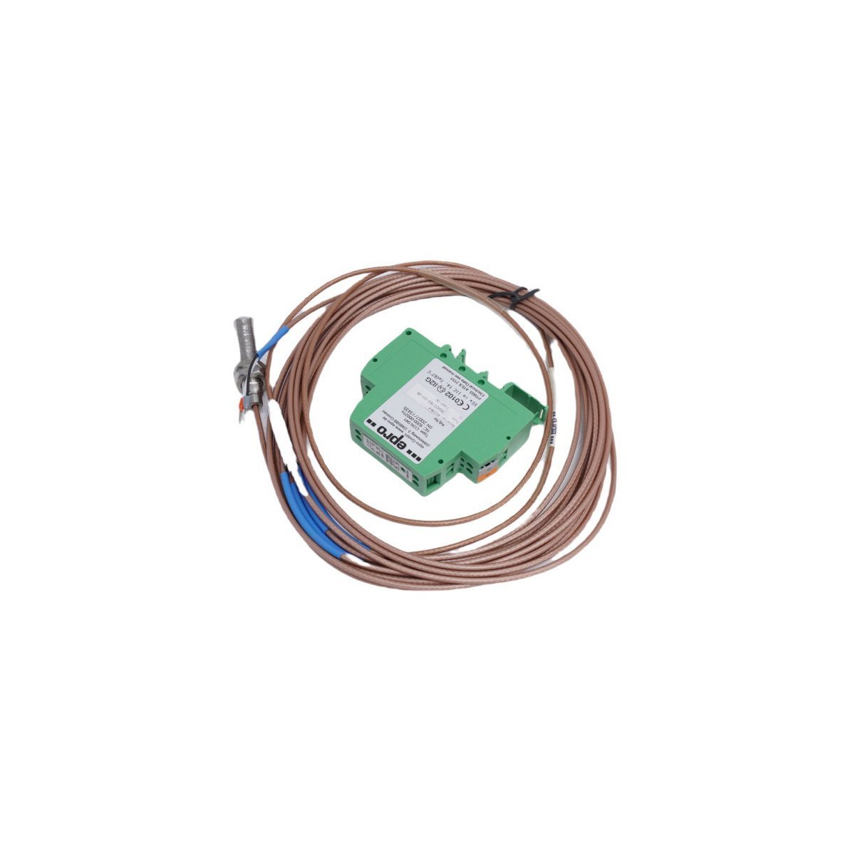
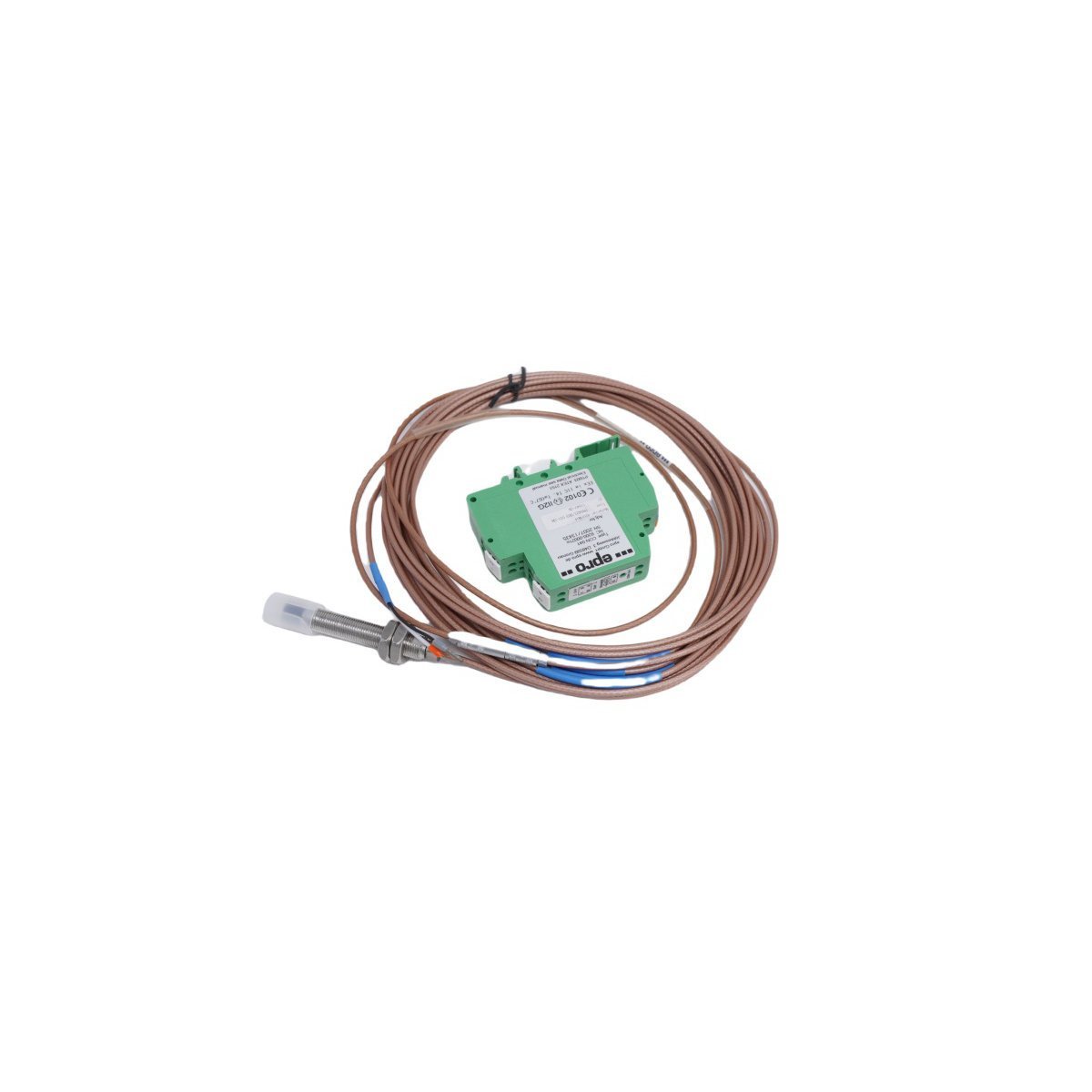
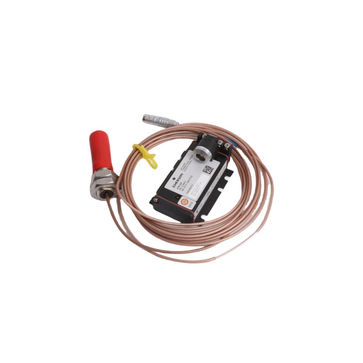
Emerson PR6424/002-031 CON041 Eddy Current Sensor
Configured for high-precision displacement monitoring in rotating machinery, the Emerson PR6424/002-031 CON041 (PR6424/002-031 Eddy Current Sensor) provides direct electrical execution of shaft vibration and position feedback.
Hardware Specifications
| Parameter | Specification |
|---|---|
| Model | PR6424/002-031 CON041 |
| Brand | Emerson |
| Origin | USA |
| Weight | 0.34 kg |
| Dimensions | 17 x 14 x 3 cm |
| Operating Temp | Standard Industrial Specification |
| Power Consumption | System-Dependent |
| System | DCS (EPRO) |
Mechanical Monitoring & TSI Characteristics
The module utilizes eddy-current probe scaling to translate proximity data into linear voltage outputs. To maintain measurement accuracy, technicians must perform gap voltage validation, targeting a -10 VDC baseline for optimal performance. Furthermore, because rotating machinery exhibits complex rotor dynamics, proper installation is necessary to ensure signal integrity. In addition to this, the system incorporates cross-talk suppression techniques. Consequently, this prevents noise interference between adjacent probes in multi-channel monitoring arrays.Frequently Asked Questions
Q: What is the primary function of the -10 VDC gap voltage target?A: The -10 VDC target serves as the nominal midpoint for the sensor's linear measurement range. Therefore, adjusting the probe gap to this value ensures that both positive and negative displacement fluctuations are captured without signal clipping.Q: How can cross-talk be effectively mitigated during installation?A: You must maintain the specified physical separation between adjacent probe tips. Moreover, you should route signal cables through individual shielded conduits to prevent electromagnetic induction from nearby components.Field Installation Guidelines
- Mounting Orientation: You must secure the probe in a rigid, non-conductive bracket to avoid parasitic current loops.
- Calibration Verification: Initially, you must verify the static gap distance using a feeler gauge while the machine is at standstill. Subsequently, confirm the output voltage reaches the -10 VDC target prior to commissioning.
- Shielding and Grounding: You must ensure the coaxial cable shield is terminated at a single-point instrumentation ground. This prevents ground loops, which are a common source of signal noise.
- Wiring Requirements: Finally, you must keep all signal wiring isolated from high-voltage AC lines. Following this practice reduces the likelihood of inductive coupling, which can otherwise compromise the integrity of the vibration data.