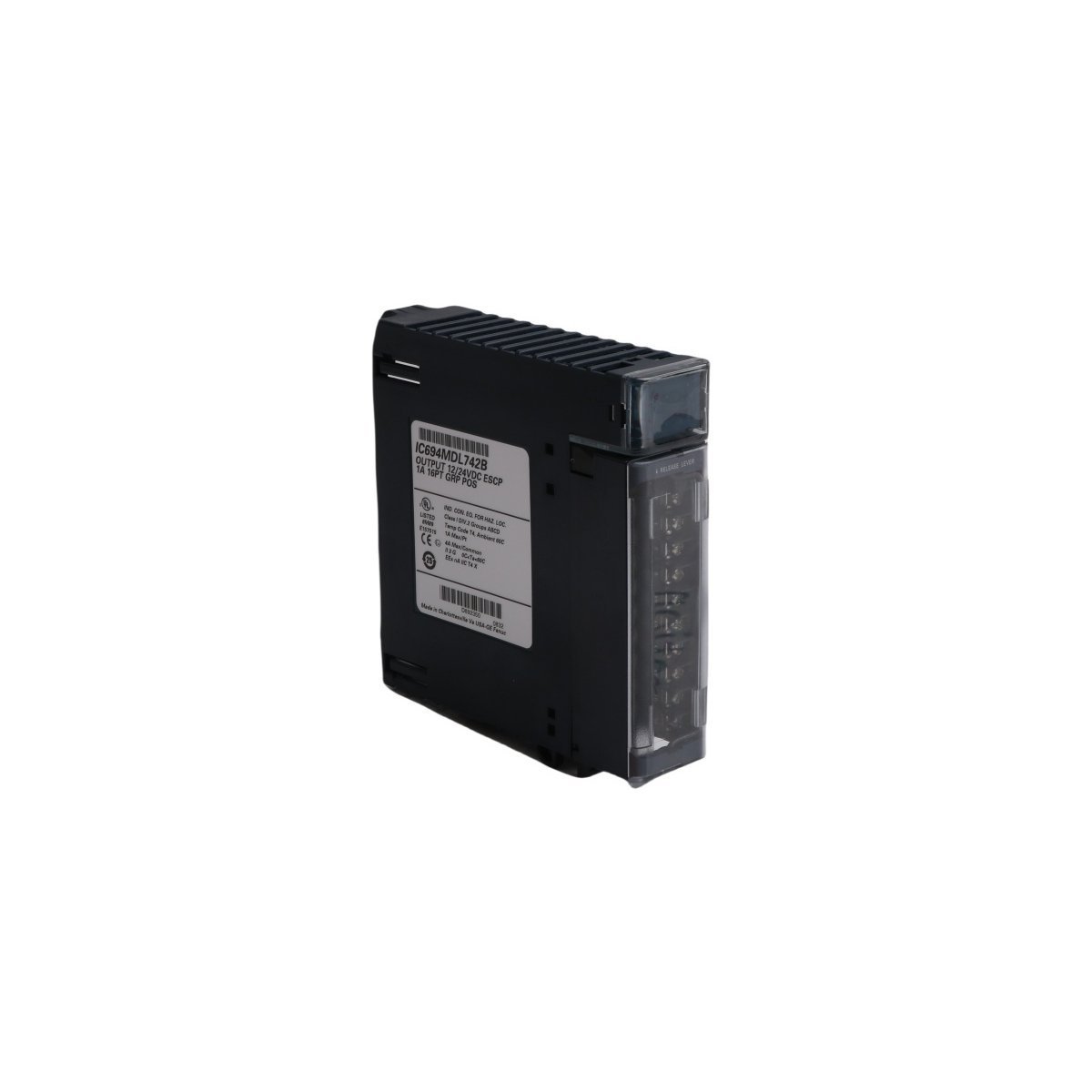
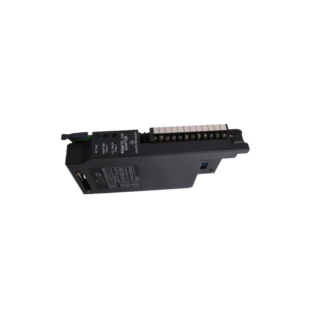
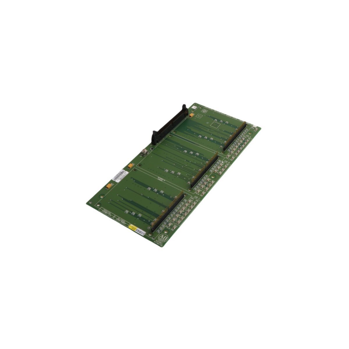
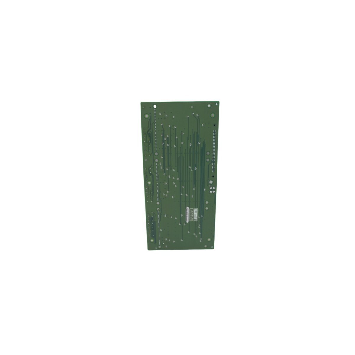
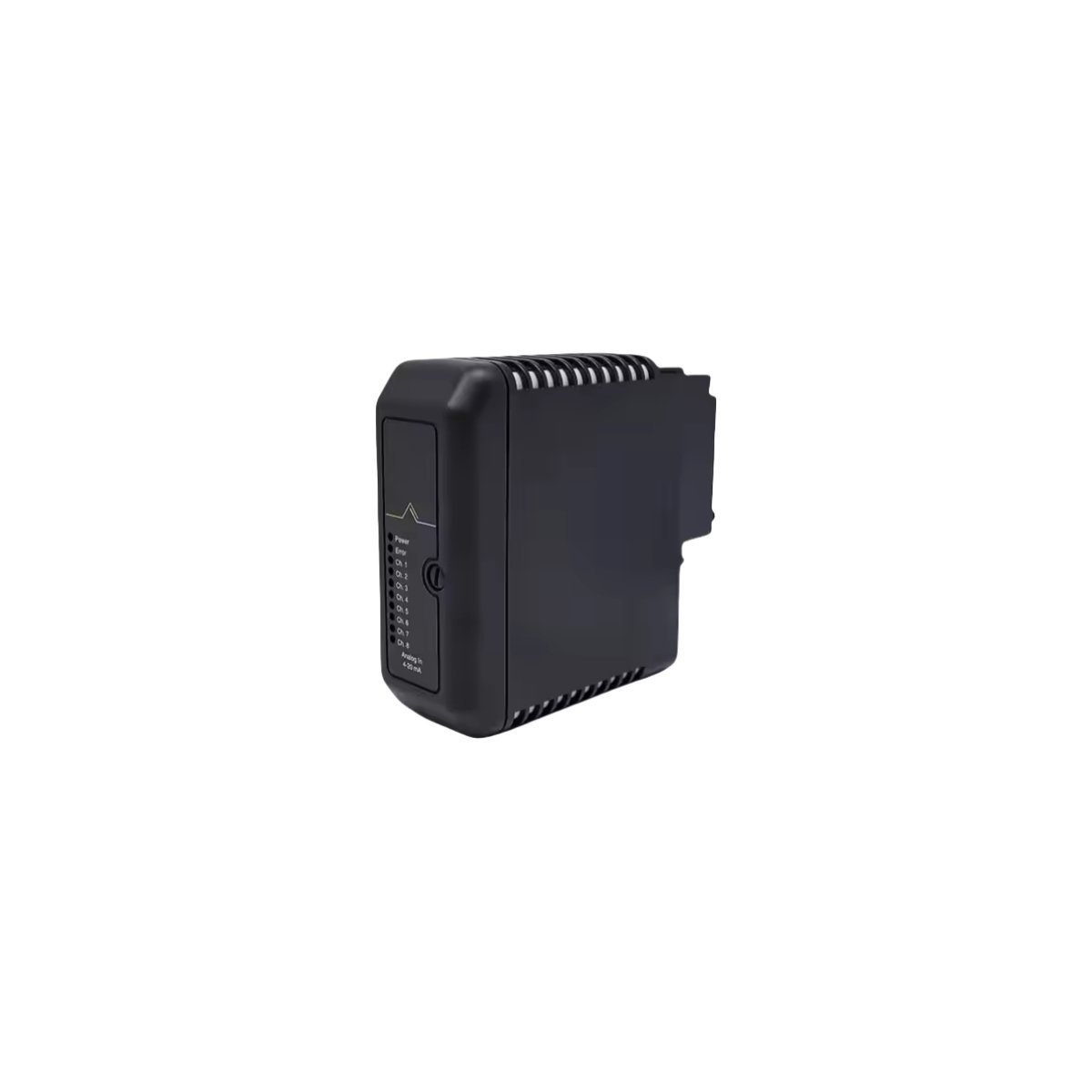
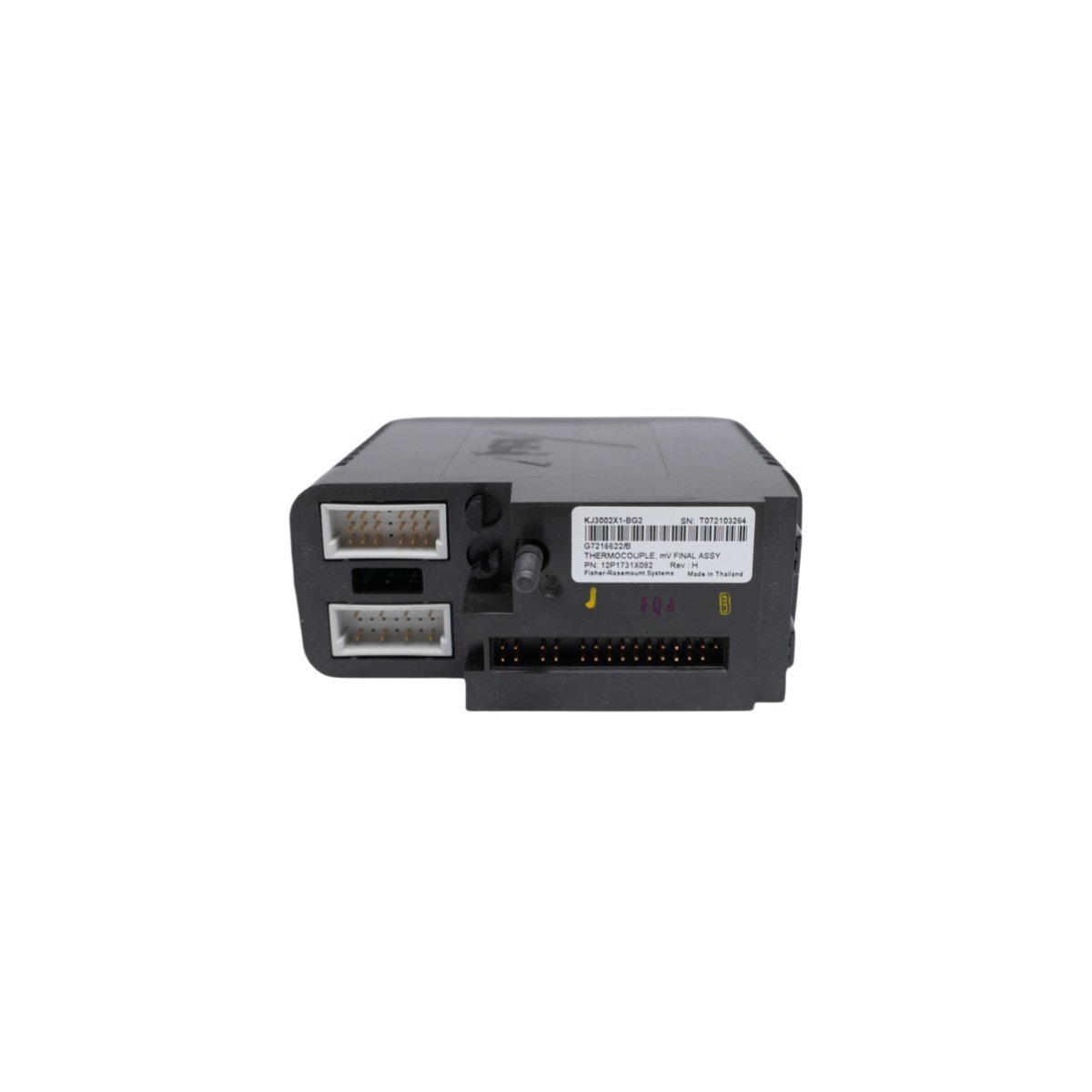
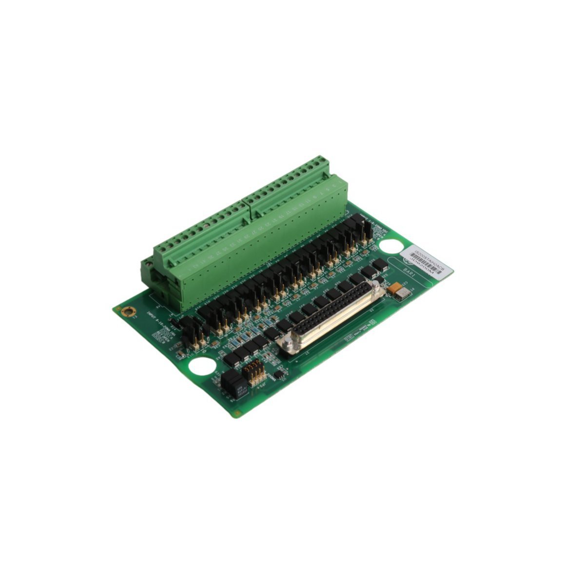
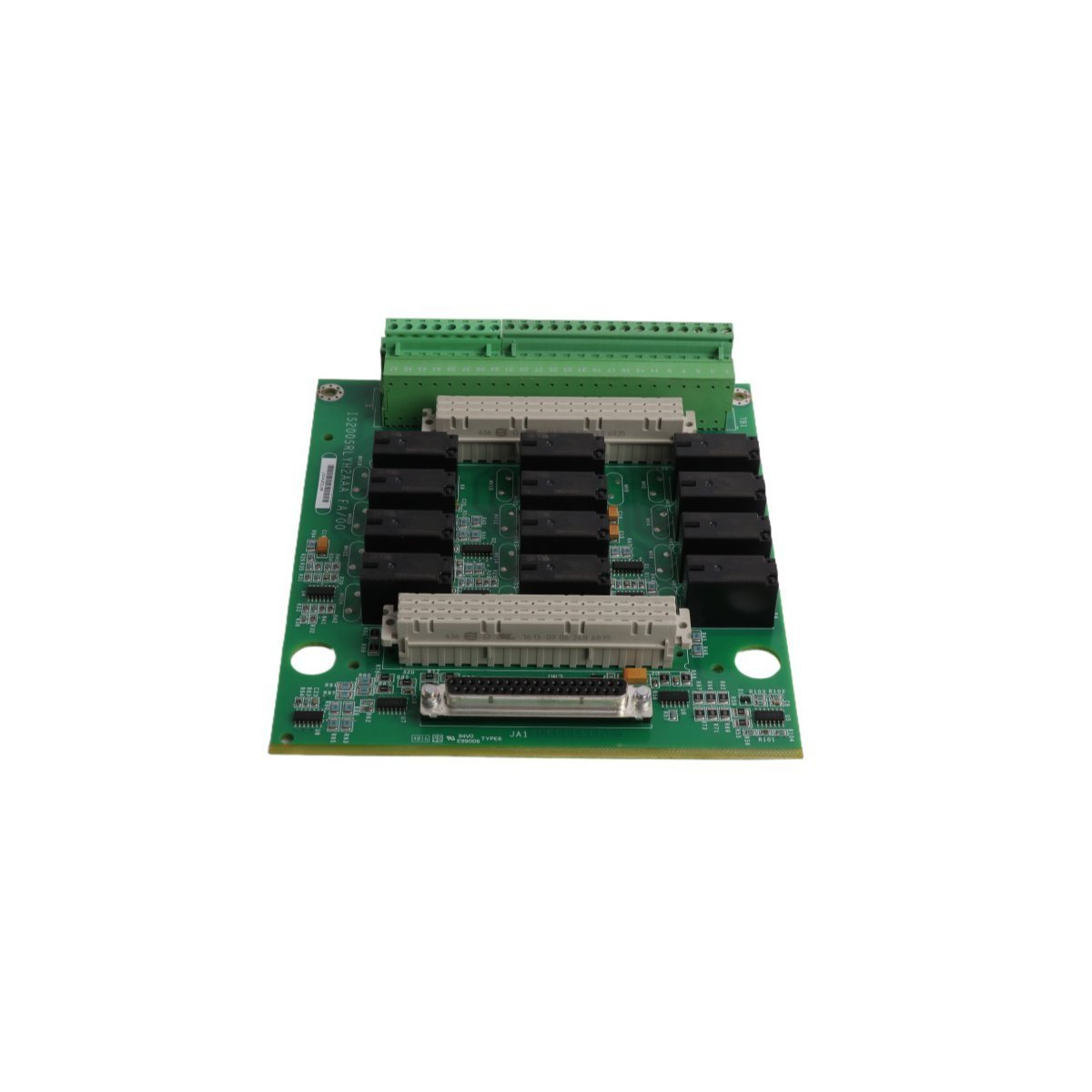
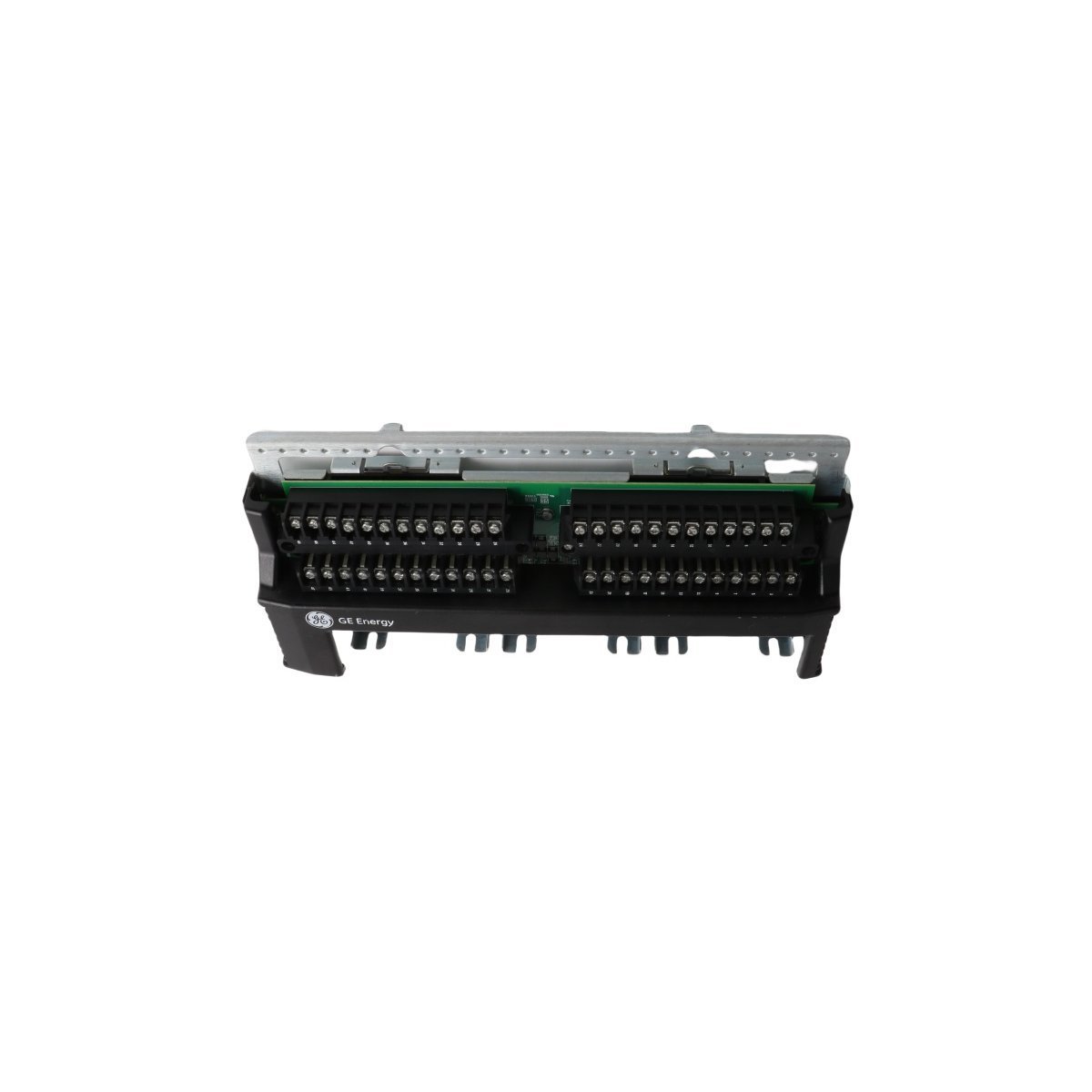
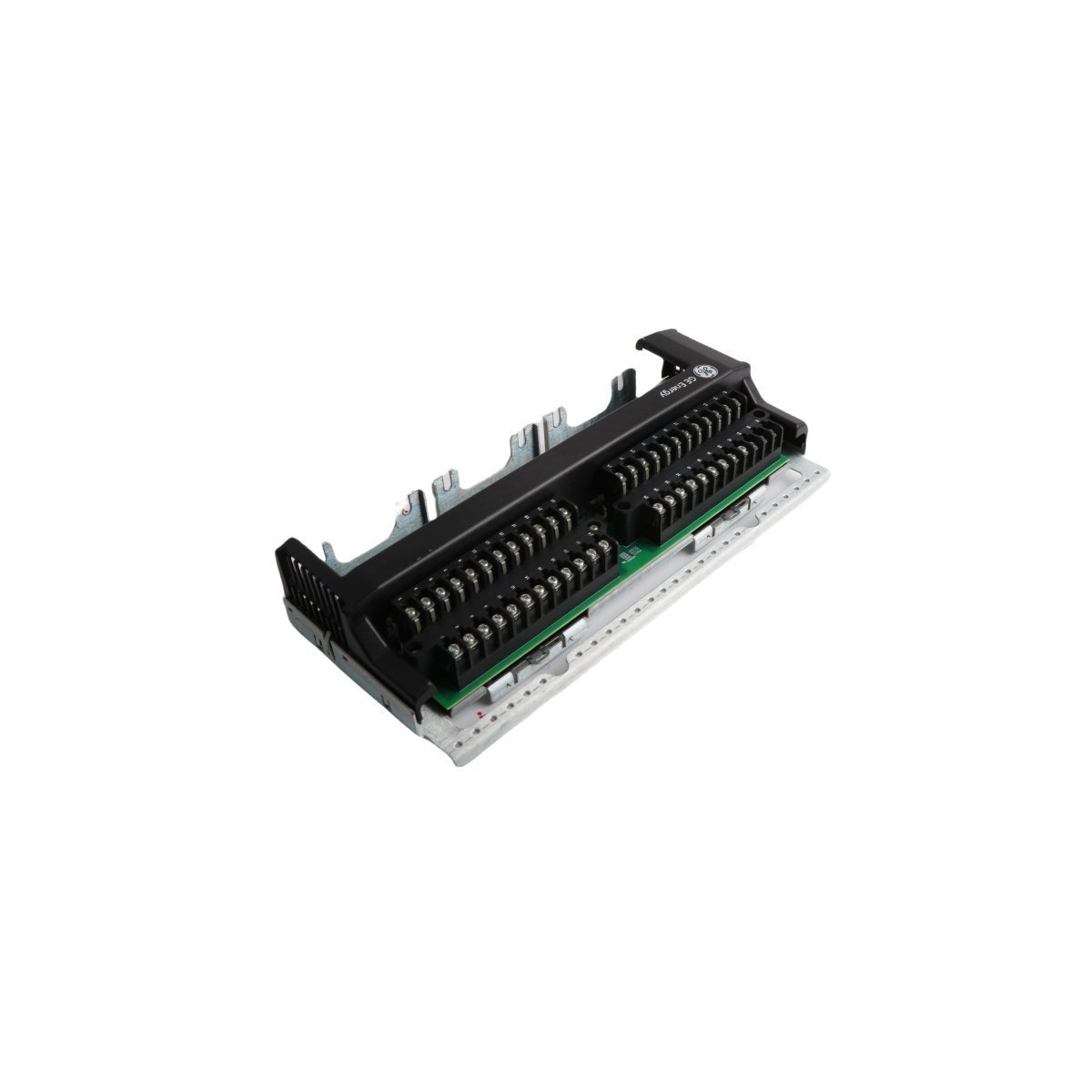
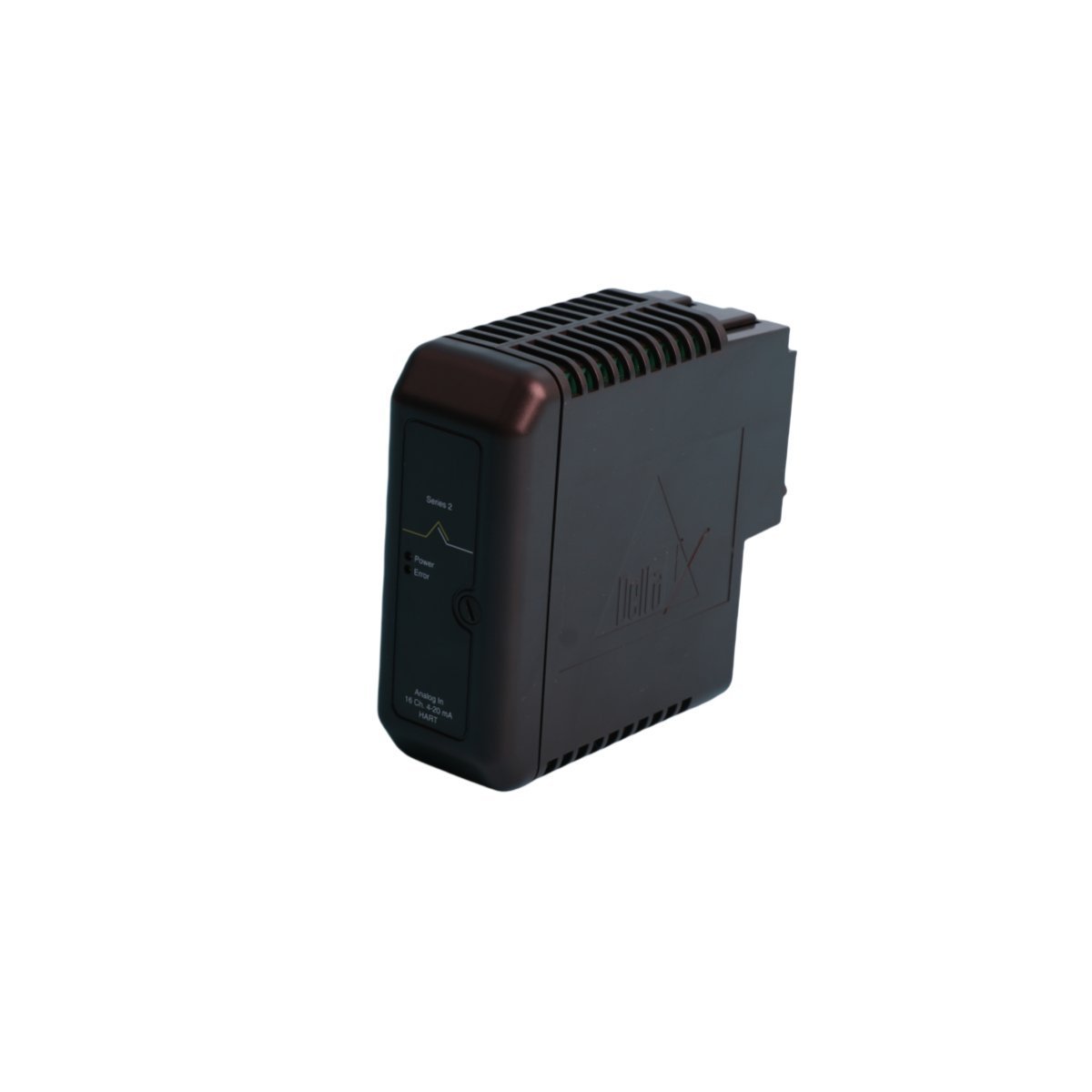
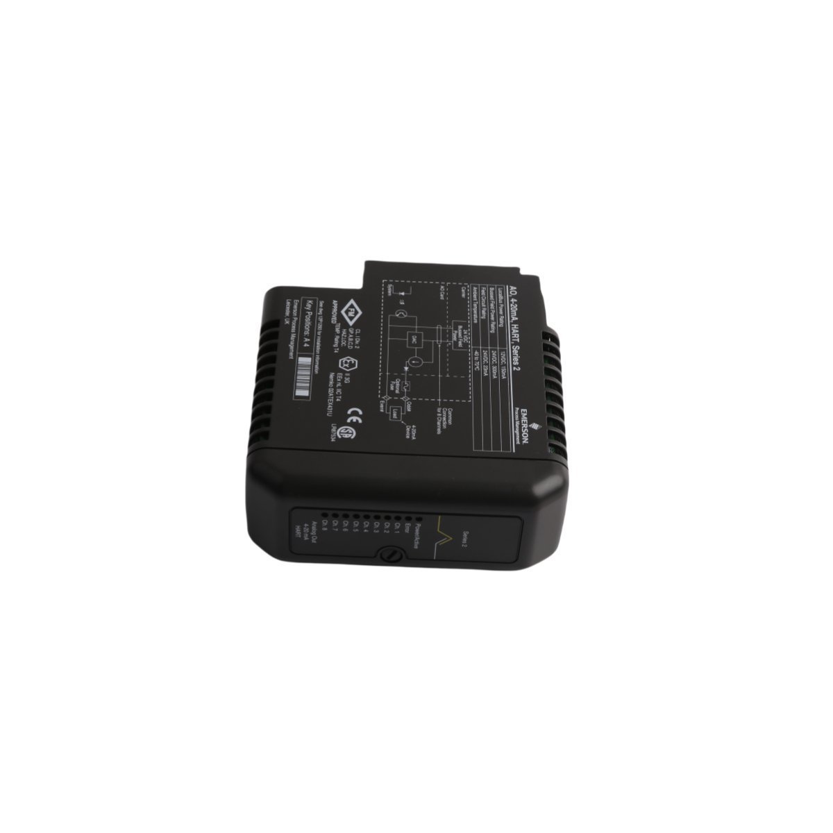
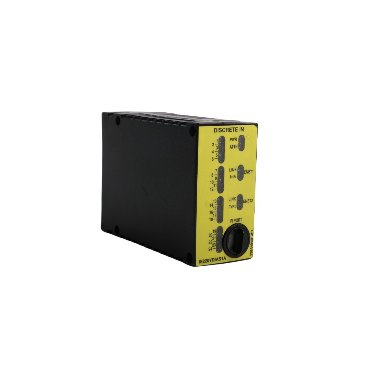
Emerson KJ2201X1-JA1 12P3323X022 SLS Redundant Terminal Block
Suffix Breakdown & Model Matrix
| Model | Description |
|---|---|
| KJ2201X1-JA1 | DeltaV SIS SLS Redundant termination interface |
| 12P3323X022 | Internal Emerson factory manufacturing reference code |
Hardware Specifications
| Parameter | Specification |
|---|---|
| Model | KJ2201X1-JA1 |
| Brand | Emerson |
| Origin | USA |
| Weight | 0.28 kg |
| Dimensions | 16.6 x 8.8 x 5.2 cm |
| Operating Temp | Standard industrial range |
| Power Consumption | Passive component |
| System Compatibility | DeltaV SIS |
Process Control & Connectivity
The KJ2201X1-JA1 functions as a passive interconnect interface within the DeltaV SIS architecture and facilitates direct field-to-I/O card connectivity. This terminal block secures redundant field signal connections and ensures consistent electrical continuity for critical safety loops. Field engineers must follow DeltaV backplane wiring standards to maintain signal integrity and prevent impedance mismatches throughout the safety control loop. The design accommodates high-density terminal mounting and provides a structured physical path for signals requiring 4-20 mA HART loop protocol connectivity, which standard process instrumentation demands.Frequently Asked Questions
Q: Does the KJ2201X1-JA1 require external power for internal switching?A: No, this unit is a passive termination component. It relies on the connected DeltaV SIS I/O card for logic execution and loop power distribution.Q: How does this terminal block support redundant system configurations?A: The hardware architecture provides dual-path termination points, allowing the SIS controller to monitor and execute fail-safe state transitions across redundant signal channels without hardware reconfiguration.Field Installation Guidelines
- Secure the terminal block onto the specified DIN-rail mounting position within the DeltaV SIS carrier.
- Tighten all terminal screws to the manufacturer-specified torque limits to prevent intermittent contact resistance under vibration.
- Terminate field wiring according to the loop diagram to ensure correct channel mapping.
- Route shielded cables through designated cable trays to minimize electromagnetic interference (EMI) impact on analog signal precision.
- Verify electrical continuity across the redundant paths using a calibrated multimeter before energizing the I/O loop.