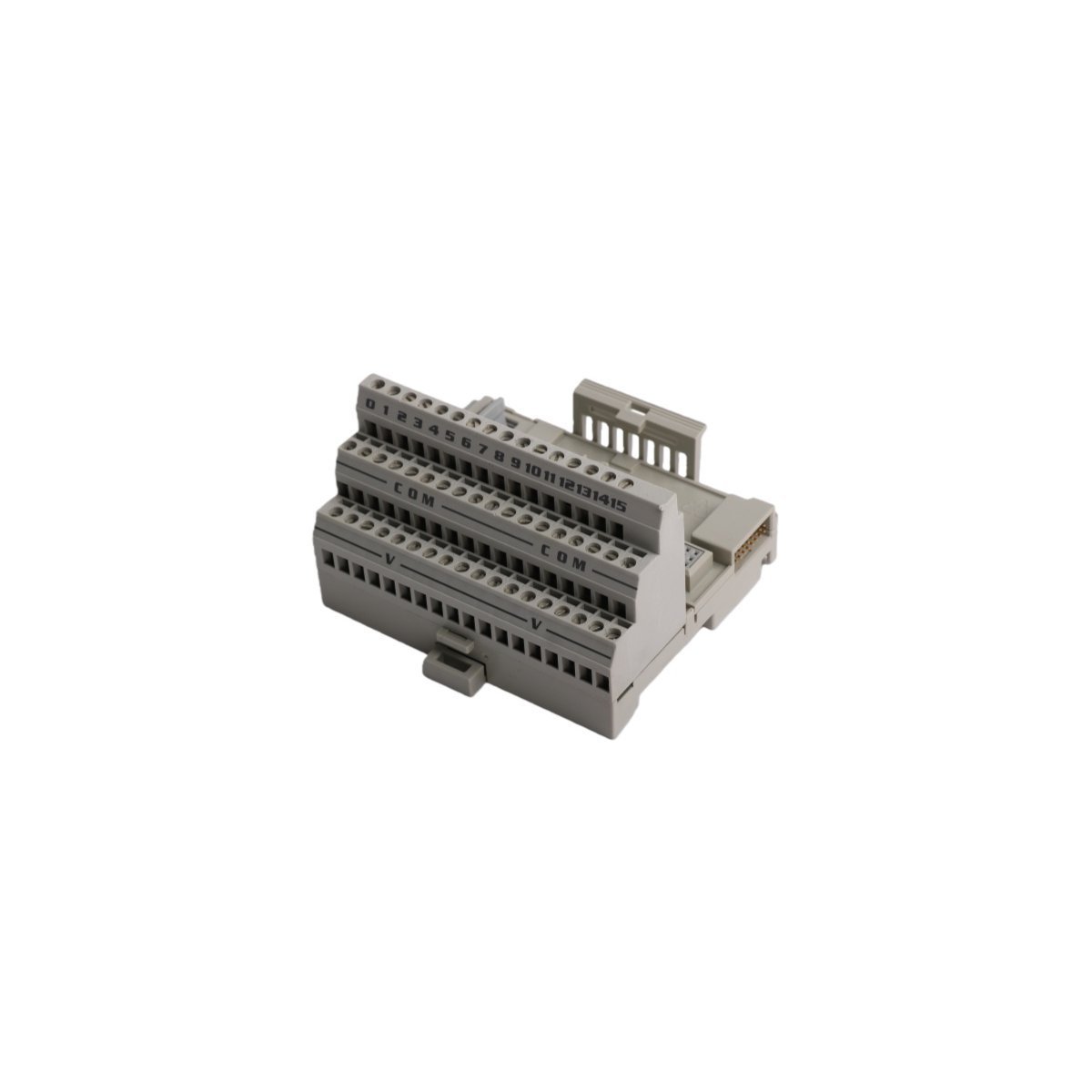
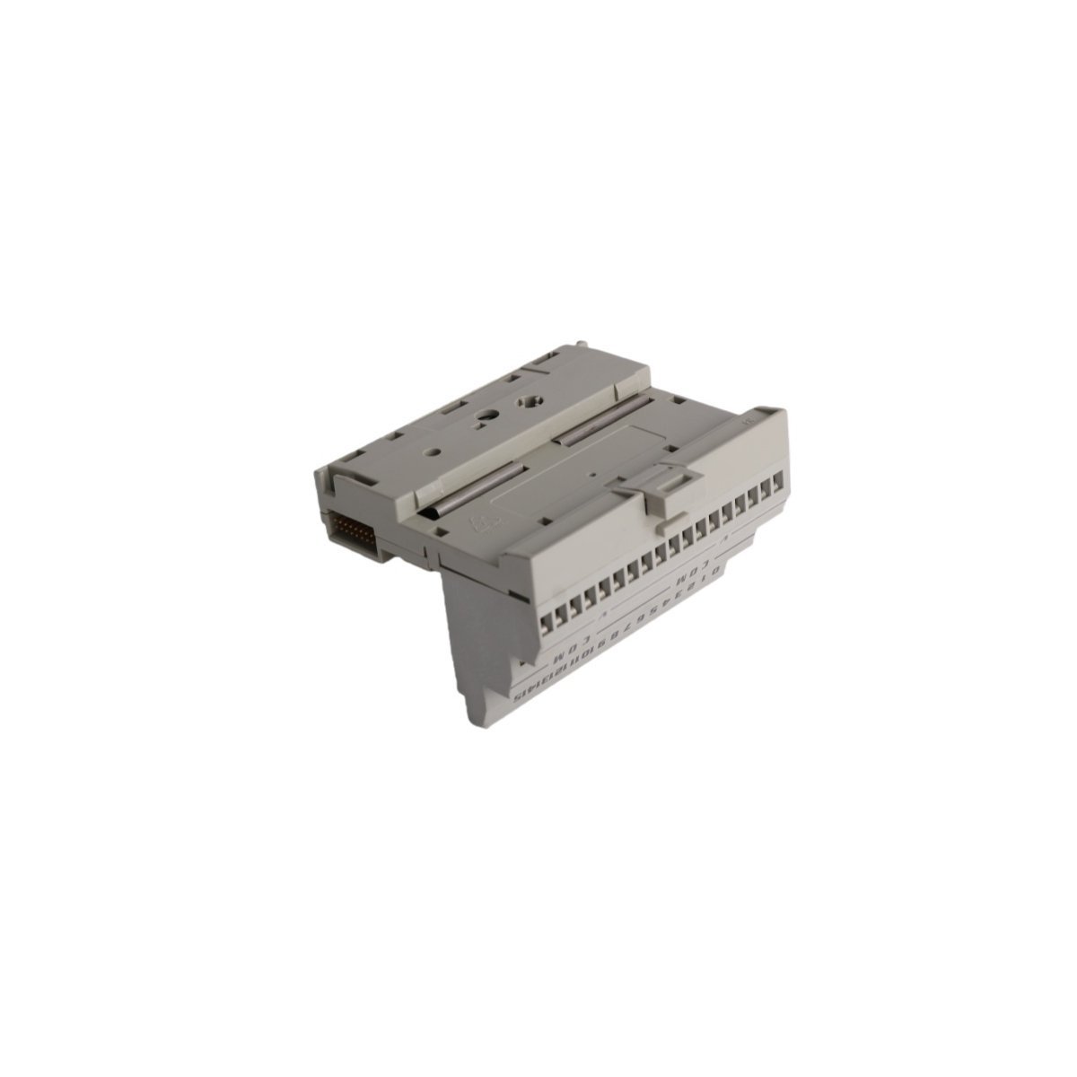
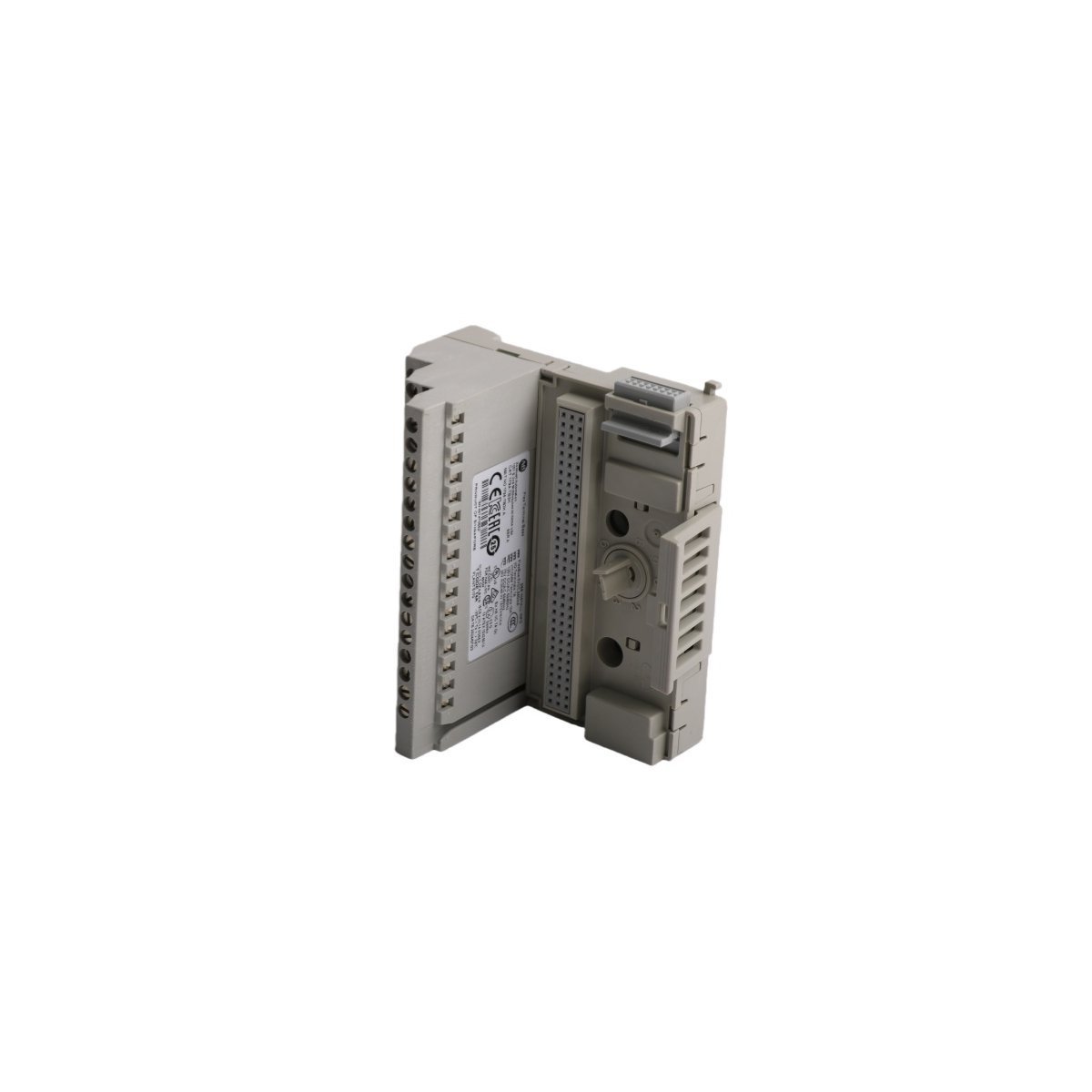
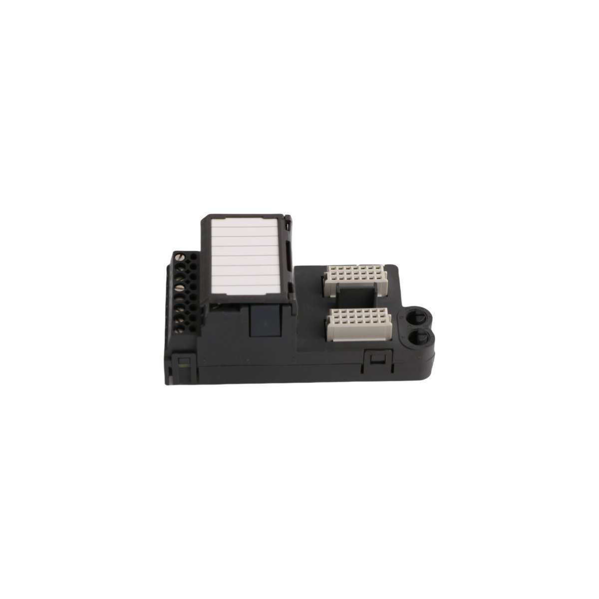
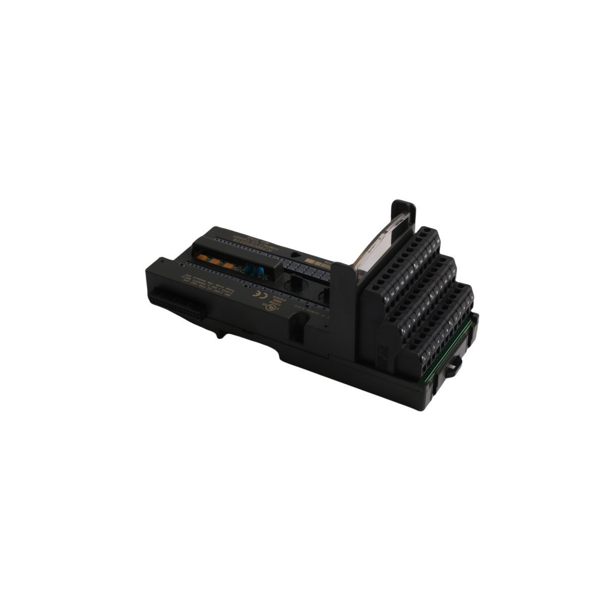
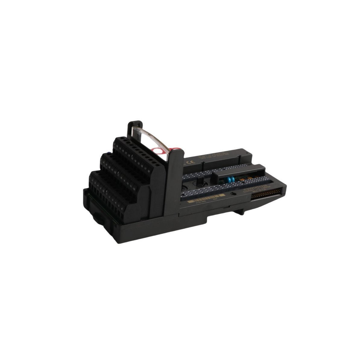
The Allen-Bradley 1794-TB3K, also cataloged as the 1794-TB3K Base Unit, operates as a dedicated hardware component for field device termination and modular I/O mounting within FLEX I/O control networks.
Hardware Specifications
Parameter
Specification
Model
1794-TB3K
Brand
Allen-Bradley
Origin
USA
Weight
0.9 kg
Dimensions
3.5 cm x 13 cm x 14.5 cm
Operating Temp
-20 deg C to 70 deg C
Power Consumption
Not specified
Current Rating
10 A at 125 V AC/DC
Industrial Control System Connectivity
The 1794-TB3K integrates into industrial control architectures by utilizing backplane bus communication velocity protocols for real-time data exchange. This terminal base architecture facilitates I/O density scaling within the control cabinet, which allows engineers to coordinate power distribution across multiple feedback loops. Furthermore, the module supports firmware flash compatibility via the associated I/O adapter, ensuring that system logic aligns with operational requirements. Consequently, the hardware ensures deterministic signal transmission during power threshold excursions.
Frequently Asked Questions (FAQ)
Q: Does the 1794-TB3K support hot-swapping of I/O modules?
A: Yes, the 1794-TB3K terminal base supports the removal and insertion of compatible FLEX I/O modules while the system is powered, provided that the associated module design permits such operations.
Q: What is the maximum wire gauge supported by the screw-clamp terminals?
A: The terminal blocks accommodate stranded copper wires ranging from 24 AWG to 16 AWG; for optimal mechanical and electrical contact, maintain a torque setting between 0.56 Nm and 0.79 Nm.
Field Installation Guidelines
To begin with, verify that the DIN rail is securely mounted and properly grounded before you position the terminal base; subsequently, hook the unit onto the rail and press firmly until the locking mechanism engages.
Furthermore, ensure all power to the I/O bus is isolated before you land any field wiring to the terminal blocks; meanwhile, strip the insulation according to manufacturer specifications to prevent exposed copper.
In addition, torque each screw-clamp to the specified 0.56-0.79 Nm range to ensure a vibration-resistant connection; then, verify that no conductor strands are pinched between the terminal and the housing.
Following wiring, perform a point-to-point continuity check to confirm that signal paths align with your schematic; by doing so, you mitigate the risk of short-circuits during system power-up.
Finally, snap the compatible I/O module onto the base until it clicks into place; thereby, you establish a secure electrical interface for the FLEX I/O network.
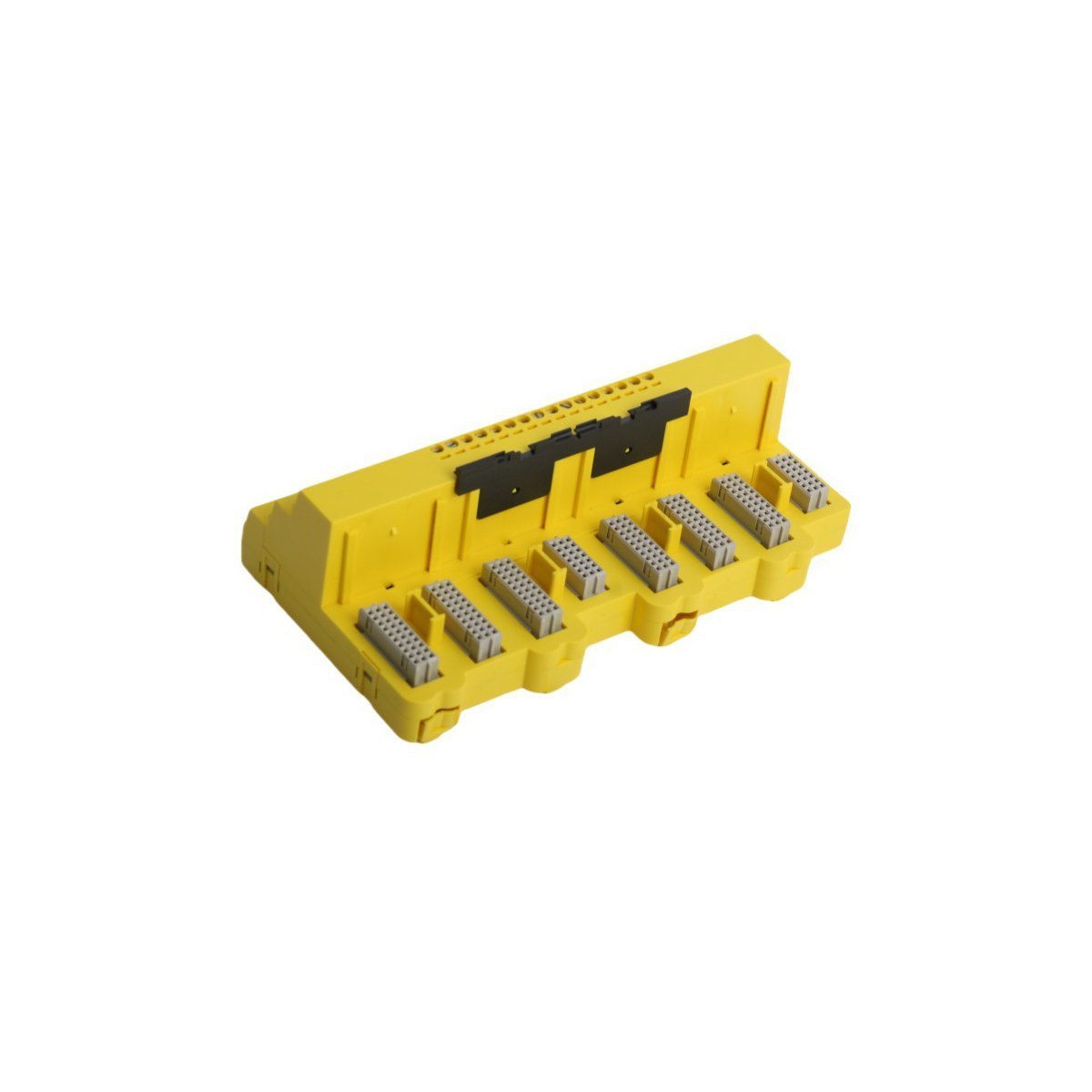
Configured for signal distribution in DeltaV M-series I/O Subsystem networks, the Emerson KJ4001X1-CA1 12P0623X072 (KJ4001X1-CA1 4-Wire Terminal Block) provides direct physical/electrical execution.
The KJ4001X1-CA1 functions as a passive interconnect interface within the DeltaV DCS architecture and facilitates direct field-to-I/O card connectivity. This terminal block secures 4-wire field signal connections and ensures consistent electrical continuity for both analog and discrete signal loops. Field engineers must follow DeltaV backplane wiring standards to maintain signal integrity and prevent impedance mismatches throughout the control loop. The design accommodates high-density terminal mounting and provides a structured physical path for 4-20 mA HART loop protocol signals, which standard process instrumentation requires.
Frequently Asked Questions
Q: Does the KJ4001X1-CA1 terminal block require external power for operation?A: No, this is a passive component. It functions solely as a physical connection interface for field wiring to the I/O subsystem backplane.Q: Is this module compatible with live field-wiring replacement?A: The terminal block supports field-wiring termination maintenance, but users must ensure the associated I/O card is powered down or in a safe state before disconnecting wiring to avoid accidental loops or short circuits.
Field Installation Guidelines
Mount the terminal block securely onto the designated DIN-rail within the DeltaV I/O carrier.
Ensure all terminal screws are tightened to the torque specifications provided in the DeltaV installation manual to prevent high-resistance contact points.
Verify wire gauges comply with terminal specifications to ensure mechanical stability.
Maintain proper wire dressing and cable tie-down spacing to prevent mechanical stress on the terminal connectors.
Ground the cable shields according to standard DCS loop-wiring practices to minimize electromagnetic interference (EMI) ingress into the analog signal path.
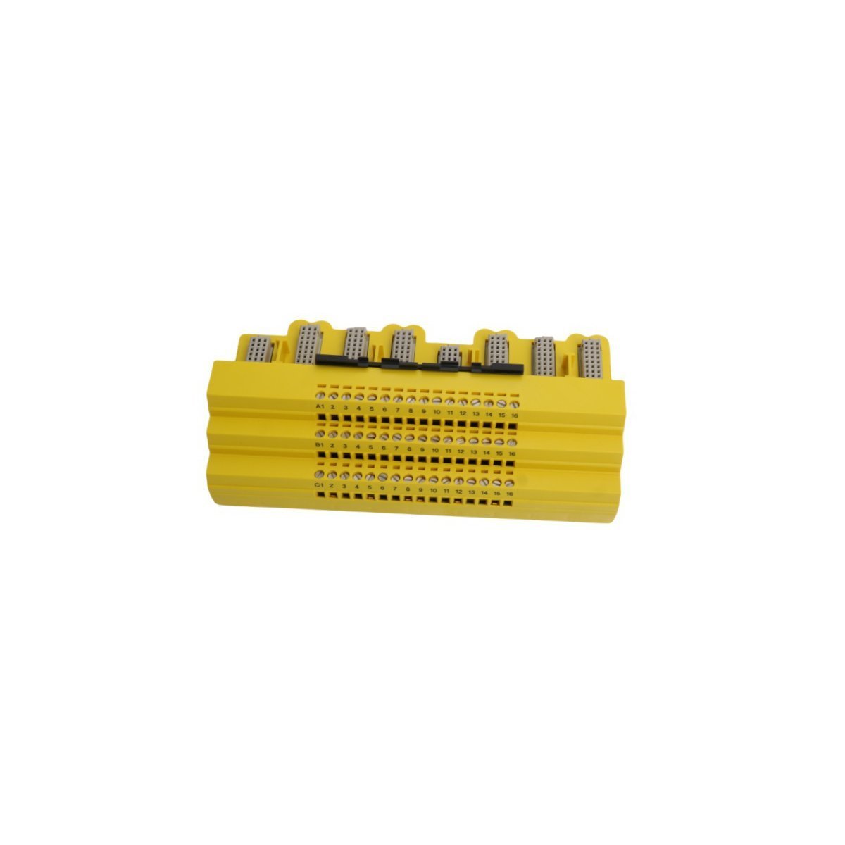
Configured for signal termination in DeltaV SIS process safety system networks, the Emerson KJ2201X1-JA1 12P3323X022 (KJ2201X1-JA1 SLS Redundant Terminal Block) provides direct physical/electrical execution.
The KJ2201X1-JA1 functions as a passive interconnect interface within the DeltaV SIS architecture and facilitates direct field-to-I/O card connectivity. This terminal block secures redundant field signal connections and ensures consistent electrical continuity for critical safety loops. Field engineers must follow DeltaV backplane wiring standards to maintain signal integrity and prevent impedance mismatches throughout the safety control loop. The design accommodates high-density terminal mounting and provides a structured physical path for signals requiring 4-20 mA HART loop protocol connectivity, which standard process instrumentation demands.
Frequently Asked Questions
Q: Does the KJ2201X1-JA1 require external power for internal switching?A: No, this unit is a passive termination component. It relies on the connected DeltaV SIS I/O card for logic execution and loop power distribution.Q: How does this terminal block support redundant system configurations?A: The hardware architecture provides dual-path termination points, allowing the SIS controller to monitor and execute fail-safe state transitions across redundant signal channels without hardware reconfiguration.
Field Installation Guidelines
Secure the terminal block onto the specified DIN-rail mounting position within the DeltaV SIS carrier.
Tighten all terminal screws to the manufacturer-specified torque limits to prevent intermittent contact resistance under vibration.
Terminate field wiring according to the loop diagram to ensure correct channel mapping.
Route shielded cables through designated cable trays to minimize electromagnetic interference (EMI) impact on analog signal precision.
Verify electrical continuity across the redundant paths using a calibrated multimeter before energizing the I/O loop.
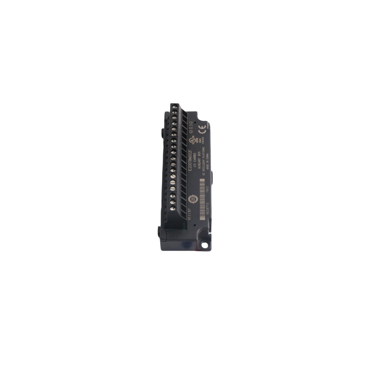
The GE IC200TBM002, also cataloged as the IC200TBM002 I/O terminal block, operates as a dedicated hardware component for signal distribution and wiring termination within VersaMax PLC systems. Configured for high-density I/O routing, the block provides direct physical execution of signal bussing through 18 integrated IEC-compliant box-style terminals. This module facilitates electrical interfacing for input/output carriers and interposing terminals, ensuring standardized connectivity for industrial field wiring.
Hardware Specifications
Parameter
Specification
Model
IC200TBM002
Brand
GE
Origin
USA
Weight
0.06 kg
Dimensions
11.0 cm x 3.5 cm x 3.0 cm
Operating Temp
Standard Industrial Range
Power Consumption
Passive (No active components)
Voltage Rating
264 VAC (Up to 300 VAC tolerance)
Current Rating
8 A
PLC and Control Network Integration
The VersaMax series utilizes modular backplane bus communication velocity and deterministic synchronization to manage distributed I/O blocks. Moreover, firmware flash compatibility within the host CPU allows for systematic updates across the network, thereby ensuring that hardware configurations remain consistent with logic execution cycles. In addition, I/O density scaling is supported through the flexible mounting interface, which enables the system to expand without exceeding the timing constraints of the host bus. Finally, Profinet and EtherNet/IP deterministic network integration requirements are managed upstream via communication modules, while the IC200TBM002 serves as the physical termination point for local field signals.
Frequently Asked Questions
Q: Does the IC200TBM002 provide electrical isolation between terminals?A: The IC200TBM002 features 18 internally-bussed terminals. It is electrically isolated from the I/O carrier interface; however, within the block itself, the terminals are bussed together to provide a common electrical potential.Q: What is the maximum wire gauge supported by the terminal block?A: The terminal block accommodates solid or stranded wires ranging from AWG #22 to AWG #14. It also supports the connection of two wires per terminal, provided the combined gauge does not exceed AWG #18.
Field Installation Guidelines
The module should be installed using the integrated mounting tabs on the top edge or secured via panel-mounting holes to ensure mechanical stability in high-vibration environments.
Ensure all field wiring is stripped to the appropriate length according to IEC standards before insertion into the box-style terminals to prevent short circuits.
When utilizing the terminal block for power distribution, ensure that the cumulative current across the 18-point bus does not exceed the 8 Amp rating.
Verify proper seating within the insert-slots of the I/O carrier to ensure the mechanical and electrical integrity of the VersaMax I/O assembly.
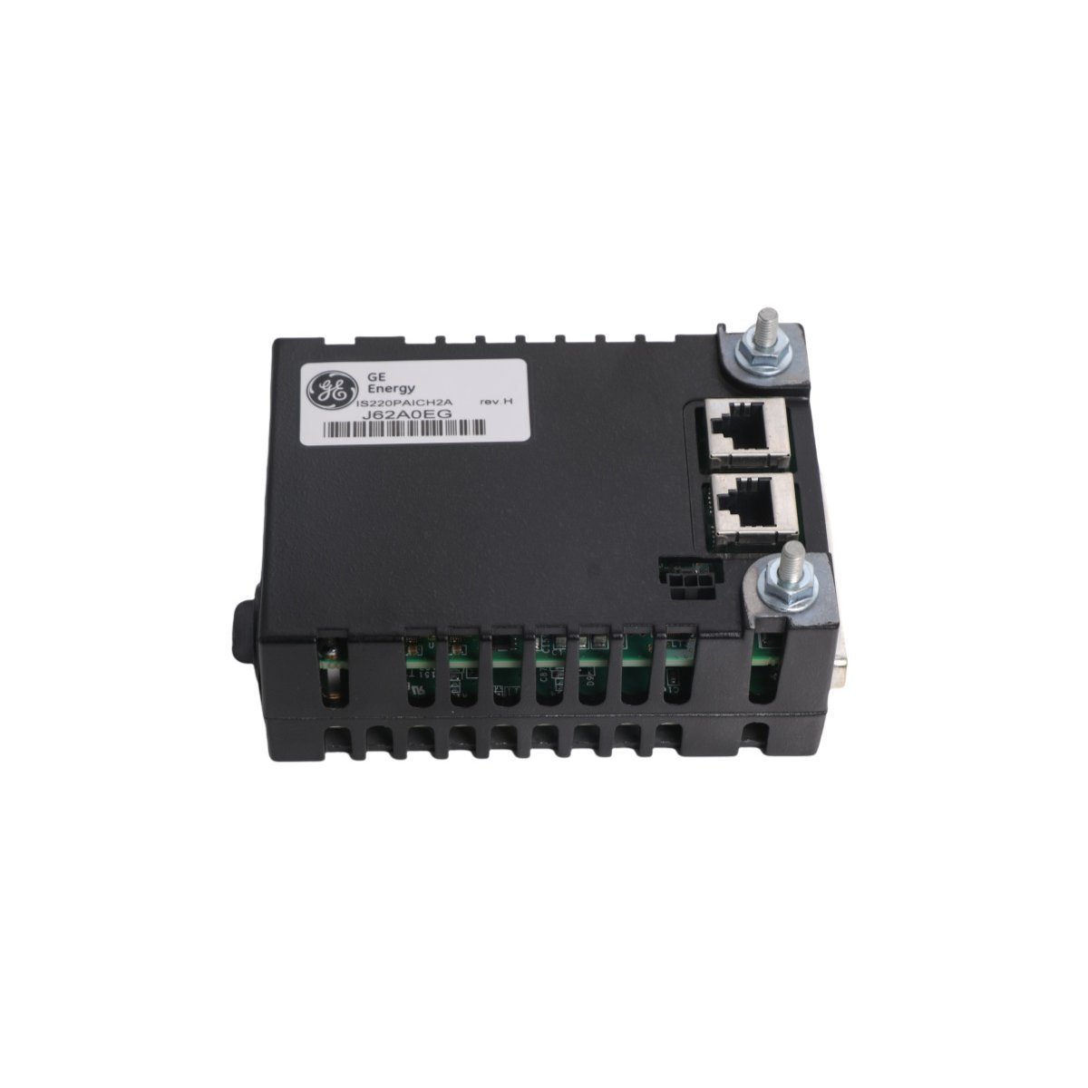
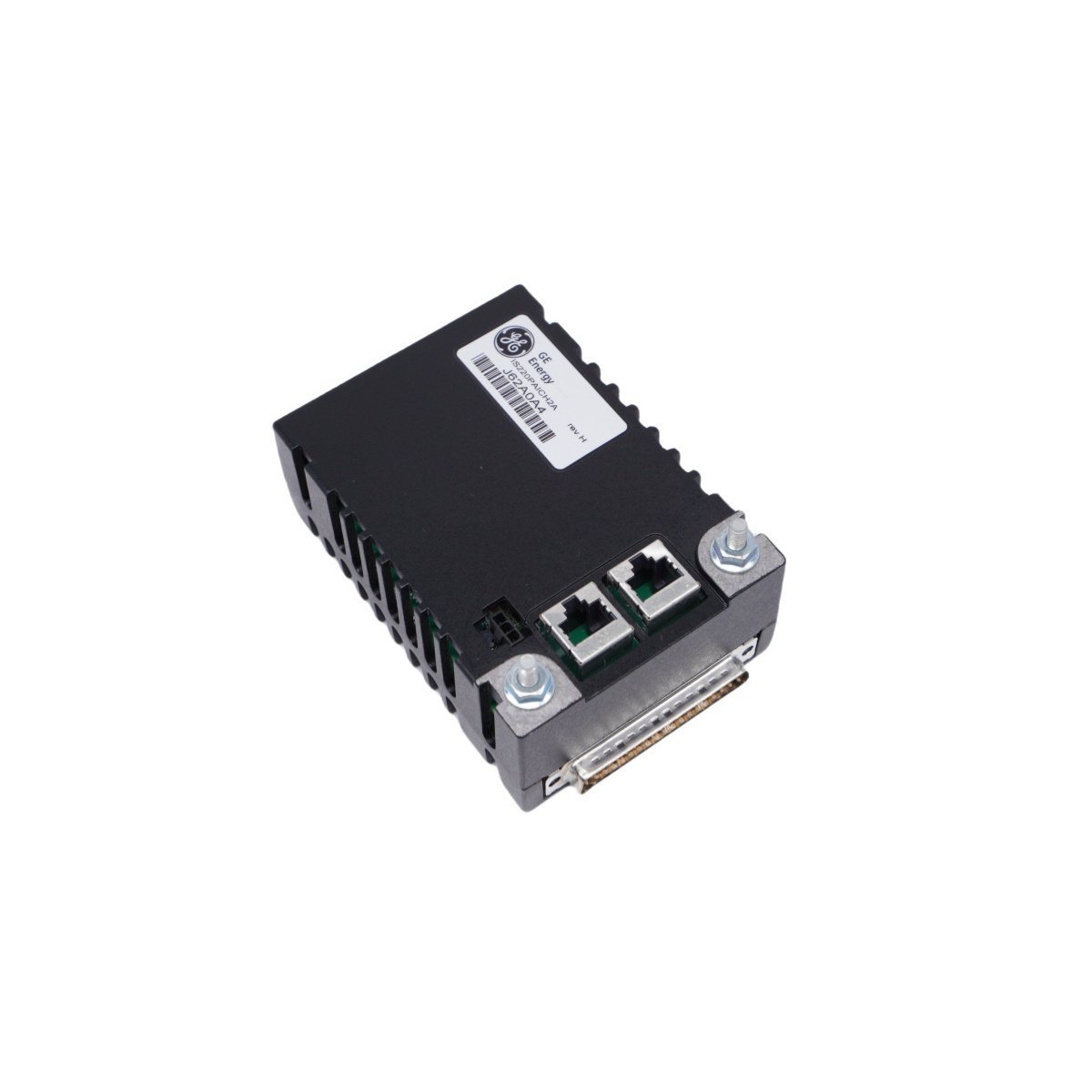
The GE IS220PAICH2A is a high-performance analog I/O pack for Mark VIe turbine control systems. It features 10 configurable analog inputs and 2 current loop outputs, supporting both simplex and TMR configurations for critical process control and monitoring.
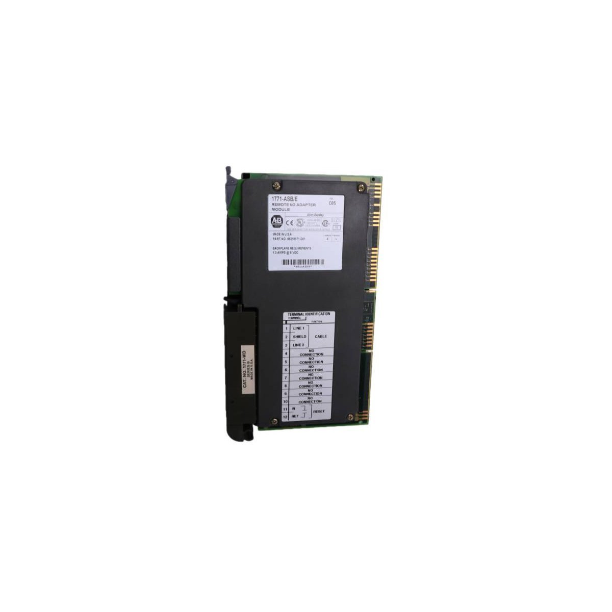
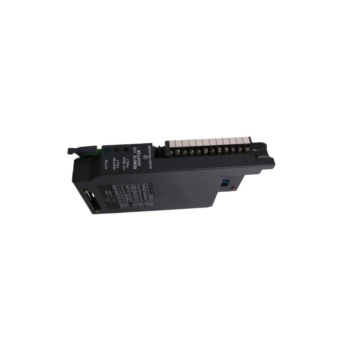
The Allen-Bradley 1771-ASB/E is a universal Remote I/O adapter module for PLC-5 systems, designed to enable efficient distributed I/O communication and diagnostics.
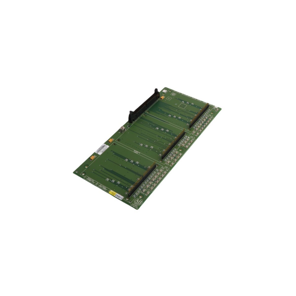
The Allen-Bradley 80190-600-01-R is an industrial optical interface base circuit board. Brand New, Original Stock, Global Shipping available for immediate deployment.
The GE Fanuc IC200CHS022 is a 36-terminal, box-style I/O carrier for the VersaMax series. It supports high-density field wiring, DIN-rail mounting, and tool-free module replacement to maximize system uptime and reliability.
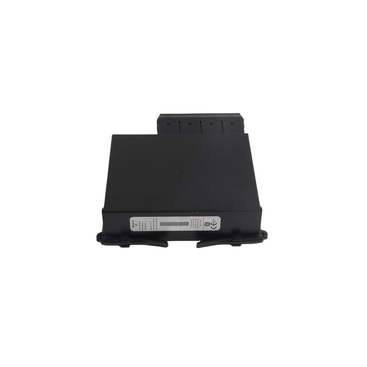
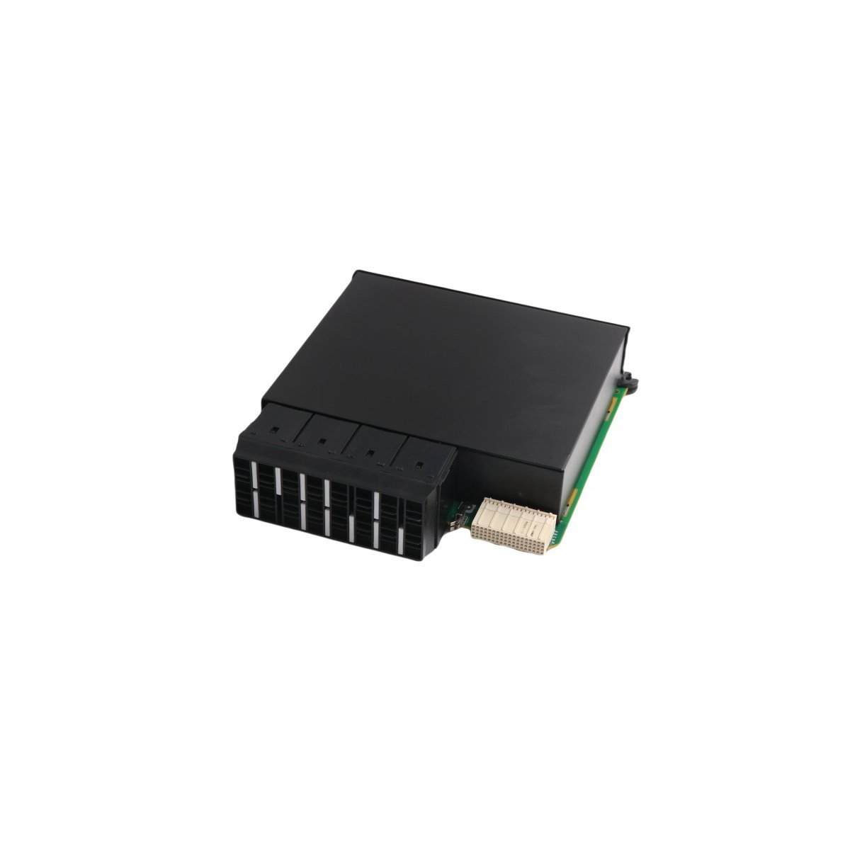
The GE Multilin UR6DV is a versatile Digital I/O module designed for the Universal Relay series. It features a compact 0.36kg design with integrated digital inputs and outputs for substation automation. This genuine GE component provides reliable status monitoring and control switching for DCS and protective relaying applications.
The Emerson KJ4001X1-BE1 (12P0818X072) provides a robust 8-wide I/O carrier solution for the DeltaV M-series subsystem. It features high-density module mounting, integrated power distribution, and reliable signal routing for advanced DCS industrial automation environments.
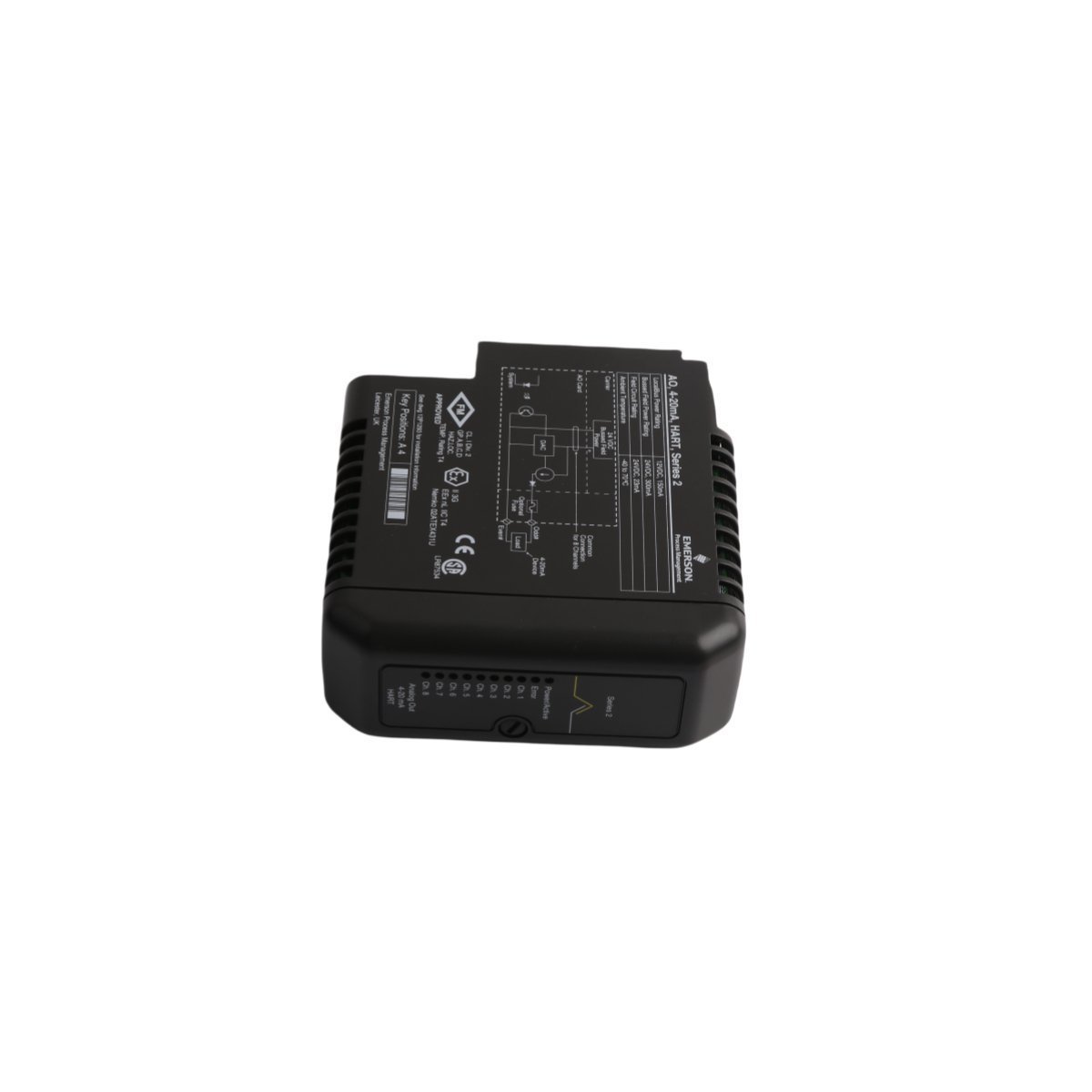
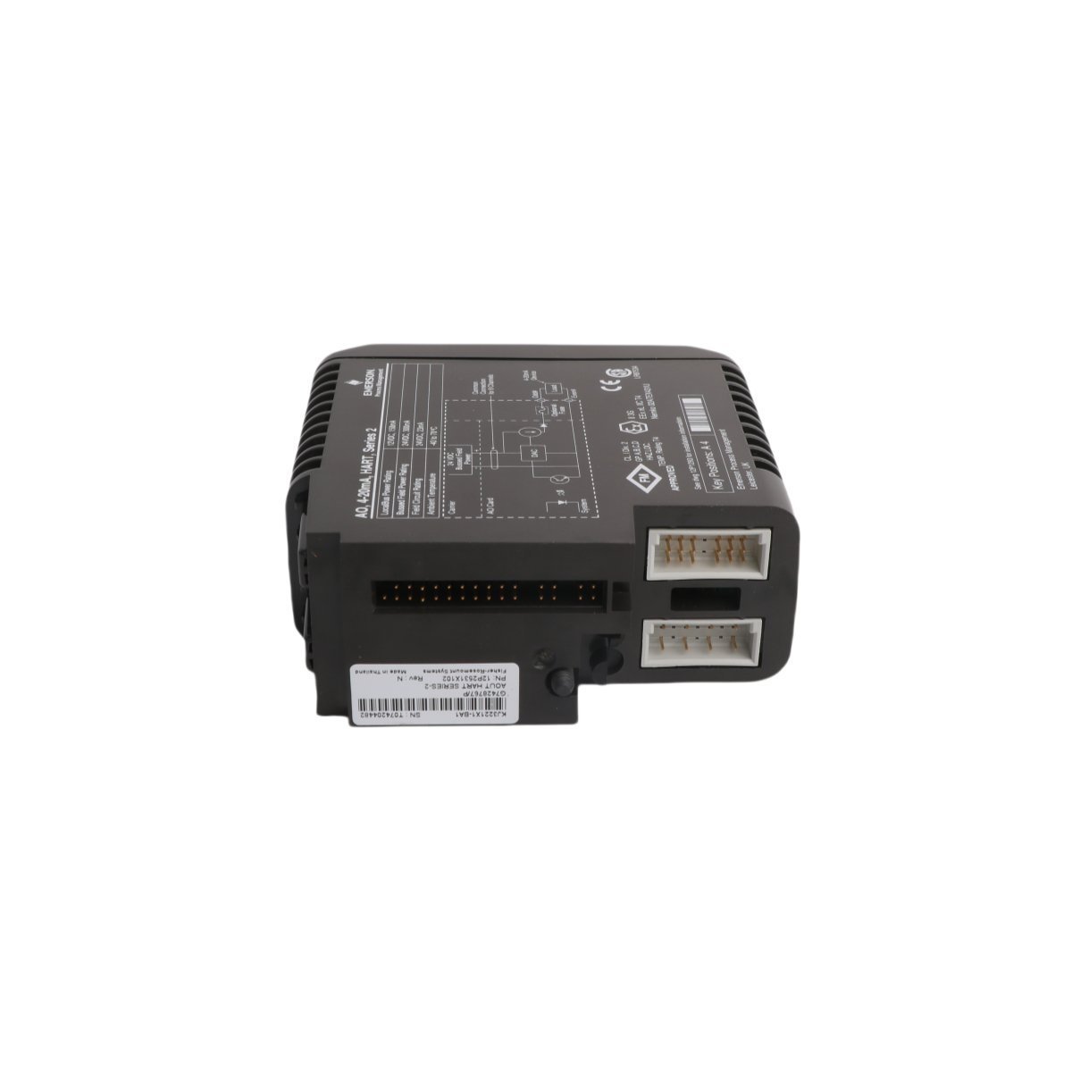
The Emerson KJ3221X1-BA1 (12P2531X062) is a high-reliability DeltaV Redundant I/O Baseplate designed for Series 2 systems. It enables seamless module redundancy and hot-swappable maintenance for critical DCS applications in harsh industrial environments.
The GE Multilin UR6TH is a high-density 16-input and 8-output module for the Universal Relay (UR) platform. Designed for substation-grade protection and control, it offers reliable discrete signal interfacing for GE Multilin G60, L90, and other UR-series units.
The Emerson KJ3221X1-BA1 (VE4003S2B2) is a 32-channel, 24VDC discrete output module for DeltaV S-series systems. Featuring advanced loop diagnostics, high-density switching, and hot-swap capability, this module provides reliable and fault-tolerant control for solenoid valves and relays in demanding process environments.
We are committed to protecting your privacy. The information collected here is strictly used to provide the requested quotes, technical support, and relevant industrial automation solutions.