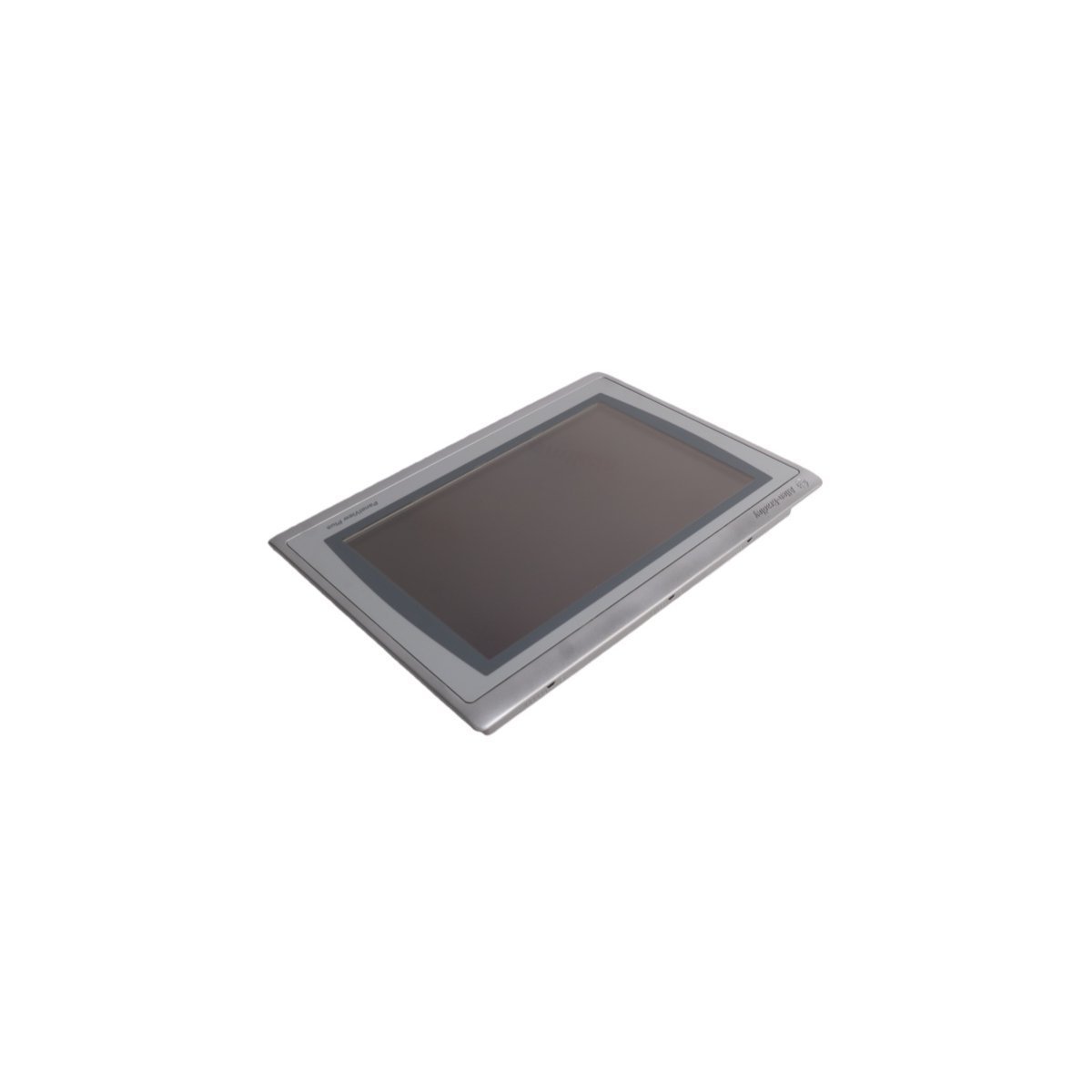
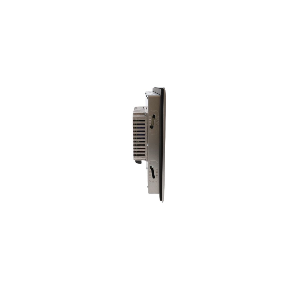
You are here:
SKU: FS-FANWR-24R

HONEYWELL FS-FANWR-24R Fan Assembly Kit

Order original HONEYWELL FS-FANWR-24R DCS cabinet fan assembly kits. Features dual axial fans, integrated PCB 07209 control tracking, and dry contact monitoring output. In stock and certified for industrial environments.

The HONEYWELL FS-FANWR-24R is a high-reliability active thermal management module engineered specifically for industrial control enclosures, distributed control systems (DCS), and programmable logic controller (PLC) rack assemblies. Operating on a nominal 24VDC power supply, this dual-fan assembly prevents localized heat buildup within high-density component arrays. It features integrated operational monitoring electronics and an independent hardware-driven readback circuit to ensure forced-air cooling integrity in mission-critical environments.

Technical Specifications

ParameterSpecification
Model NumberFS-FANWR-24R
ManufacturerHONEYWELL
OriginUSA
Mechanical ProfileDual axial fans mounted on a rigid structural baseplate
Dimensions12 x 19 x 2 cm
Weight0.15 kg
Operating Voltage Range12 to 29 VDC (24VDC Nominal)
Power Consumption9.5 W
Overcurrent ProtectionIntegrated 2A slow-blow fuse
Monitoring OutputPotential-free (dry) readback contact
Relay Contact RatingMax 300 VDC / 240 VAC @ 0.5 A
Interface Connection4-pole removable plug-in connector block
Safety FeaturesDual-sided integrated metal finger guards
HS Code8537101190

Internal Electronics & Monitoring Logic

The FS-FANWR-24R is equipped with a dedicated internal control board (PCB 07209) that continually tracks the performance parameters of both brushless DC motors. Rather than relying purely on voltage presence, the board evaluates true rotor speed (RPM) via sensor feedback loops:

  • Visual Telemetry: Each fan motor corresponds to a dedicated green LED on the face of the assembly frame. The LED remains steadily illuminated only when the respective rotor velocity is verified above the minimum operating speed threshold.
  • Fault-Tolerant Readback Circuit: The module provides a hardwired, potential-free (dry) readback contact wired to the external 4-pole interface. This contact remains closed during normal operation when both fans are spinning above their required velocity.
  • Alarm Interlocking: If either fan fails, drops in RPM, or suffers an electrical stall, the internal control relay de-energizes, dropping the readback contact open. This state change can be directly monitored by an auxiliary digital input channel on a supervisory PLC/DCS node to flag a thermal fault before temperatures reach critical safety levels.

Frequently Asked Questions

Q: Can this fan unit run directly off an unregulated 12VDC backup battery source?

A: Yes. The board is designed with an extended input tolerance range stretching from 12 to 29 VDC. However, note that running the unit continuously at lower voltages reduces the maximum CFM (cubic feet per minute) airflow output, which can lower total heat dissipation performance inside the cabinet.

Q: Is the 2A slow-blow fuse on the PCB user-replaceable in the field?

A: The 2A slow-blow fuse is a board-mounted protective component intended to halt catastrophic circuit failure if a fan motor shorts out. While it can be replaced by an instrumentation technician using proper desoldering tools, standard field maintenance procedures recommend swapping out the complete assembly kit to preserve the system’s strict environmental certifications.

Q: What happens to the readback signal if a single fan fails but the other operates normally?

A: The readback relay logic functions in a strict series loop configuration. If even a single fan falls below the safe RPM threshold, the potential-free contact opens immediately. This ensures the supervisory system treats a partial cooling failure with the same priority as a total cooling breakdown.


Field Installation Guidelines

  • Interface Plugging: Route the 24VDC power supply lines and the external monitoring circuit through the keyed 4-pole terminal plug before mating it to the assembly socket. Ensure the connection clicks into place to prevent resistance issues from vibration.
  • Airflow Vectors: Verify the air direction arrow stamped on the module’s frame matches your cabinet’s thermal strategy. Mount the unit to pull hot exhaust air out of the card rack or drive fresh air over heat sinks.
  • Clearance Protection: Keep area zones directly outside the dual-sided finger guards clear of wiring bundles or loose documentation that could obstruct the intake paths or foul the fan blades.
  • Cabinet Integration: Secure the mounting plate tightly to the rack enclosure using the built-in screw positions. A firm mechanical connection dampens frame resonances and minimizes acoustic noise in the control environment.