Sale!
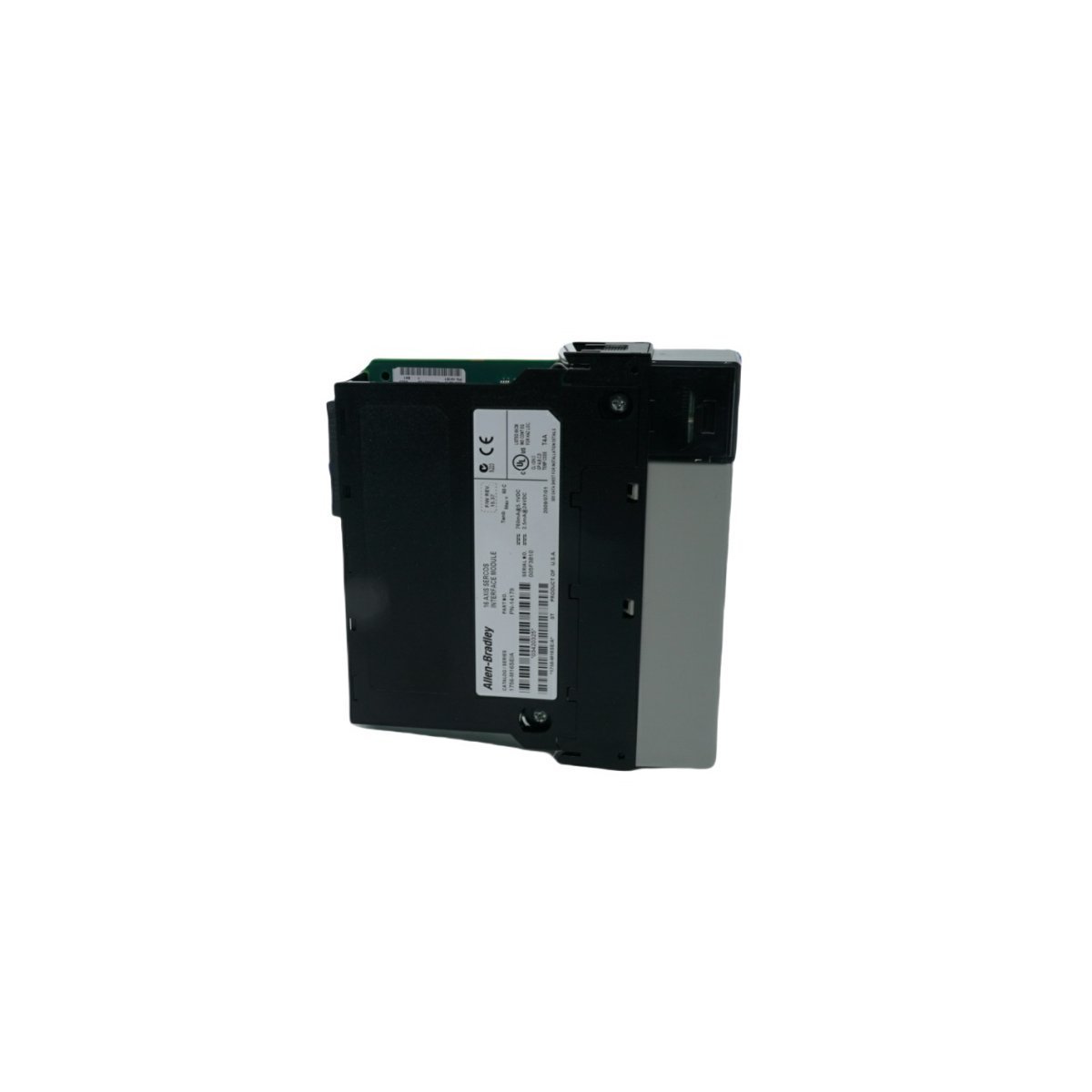
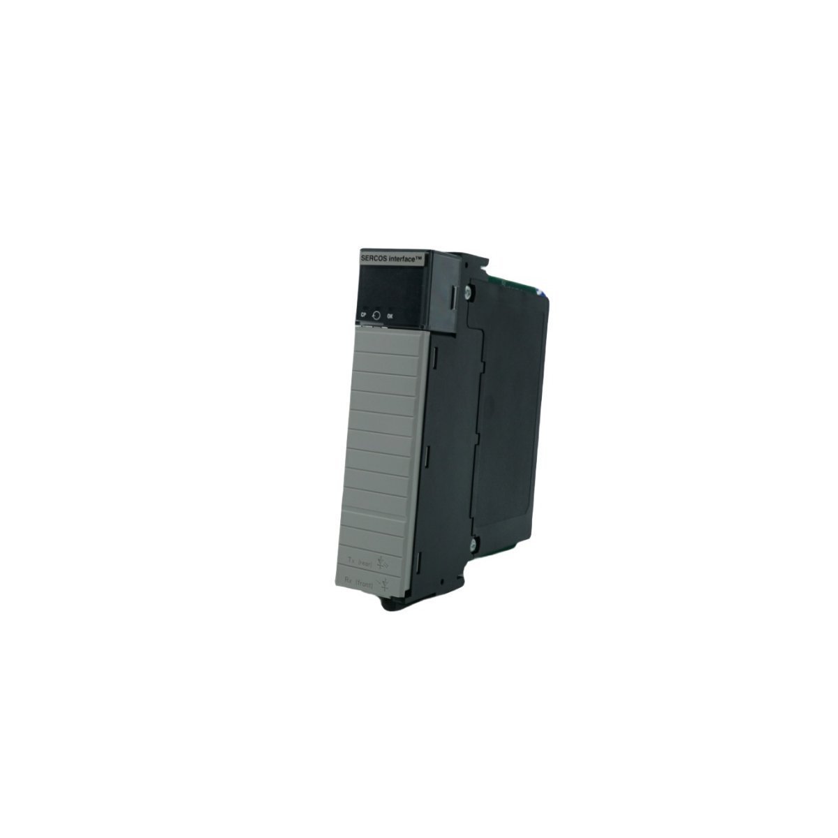
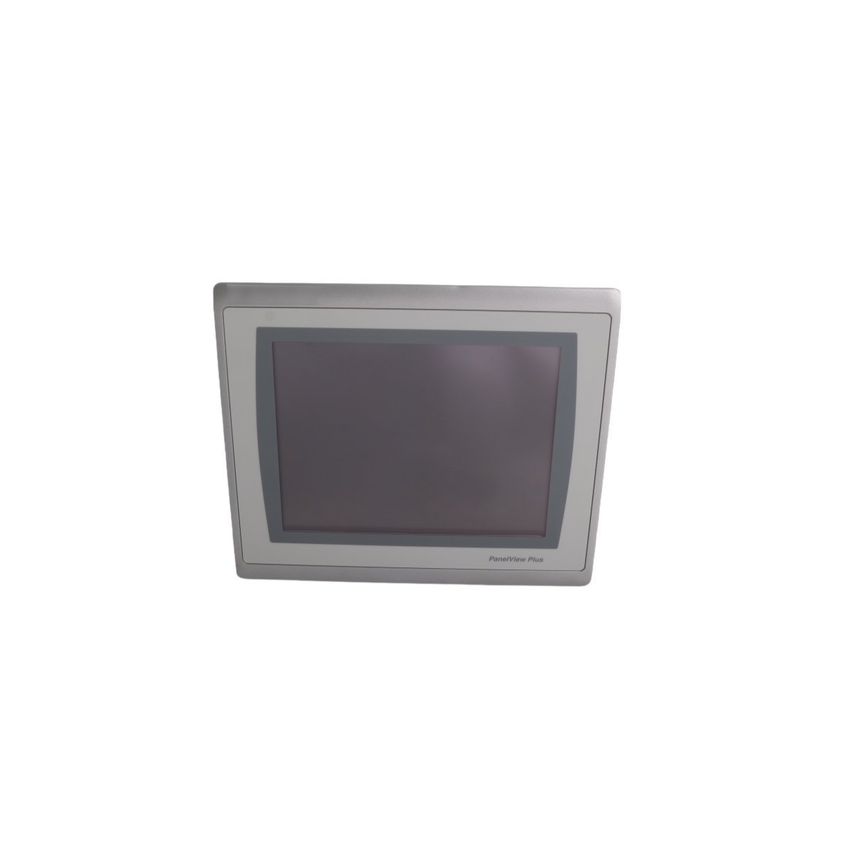
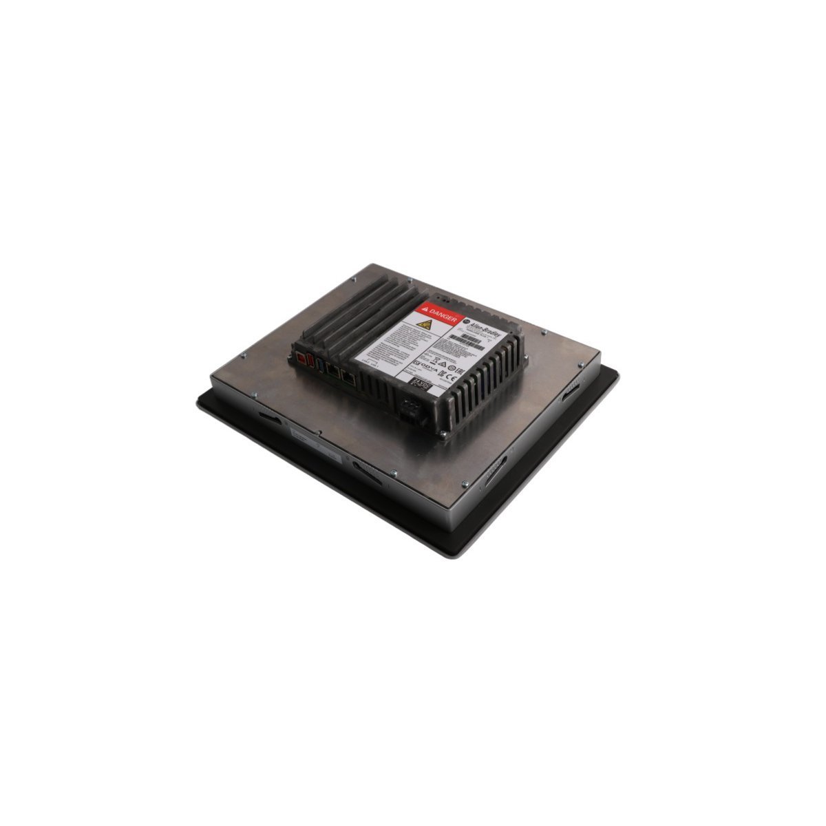
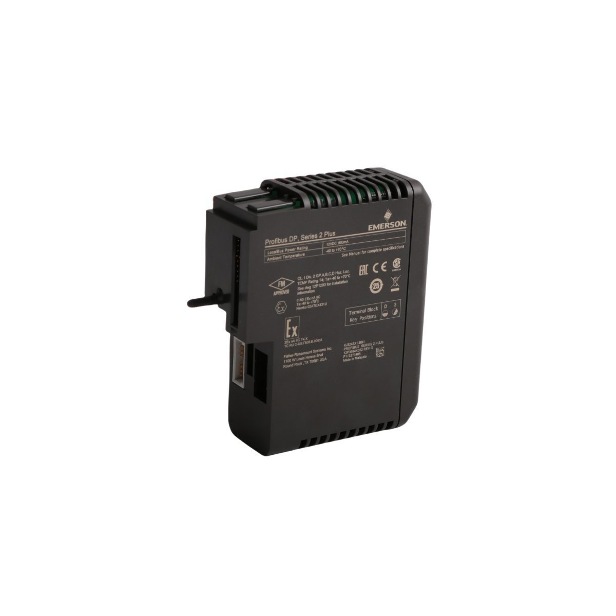
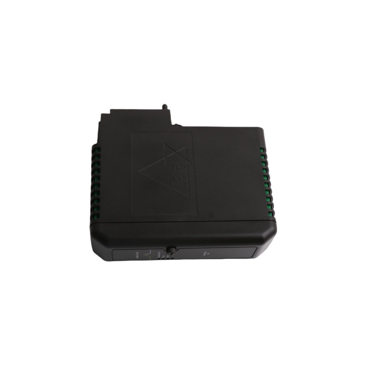
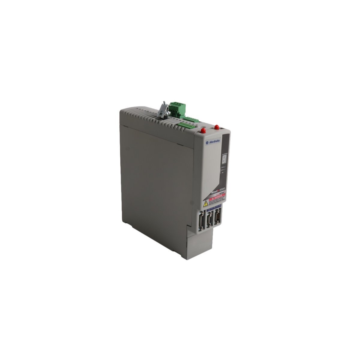
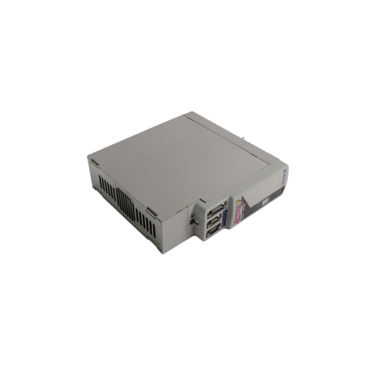
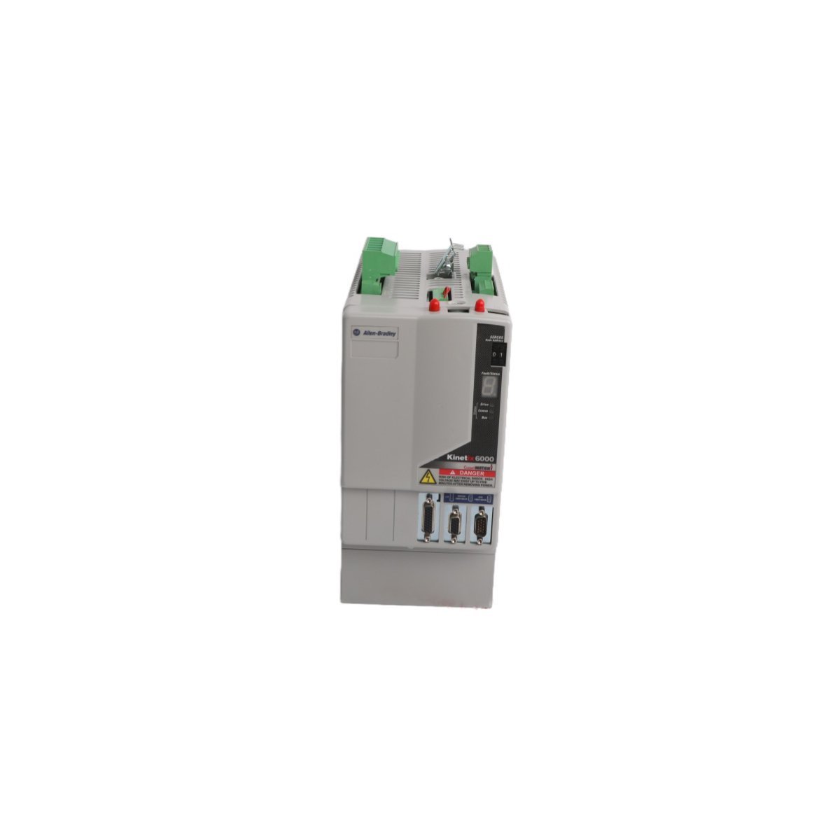
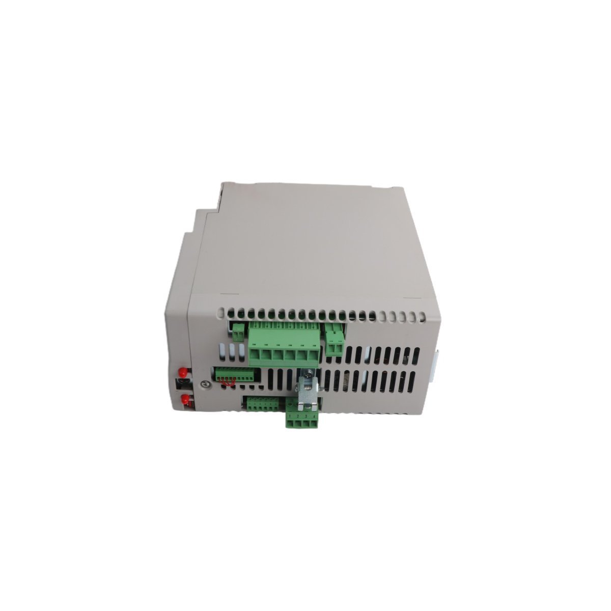
Allen-Bradley 1756-M16SE SERCOS interface Module
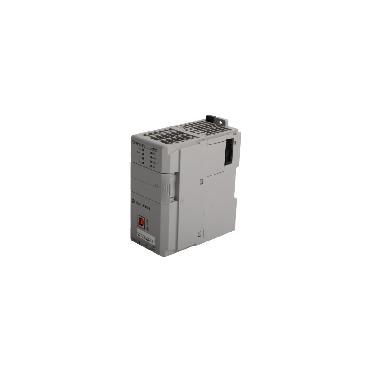
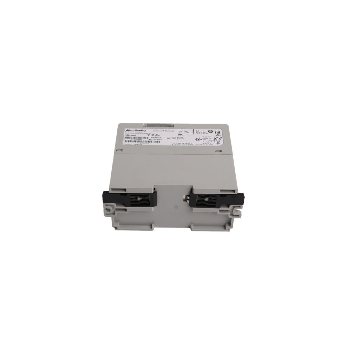
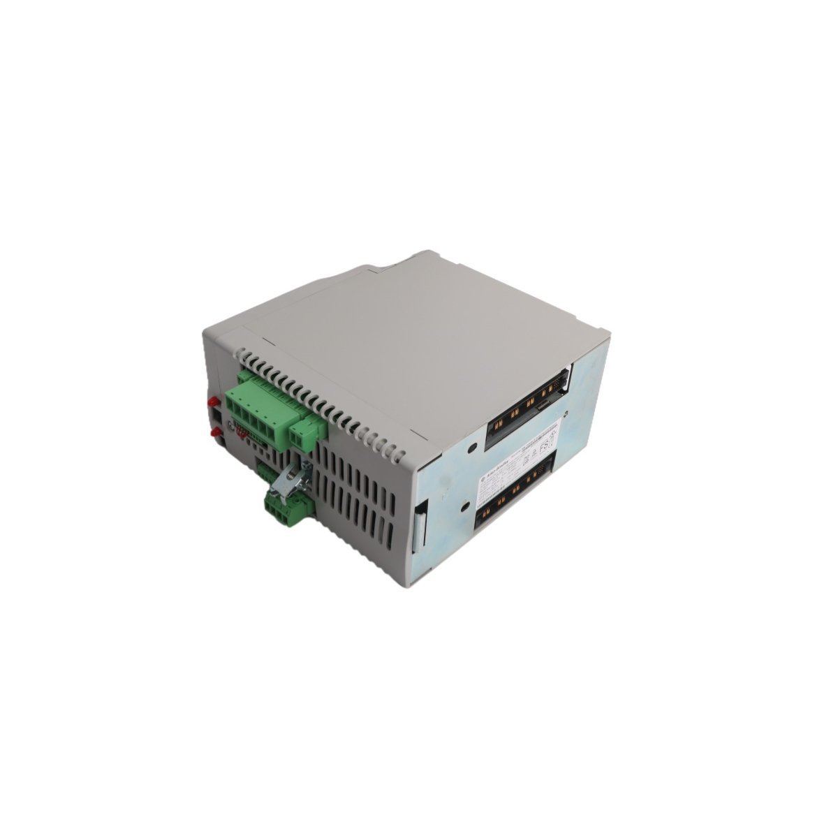
Configured for high-speed motion synchronization in ControlLogix systems, the Allen-Bradley 1756-M16SE (1756-M16SE SERCOS interface Module) provides direct physical and electrical execution for multi-axis servo drive command distribution.
Hardware Specifications
| Parameter | Specification |
| Model | 1756-M16SE |
| Brand | Allen-Bradley |
| Origin | USA |
| Weight | 0.22 kg |
| Dimensions | 3.5 cm x 14 cm x 14.5 cm |
| Operating Temp | Standard industrial range |
| Power Consumption | Backplane dependent |
| Data Rate | 4 Mbps or 8 Mbps |
| Axis Capacity | 16 axes per module |
PLC Control and Communication Characteristics
The 1756-M16SE utilizes high-speed backplane bus communication velocity to manage deterministic data exchange between the ControlLogix CPU and remote servo drive nodes. By leveraging digital fiber-optic SERCOS interfaces, the module achieves I/O density scaling that minimizes signal propagation latency across 16 managed axes. Furthermore, the module supports firmware flash compatibility, which allows for site-specific motion algorithm updates without physical hardware replacement. This deterministic network structure ensures that position, velocity, and torque command loops maintain sub-millisecond synchronization even in high-density drive configurations.Frequently Asked Questions (FAQ)
Q: What are the primary limitations when configuring the SERCOS ring topology for the 1756-M16SE?A: The ring topology is limited by the physical length of the fiber-optic cabling and the total number of connected nodes; you must ensure the total loop latency does not exceed the configured cycle time (0.5 ms or 1.0 ms) to maintain deterministic operation.Q: Is the 1756-M16SE module capable of hot-swapping within an active ControlLogix chassis?A: The module supports standard ControlLogix hot-swap procedures; however, removing the module will immediately drop the SERCOS ring communication, causing all connected servo drives to transition to their programmed fault state.Field Installation Guidelines
- To begin with, confirm the ControlLogix chassis backplane is powered down; subsequently, insert the 1756-M16SE into a designated slot and secure it using the integrated module locking screws to ensure proper backplane contact.
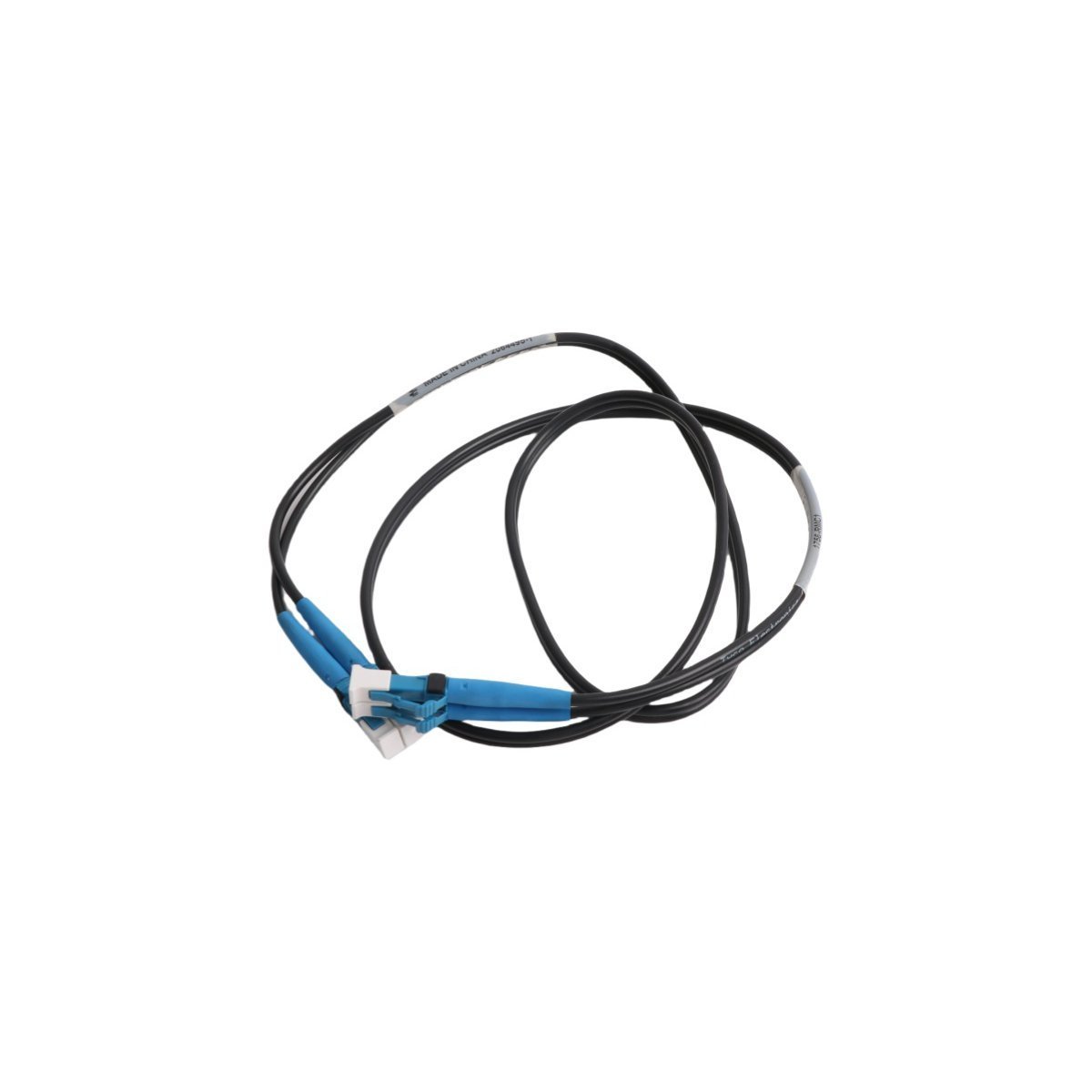
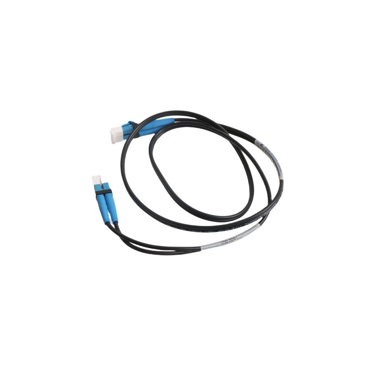
- In addition, route the SERCOS fiber-optic cables following the ring or linear topology requirements; meanwhile, maintain the minimum bend radius of the fiber to prevent micro-fractures that induce signal loss.
- Furthermore, ensure all fiber-optic connectors are clean and free of contaminants before insertion into the module transceivers; consequently, this prevents optical attenuation that could lead to intermittent link failures.
- Finally, configure the module addressing and axis scaling within the control software; by doing so, you ensure the controller can successfully establish the SERCOS communication cycle with the downstream Kinetix drives.