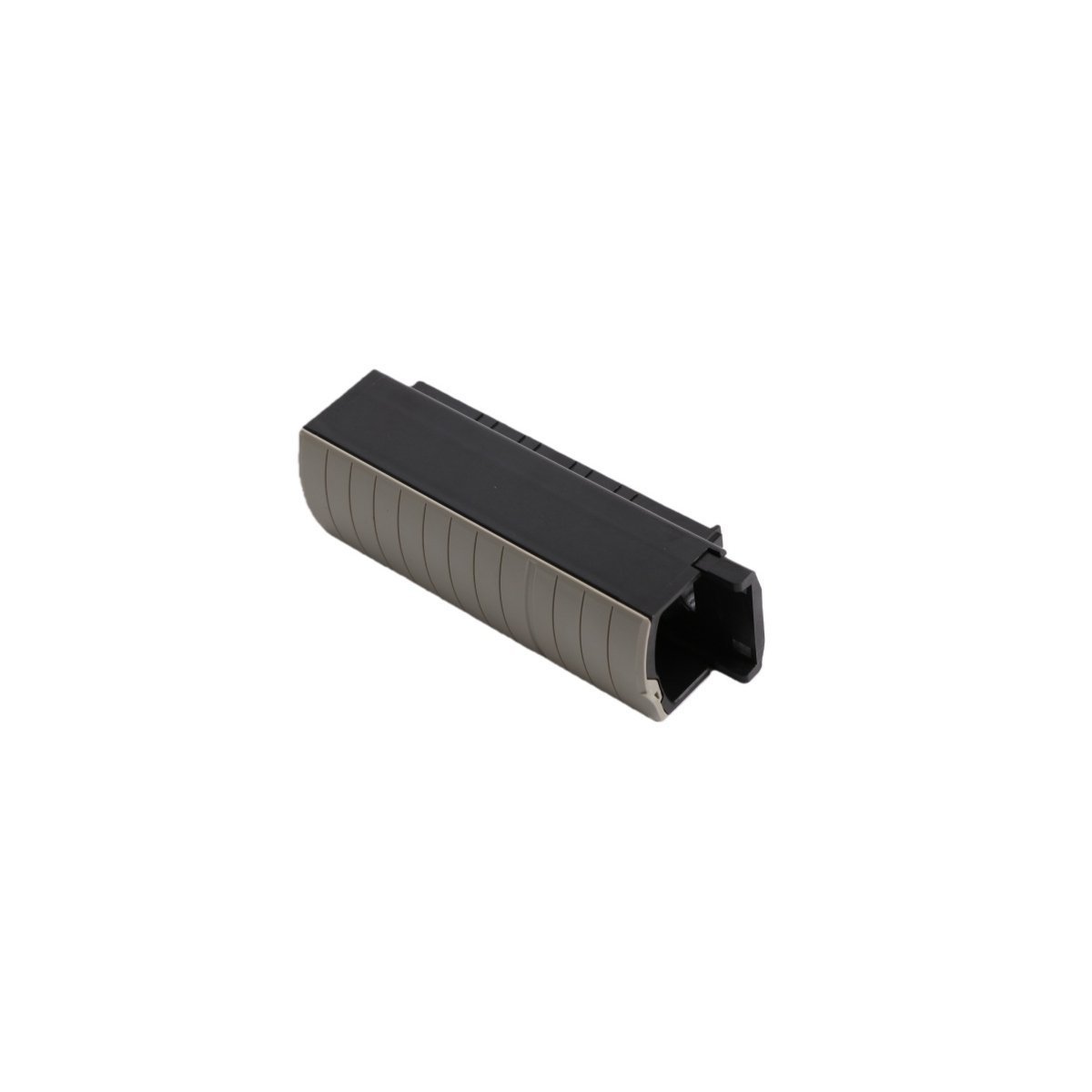
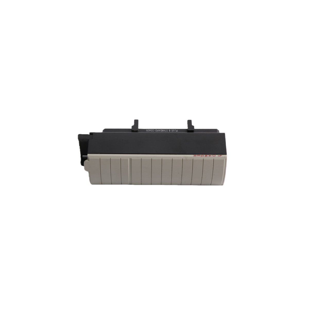
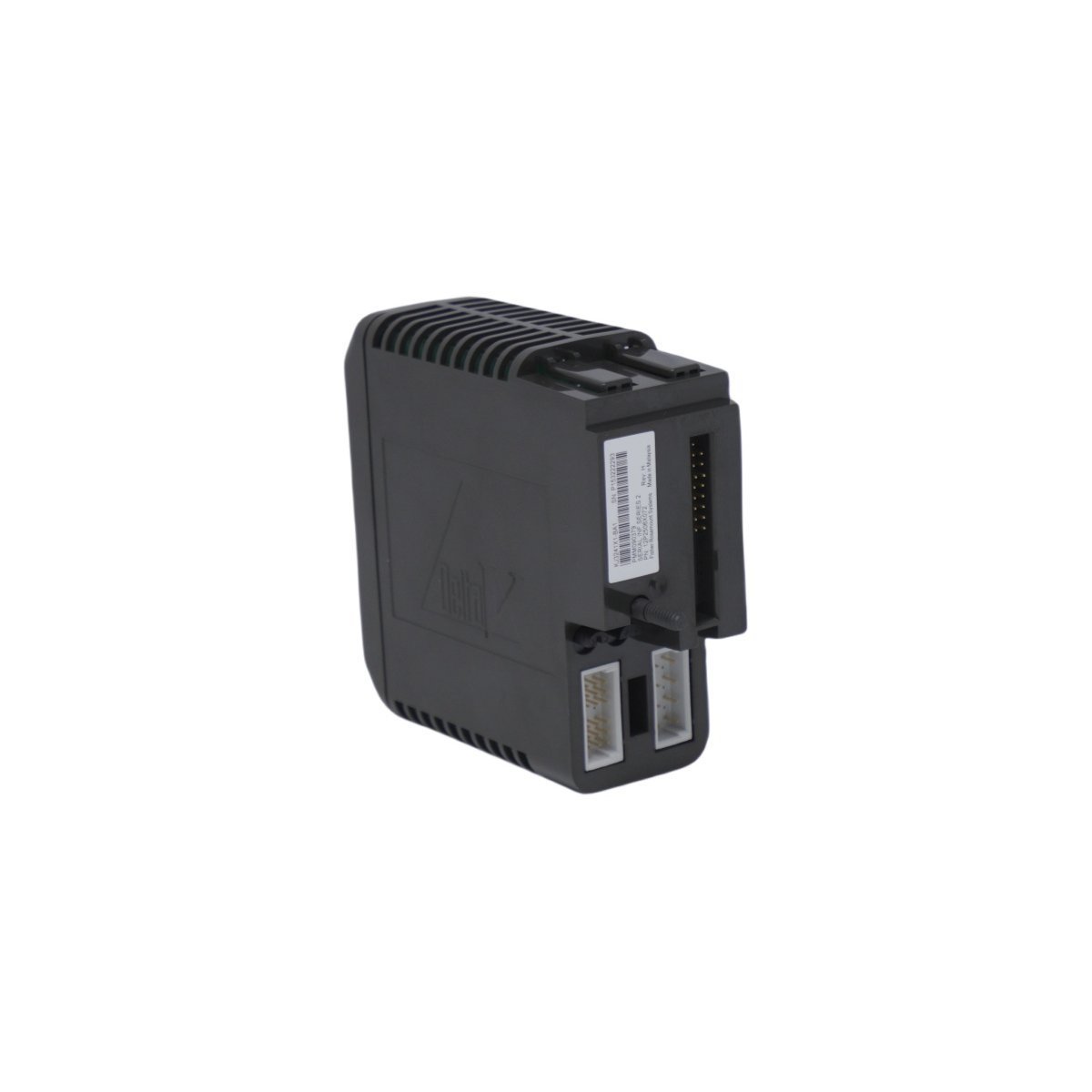
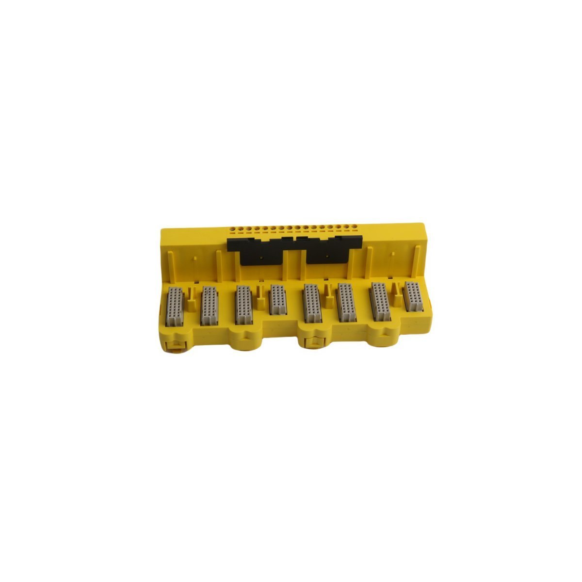
You are here:
SKU: Allen Bradley 1756-RMC1

Allen Bradley 1756-RMC1 ControlLogix System Component

Allen Bradley 1756-RMC1 ControlLogix redundancy link cable. Brand New, Original Stock with Global Shipping for high-availability automated industrial platforms.

The Allen Bradley 1756-RMC1, also cataloged as the 1756-RMC1 ControlLogix 1 m RM Fiber Optic Cable, operates as a dedicated hardware component for high-speed redundancy synchronization within ControlLogix chassis networks. It establishes the physical optical link between 1756-RM or 1756-RM2 redundancy modules to synchronize system state data across partner controller racks.

Hardware Specifications

ParameterSpecification
Model1756-RMC1
BrandAllen Bradley
OriginUSA
Weight0.02 kg
Dimensions102.0 x 1.2 x 1.0 cm
Operating TempStandard ControlLogix chassis limits
Power ConsumptionPassive optical component (0 W)
Cable Length1.0 m (3.28 ft)
Media TypeFiber optic
Core SubsystemControlLogix Redundancy System
HS Code8537101190

Industrial Networks & Drive Systems

The component provides the precise physical channel necessary for backplane bus communication velocity synchronization across redundant architectures. By maintaining deterministic optical transmission baselines, it enables dual-chassis lock-step firmware execution and minimizes switchover latency between primary and secondary ControlLogix controllers. This media standard maintains structural noise immunity against electromagnetic interference (EMI) across complex plant floor topologies.

Frequently Asked Questions

Q: Can the 1756-RMC1 cable be extended or coupled with standard commercial fiber adapters?

A: No. Redundancy synchronization links demand fixed attenuation profiles and specific propagation velocity metrics. Splicing or extending the optical media modifies transmission metrics, leading to synchronization timeouts or total link failure.

Q: Is this cable hot-swappable while the redundancy modules are active?

A: Disconnecting the redundancy cable while the system is under load causes an immediate loss of partner tracking. While hardware damage will not occur, the secondary chassis will transition to a non-synchronized state, disabling failover capabilities.

Field Installation Guidelines

  1. Inspect the fiber optic connectors on both ends of the 1756-RMC1 cable for particulate contamination prior to insertion. Clean using approved optical instrumentation if required.
  2. Route the cable between the two 1756-RM/RM2 redundancy modules, ensuring the physical layout does not exceed the minimum bend radius specifications.
  3. Align the retaining keys on the cable connector with the matching receptor port on the module interface.
  4. Insert the plug firmly until the integrated locking mechanism engages securely into the module socket.
  5. Secure the optical cable bundle away from high-voltage AC paths and sharp physical chassis components using non-crimping industrial zip ties.