Emerson DeltaV KJ4010X1-BG1 Localbus Right Extender
Sale!
SKU: KJ4010X1-BA1 12P1867X012 Localbus Right Extender
Emerson DeltaV KJ4010X1-BG1 Localbus Right Extender
Emerson DeltaV M-series Localbus Right Extender card (KJ4010X1-BG1 / 12P0830X072) for distributed control systems. Brand new original stock, fully verified with priority shipping options.
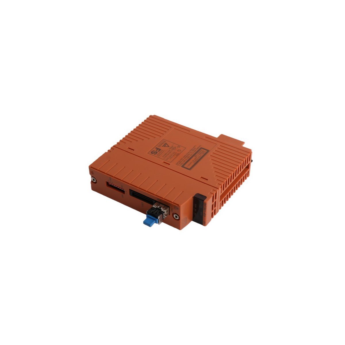
The Emerson DeltaV™ KJ4010X1-BG1 (part number 12P0830X072 / 12P1867X012) is a Localbus Right Extender module belonging to the DeltaV M-series I/O Subsystem. It functions as a physical and electrical bridge on the hardware backplane, allowing the passive expansion of the internal Localbus to a subsequent row of I/O carrier rails.
This module enables seamless scaling of the Distributed Control System (DCS) architecture to accommodate additional I/O modules and communication interfaces without introducing communication lag or signal degradation.
Hardware Specifications
Parameter
Specification
Model Number
KJ4010X1-BG1
Part Number(s)
12P0830X072 / 12P1867X012
Manufacturer
Emerson Automation Solutions
Product Range
DeltaV M-series I/O Subsystem
Module Type
Localbus Right Extender
System Category
Distributed Control System (DCS) Component
Physical Weight
0.15 kg (0.33 lbs)
Physical Dimensions
16.8 x 4.2 x 4.4 cm
Discontinuation Date
December 31, 2018 (Legacy / Replacement Support)
HS Code
8537101190
Localbus Extension Architecture
Within a DeltaV M-series chassis configuration, a single carrier controller slot can natively address a specific span of local I/O modules. When the horizontal physical limit of a single enclosure or mounting rail is reached, the Localbus must be extended down to a new rail segment.
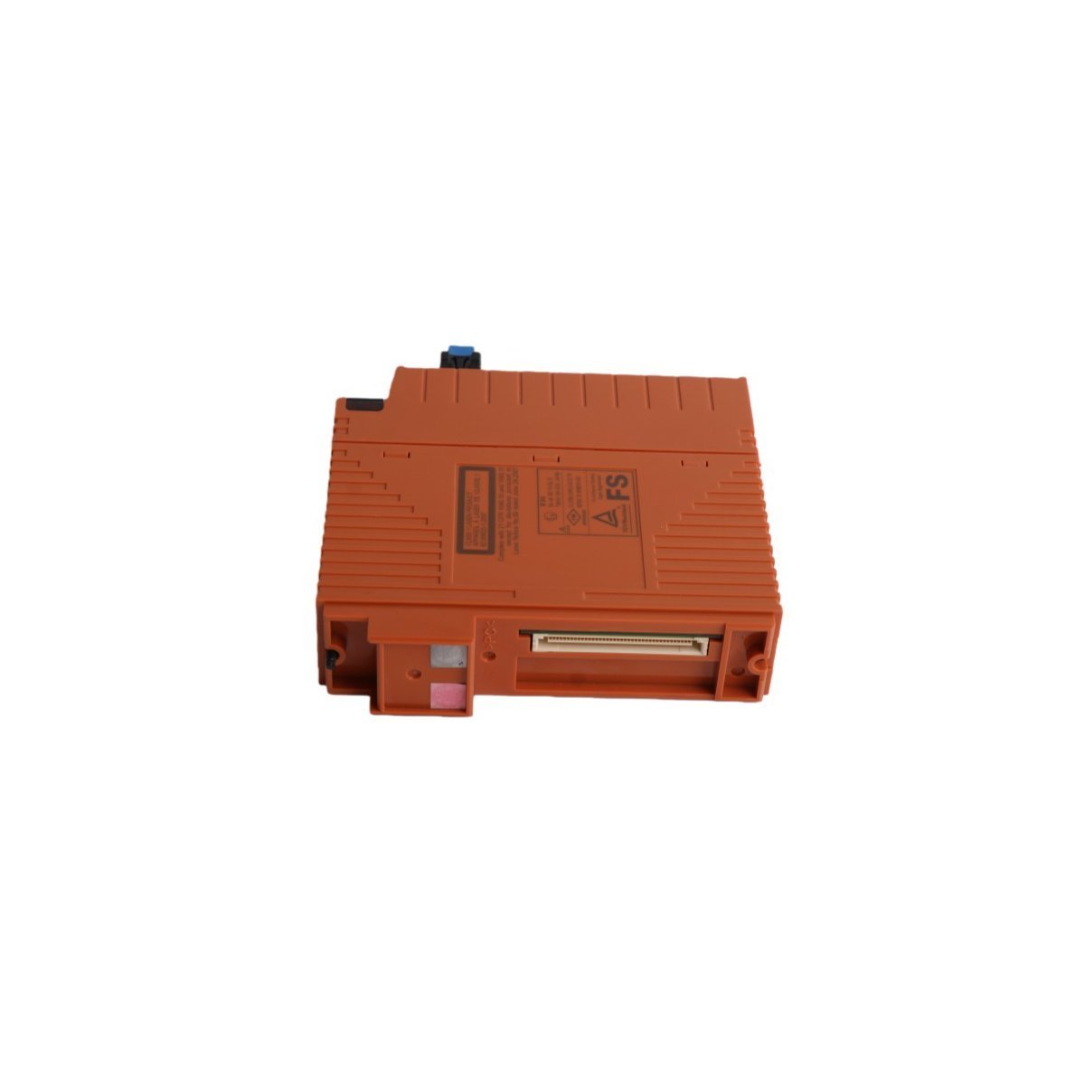
The KJ4010X1-BG1 snaps onto the rightmost edge of the sending carrier rail. It interfaces with a corresponding Left Extender module on the subsequent rail segment via an external, shielded expansion cable, maintaining signal integrity over the expanded physical distance.
Key Architectural Characteristics
Transparent Signal Routine: The module acts as a passive-pass-through buffer. To the DeltaV controller firmware, modules residing on the extended rail appear natively on the local bus scan without requiring complex router parameters or subnet configurations.
Industrial Hardening: Constructed with robust internal trace insulation to withstand the high vibrations, electronic noise (EMI), and wide temperature swings typical of heavy process environments like oil refining, chemical processing, and power generation.
Frequently Asked Questions
Q: Does the KJ4010X1-BG1 require a separate software license or configuration within DeltaV Explorer?
A: No. The Right Extender is an unmanaged physical layer infrastructure piece. It does not occupy a software node address or require explicit configuration in the DeltaV Explorer system tree. It automatically enables the controller to sense the additional slots on the next rail section.
Q: Can this module be unplugged or hot-swapped while the process line is actively running?
A:No. Unplugging a Localbus Extender while the system is powered will instantly drop communication to all I/O modules downstream on the extended carriers. This will trigger an immediate “Bad Status” condition on those channels, likely causing the master controller to command safety interlock states or process shutdowns.
Field Installation Guidelines
Remove Main Power: Shut down power to the entire carrier assembly rack section before attaching or removing expansion hardware to eliminate any risk of short circuits across the backplane pins.
Mount to Rail: Guide the module onto the rightmost position of the M-series carrier interface. Press straight back vertically until the mechanical DIN rail retention clip clicks firmly into place.
Inspect Pins: Ensure that the side-plane male plug on the extender mates squarely with the female receptacle of the adjacent I/O slot module.
Secure Expansion Cable: Insert the certified DeltaV bus expansion cable into the front face plug of the KJ4010X1-BG1. Tighten the integrated retaining thumb screws to guarantee a secure, vibration-resistant connection.
Establish Shield Grounding: Verify that the cable’s outer shield drain wire connects properly with the carrier rail ground to suppress industrial high-frequency interference.
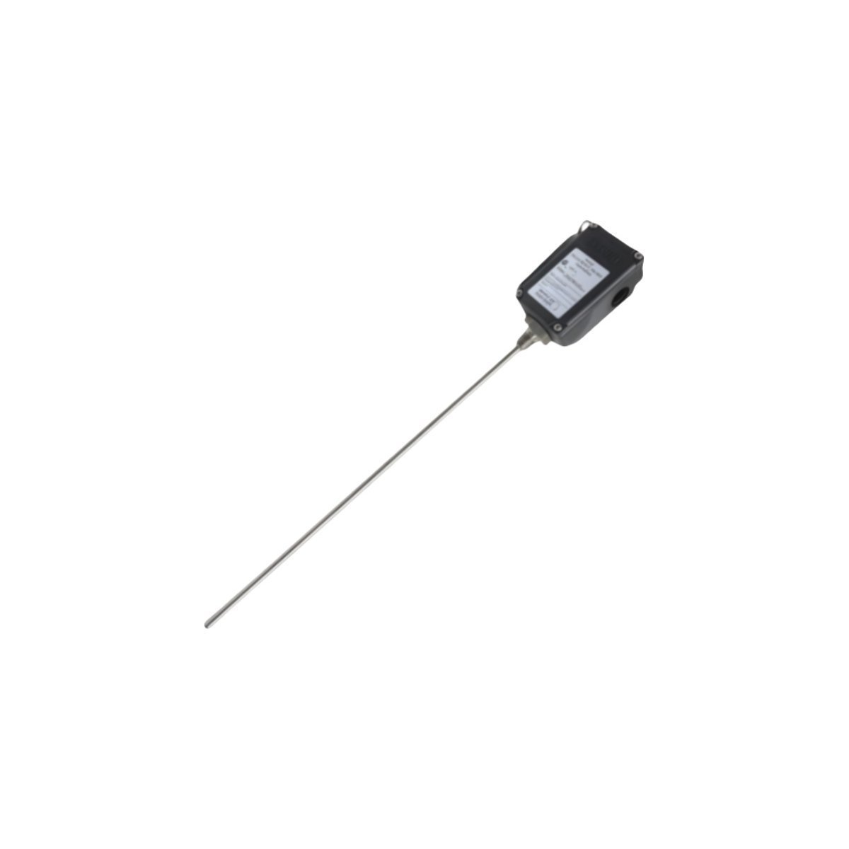
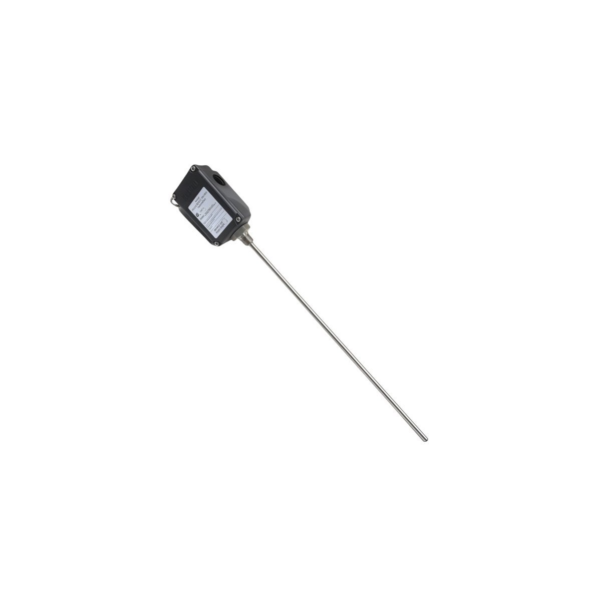
Purchase your Bently Nevada 31000-26-05-00-100-03-02 Proximity Probe Housing Assembly. Authentic product, Brand New factory stock with Global Shipping options available. Request a formal quotation.
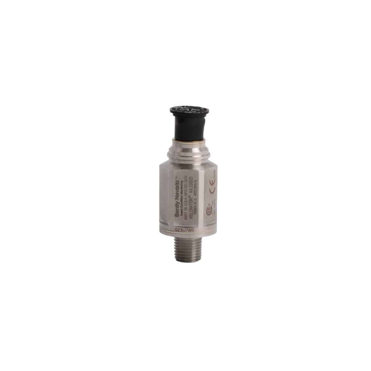
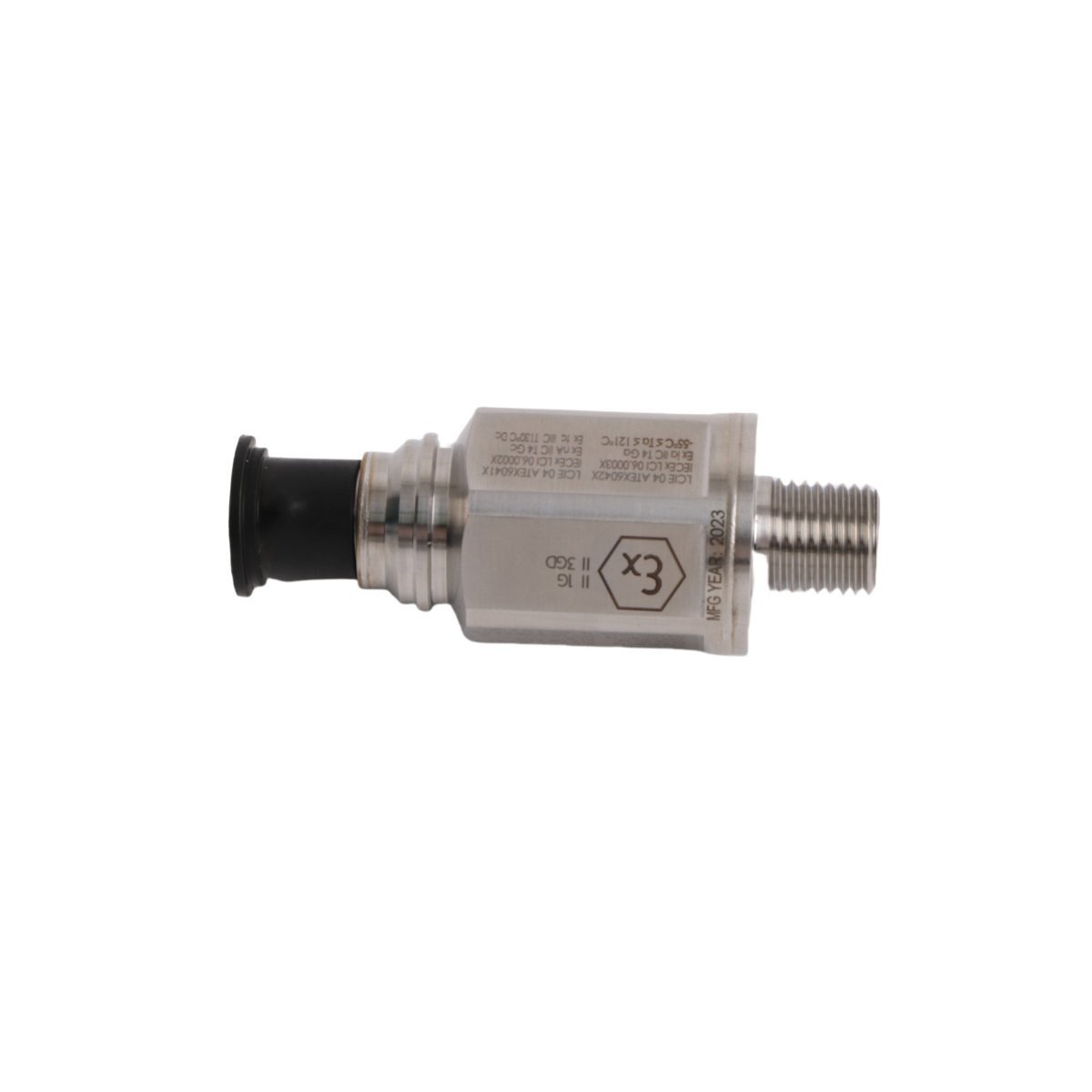
Procure the Bently Nevada 330525-10 Velomitor XA Extended Application velocity sensor for structural condition monitoring loops. Features a ruggedized 316L stainless steel body, IP65 protection, and a 1/2-20 UNF threaded stud. Brand new factory-sealed units available in stock. Request a technical quote today.
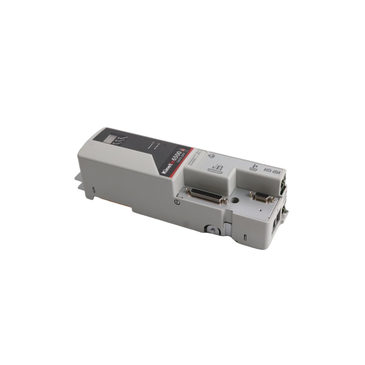
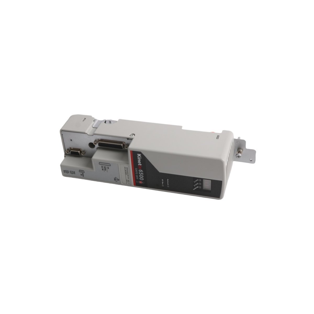
The Allen Bradley 2094-EN02D-M01-S0 module brings advanced CIP Motion safety and STO to Kinetix 6500 series drives. Brand New, Original Stock, with Global Shipping. Secure your motion control system layout—Request a quote now.
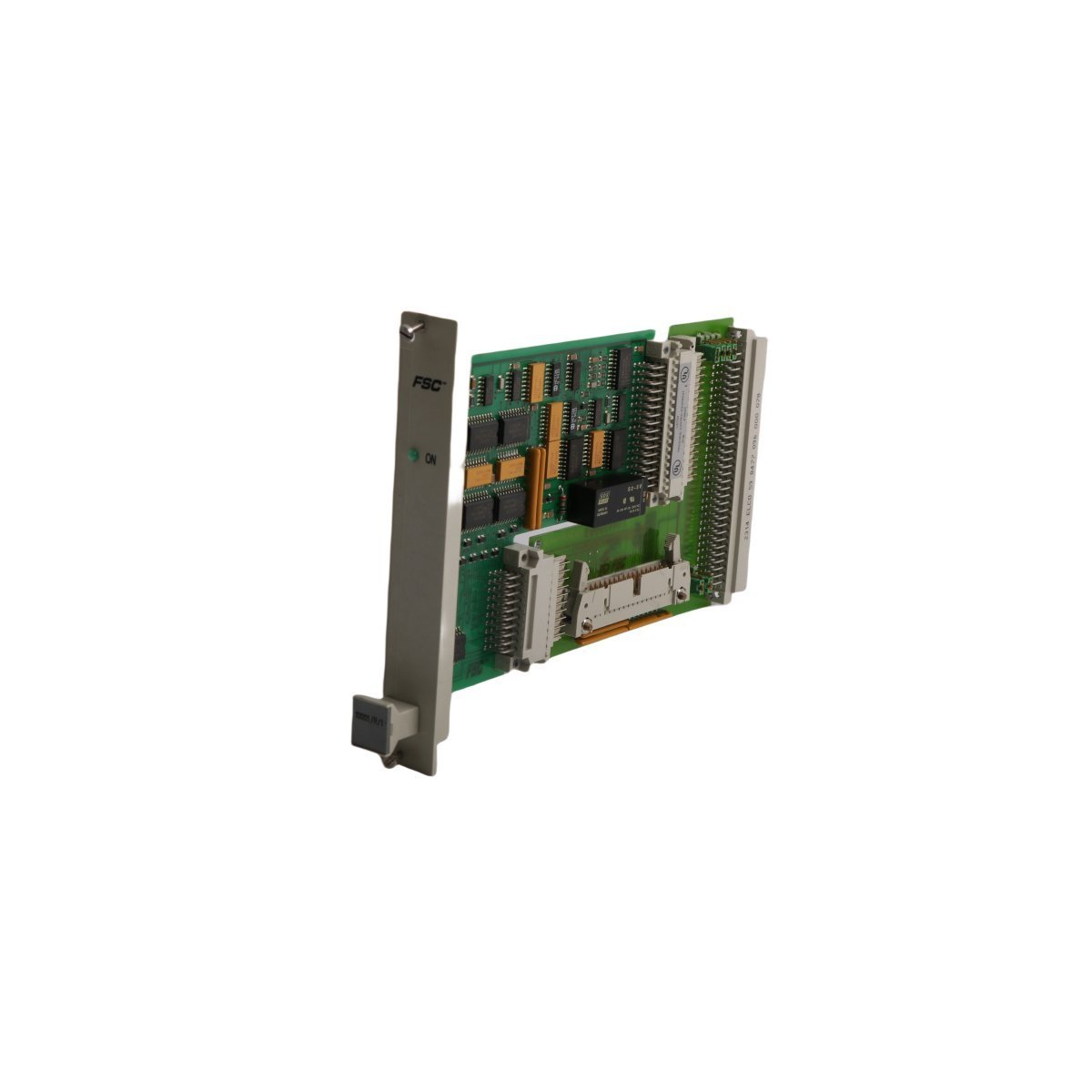
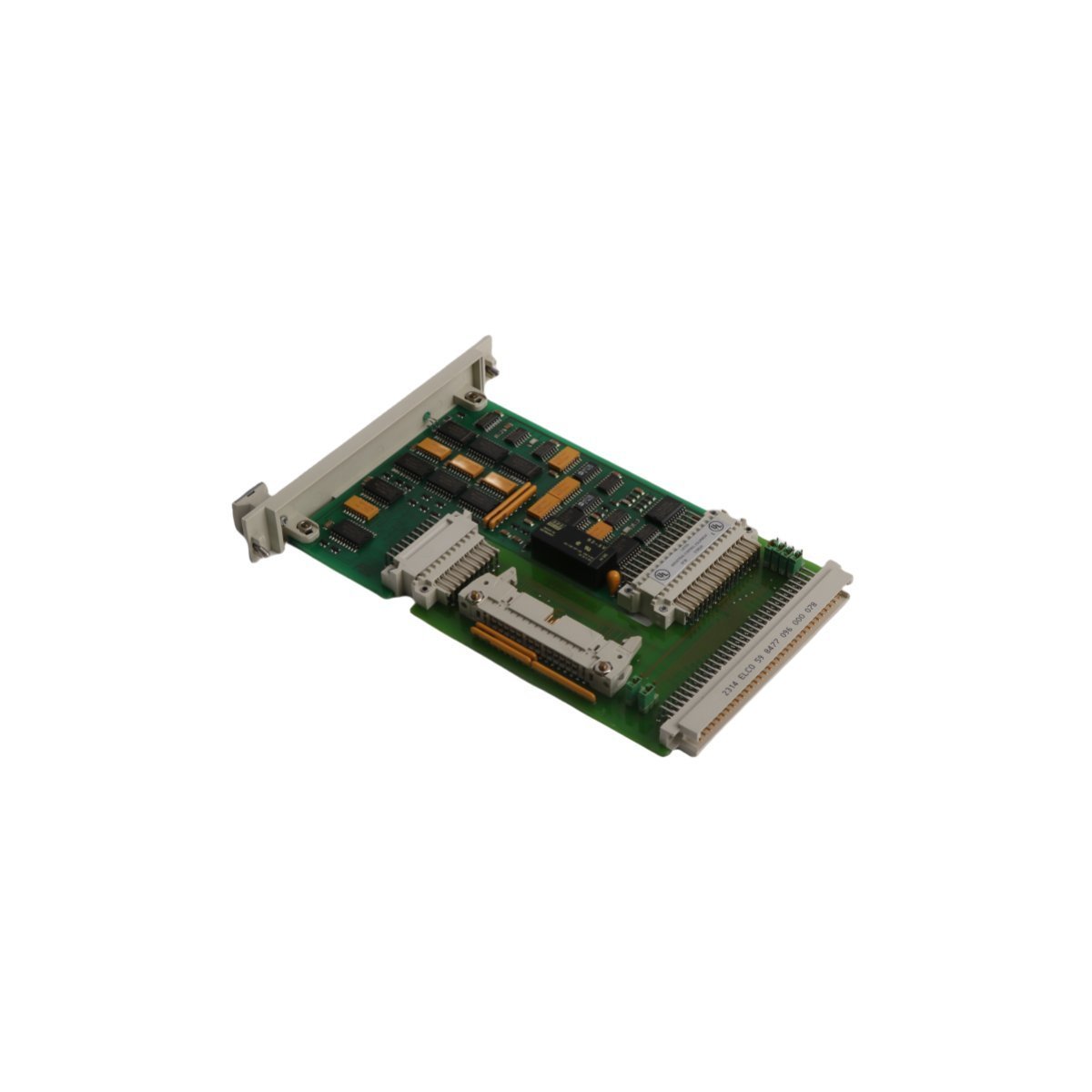
The Honeywell 10001/R/I is a Vertical Bus Driver for the Fail Safe Control (FSC) system. This compact 0.14kg module ensures high-speed data integrity across safety-critical backplanes. Designed for reliability in ESD and SIS applications, it features advanced diagnostics and a rugged USA-manufactured build for demanding industrial environments.
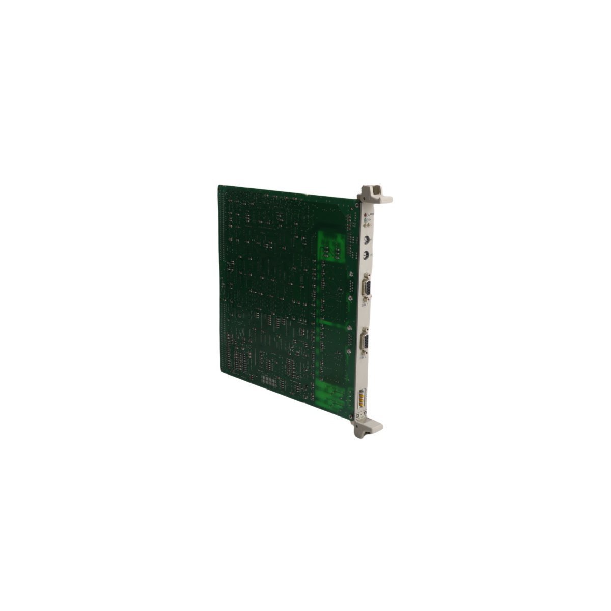
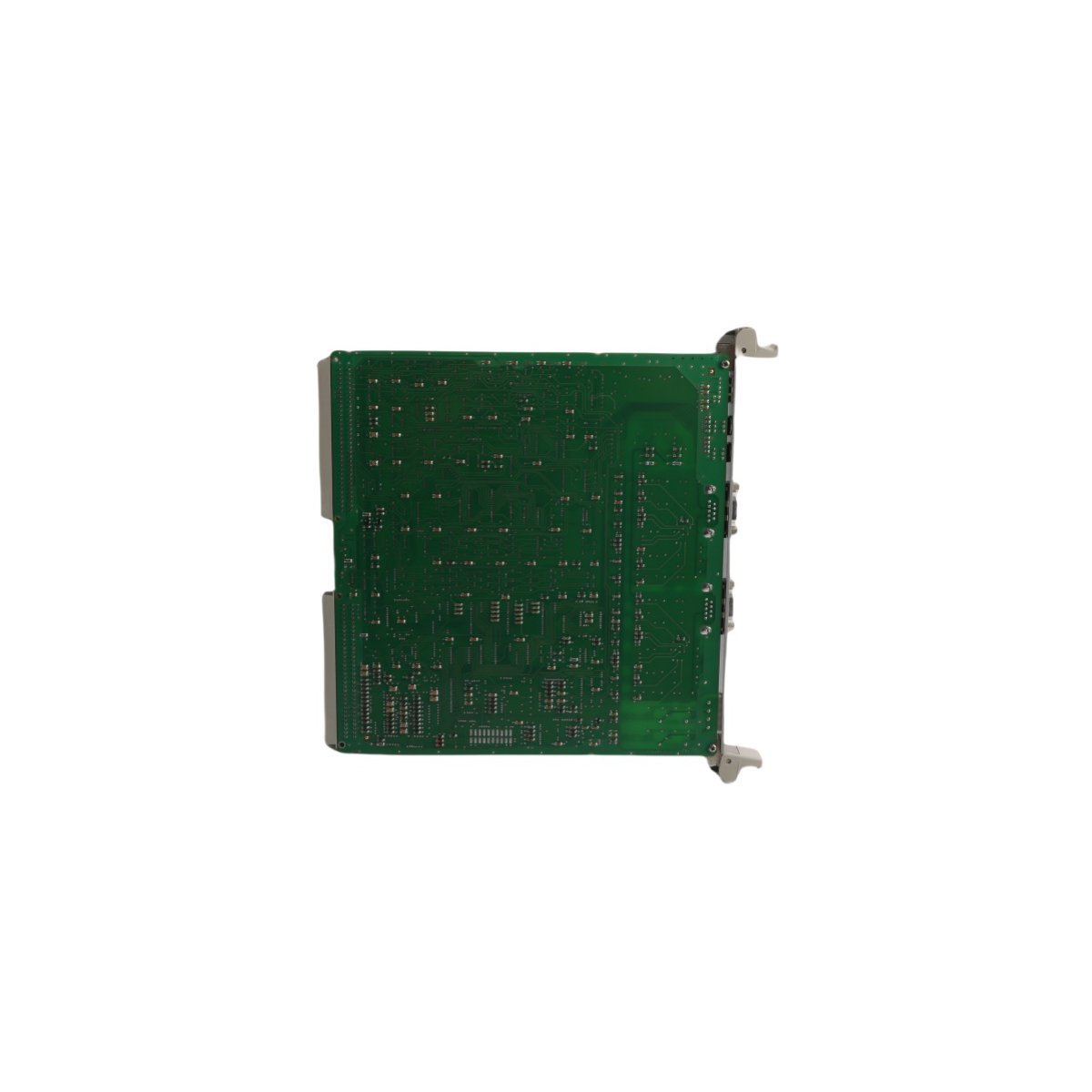
The ABB 3BHT300055R0001 CI-10 is a specialized communication interface board for UNITROL Excitation Systems. It provides robust RS-485 serial connectivity and high-speed data processing to ensure reliable generator control and seamless DCS integration.
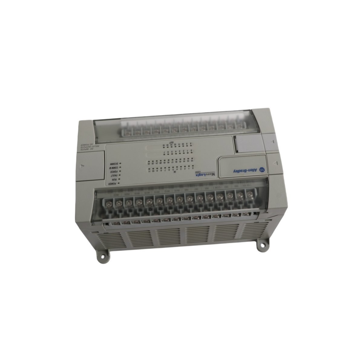
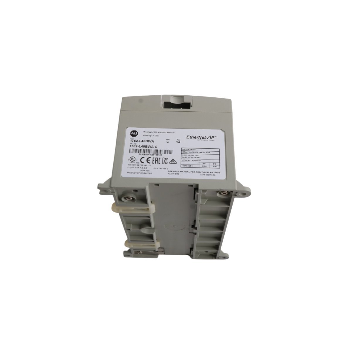
The Allen-Bradley 1762-L40BWA is a 40-point MicroLogix 1200 controller featuring 24V DC inputs and 16 relay outputs. Powered by 120/240V AC, this compact PLC supports high-speed counters and flexible RS-232 communications, making it a reliable solution for sophisticated machine control and industrial automation projects.
The Yokogawa SNT501-13 is a premium Optical ESB Bus Repeater Module designed for long-distance DCS and SIS communication. It supports high-speed 128 Mbps data transfer over fiber optics up to 5 km, providing the EMI immunity and redundancy required for mission-critical industrial automation safety.
The Honeywell 51307038-100 is a dedicated Power Control Module for the Experion PKS series. It provides stable voltage regulation and integrated diagnostic reporting to ensure the reliability of industrial DCS hardware.
The Allen-Bradley MPL-B4560F-SJ72AA is a 460V AC low-inertia servo motor from the Kinetix MP-Series.It features a 3,000 RPM rated speed, a high-resolution optical encoder, and a 130mm frame.Designed for high-speed industrial motion, this brushless motor includes rotatable SpeedTec connectors and a keyed shaft for precise, dynamic automation control.
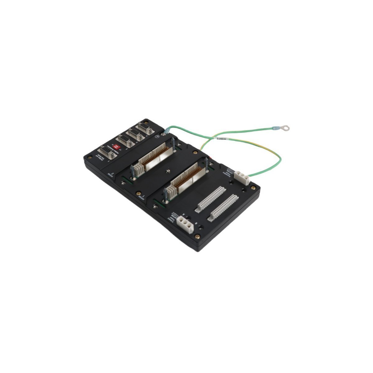
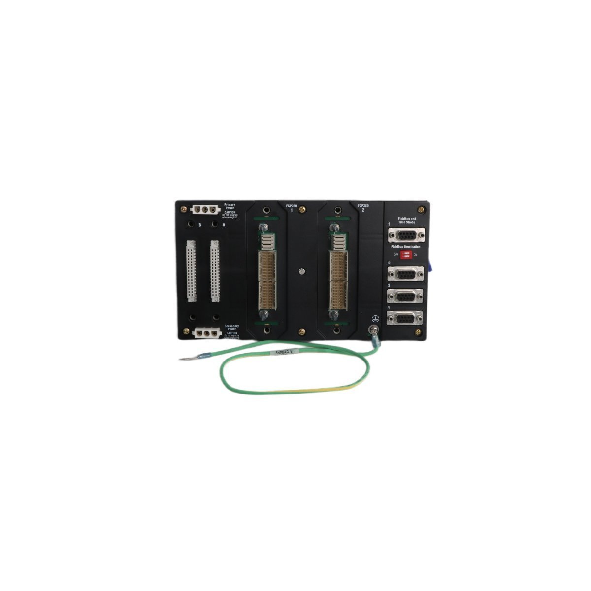
The Foxboro RH924YF is a high-performance DIN-rail mounted baseplate designed for FCP280 processors.This modular unit supports redundant power and high-speed communication, providing a stable and scalable infrastructure for the I/A Series and EcoStruxure DCS.
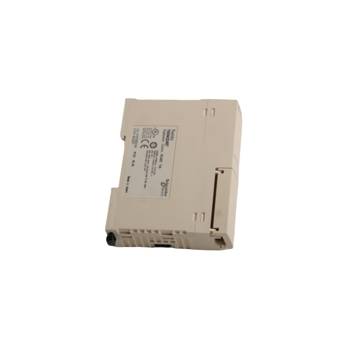
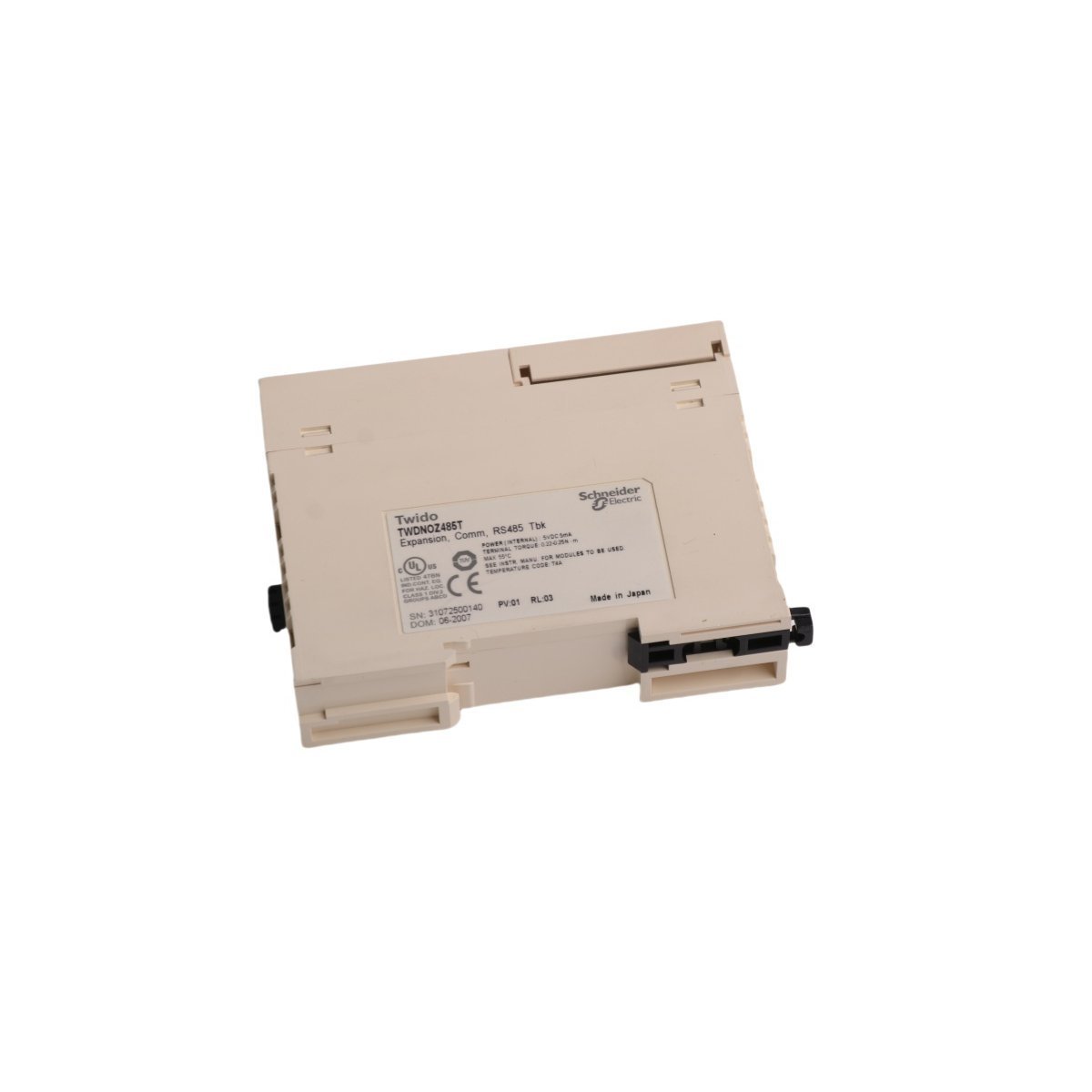
The Schneider Electric TWDNOZ485T is a compact RS485 serial link adaptor specifically engineered for the Twido PLC range. This module enables high-speed Modbus communication and seamless device integration for industrial automation networks.
We are committed to protecting your privacy. The information collected here is strictly used to provide the requested quotes, technical support, and relevant industrial automation solutions.