21000-00-00-00-00-02 Product datasheet
Model number: | 21000-00-00-00-00-02 | | Module Type: | Proximity Probe Housing Assemblies |
Manufacture: | Bently Nevada | | Condition: | Brand New |
Range of Product: | Bently Nevada | | Lead time: | In Stock |
Weight: | 1.08 kg | | HS CODE: | 8537101190 |
Dimension: | 8.5x8.5×30.5cm | | MOQ: | 1 |
Product Origin: | USA | | System: | TSI |
Discontinued on: | active | | Communication Service: | Ethernet router |
21000-00-00-00-00-02 Functional Description
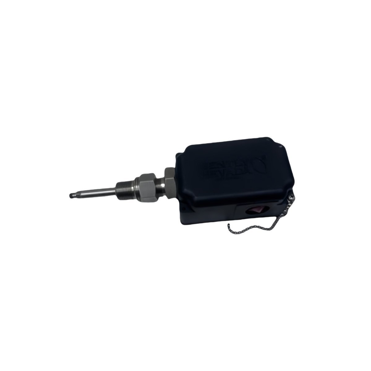
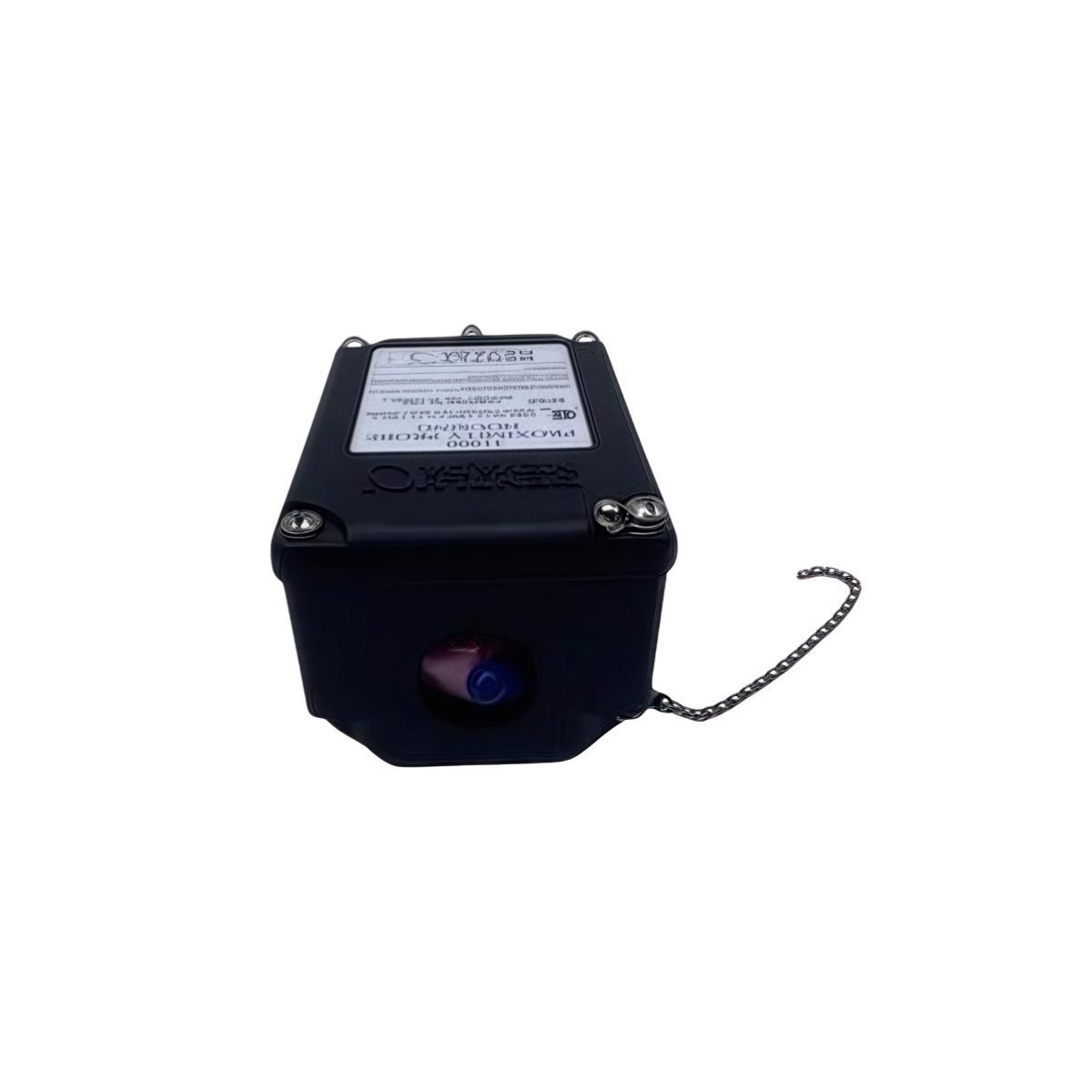
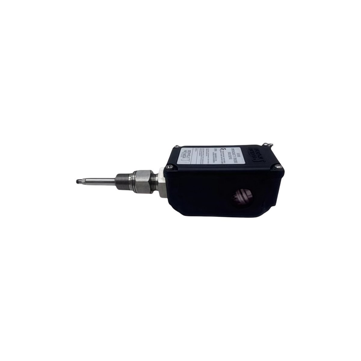
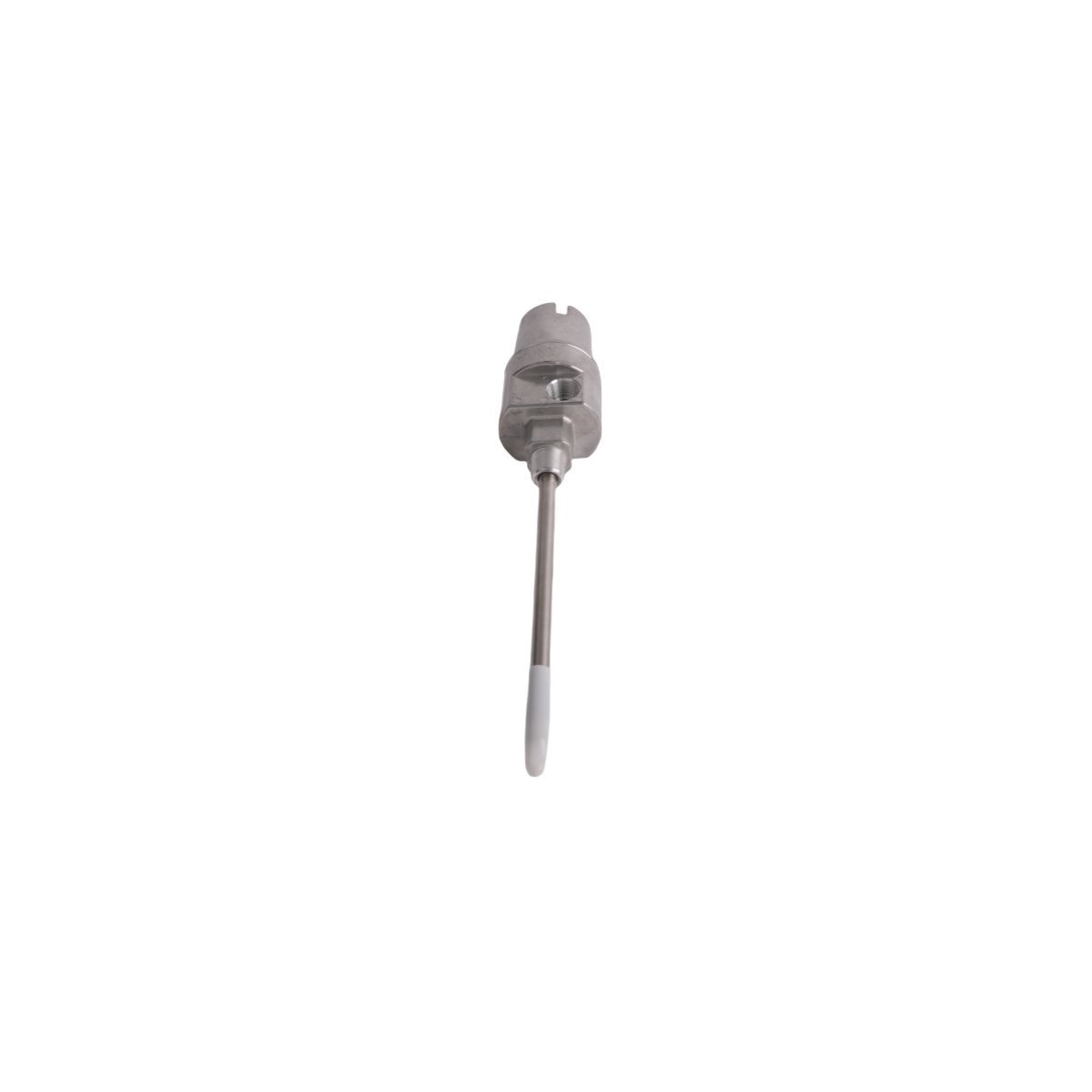
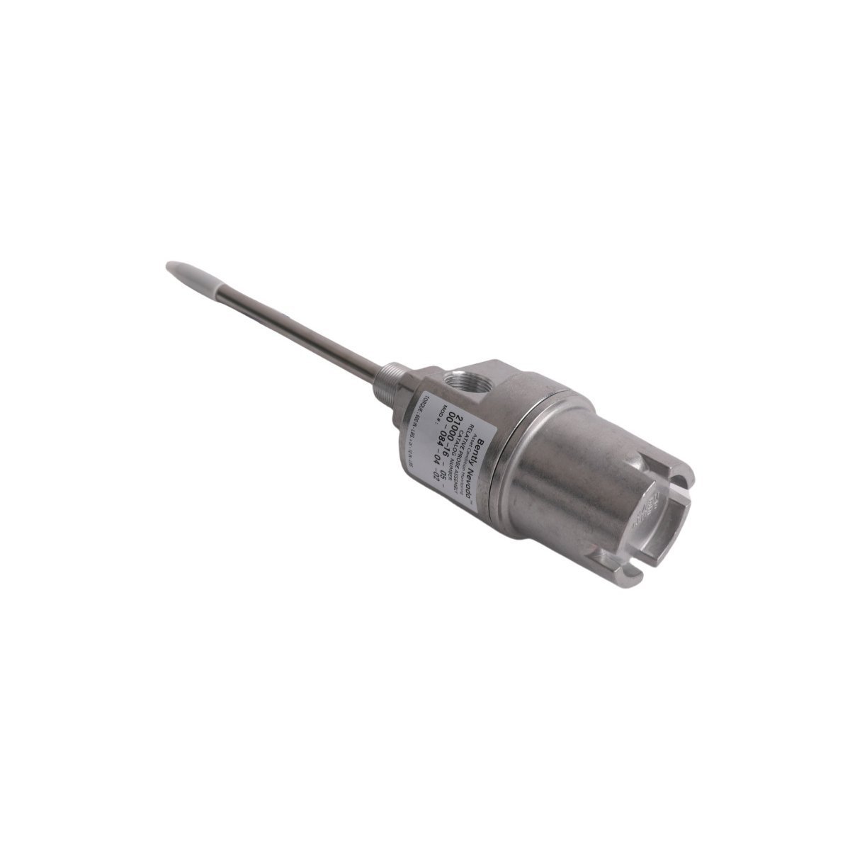
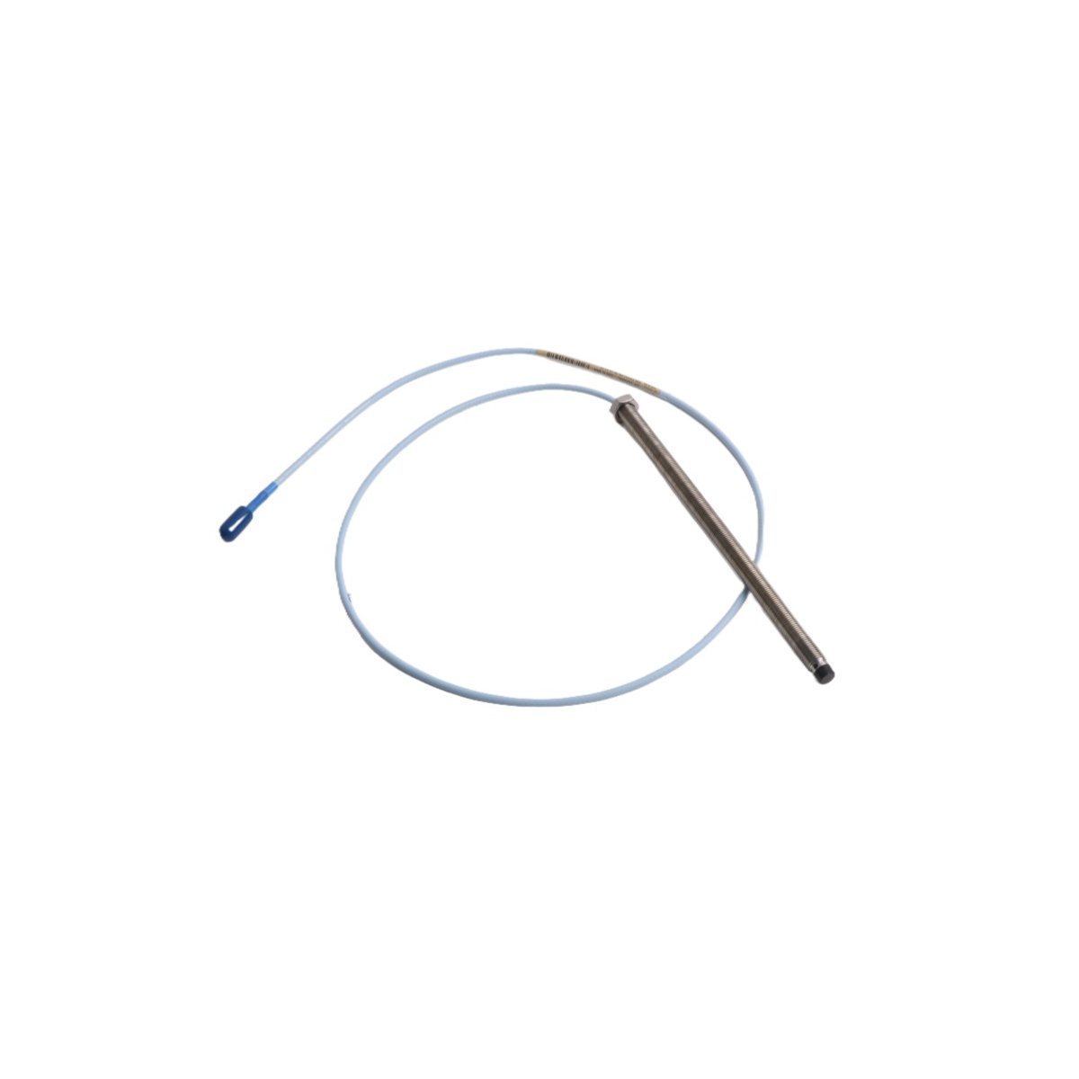
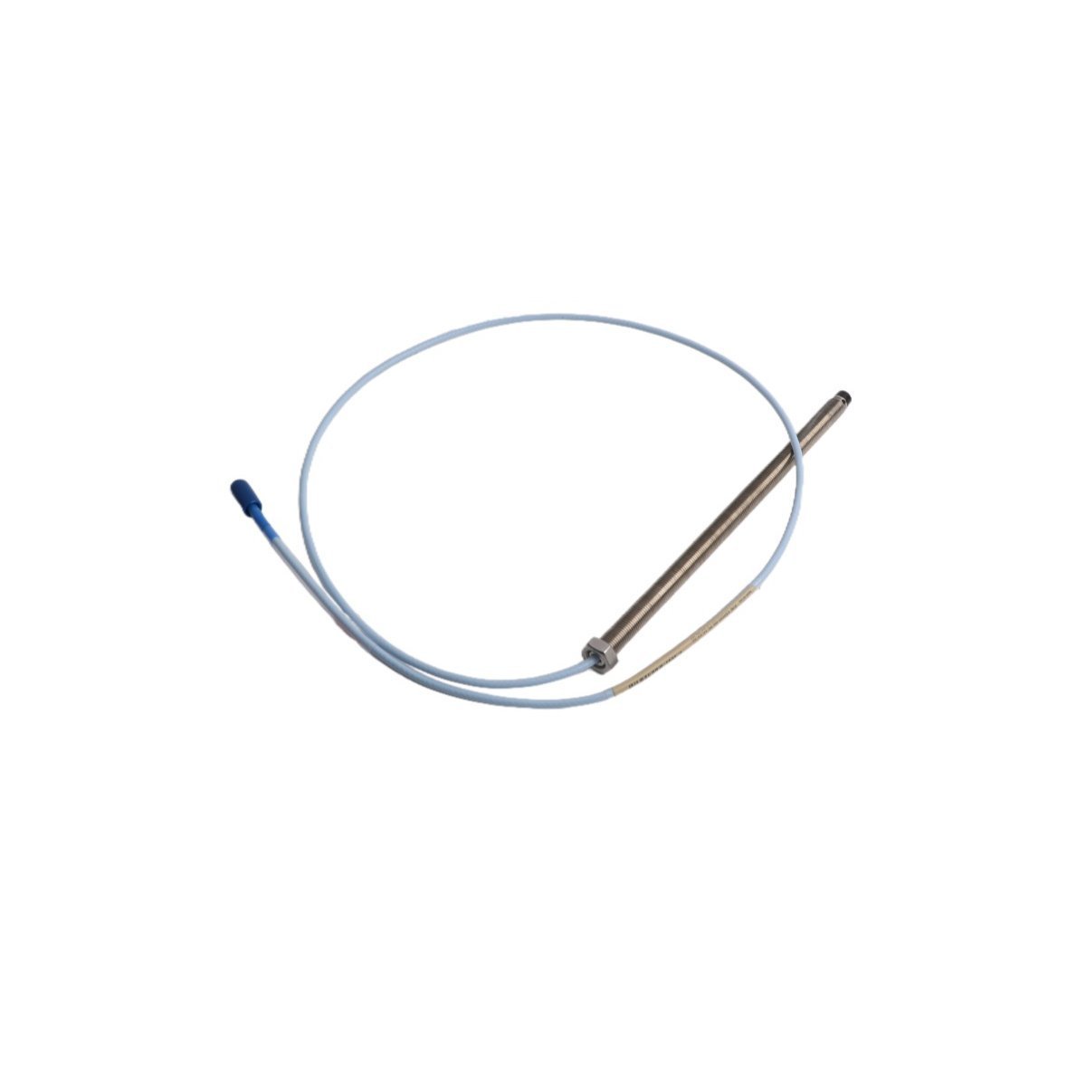
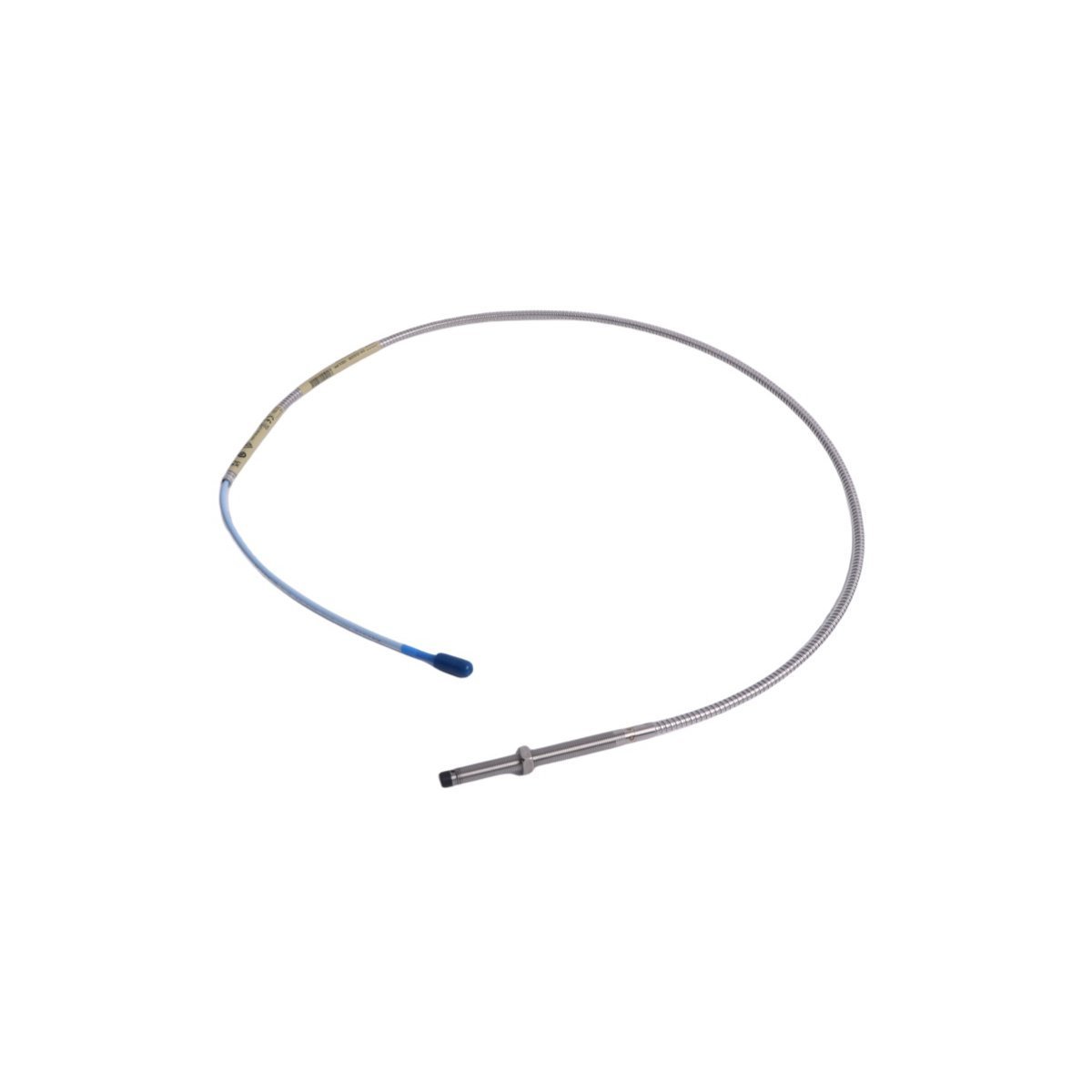
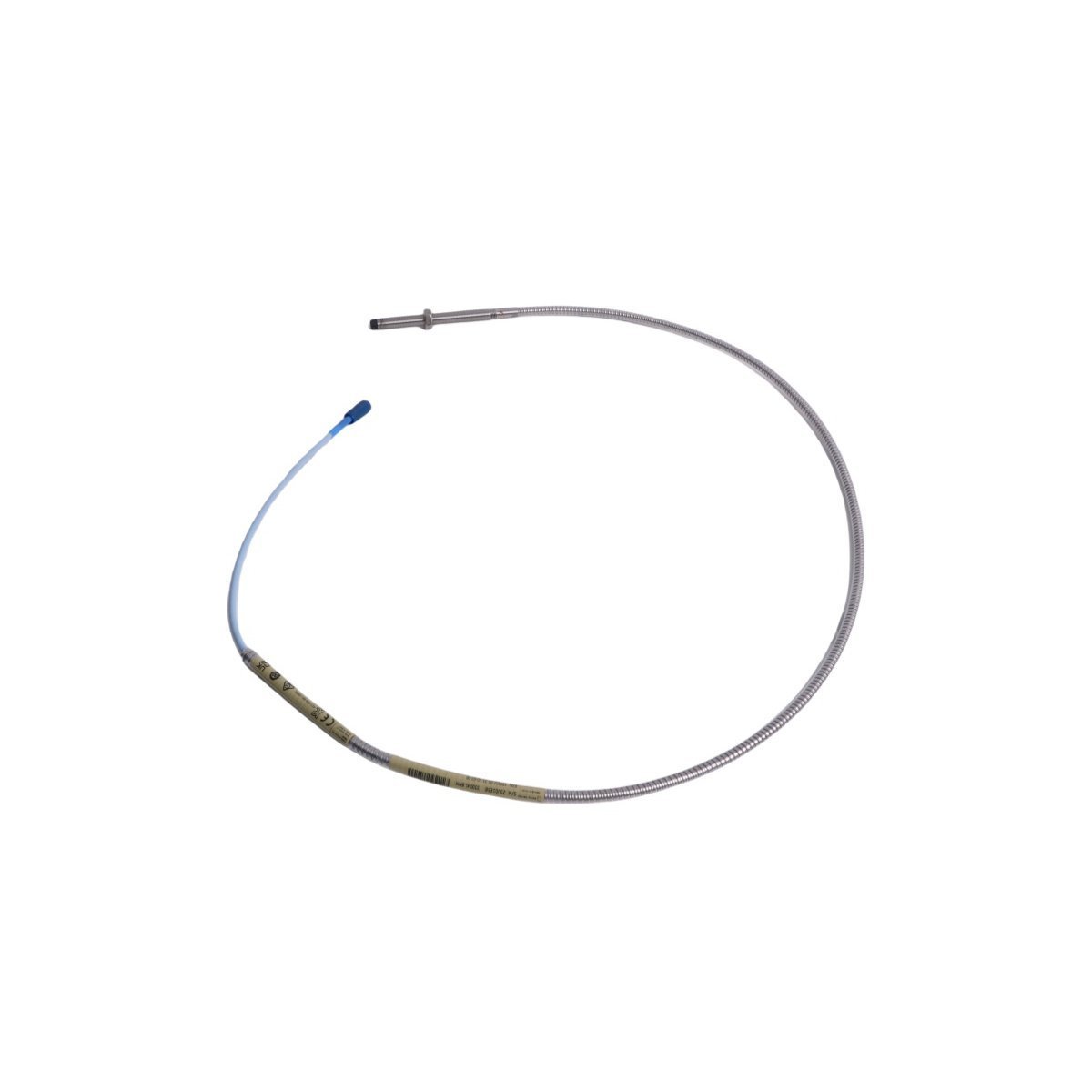
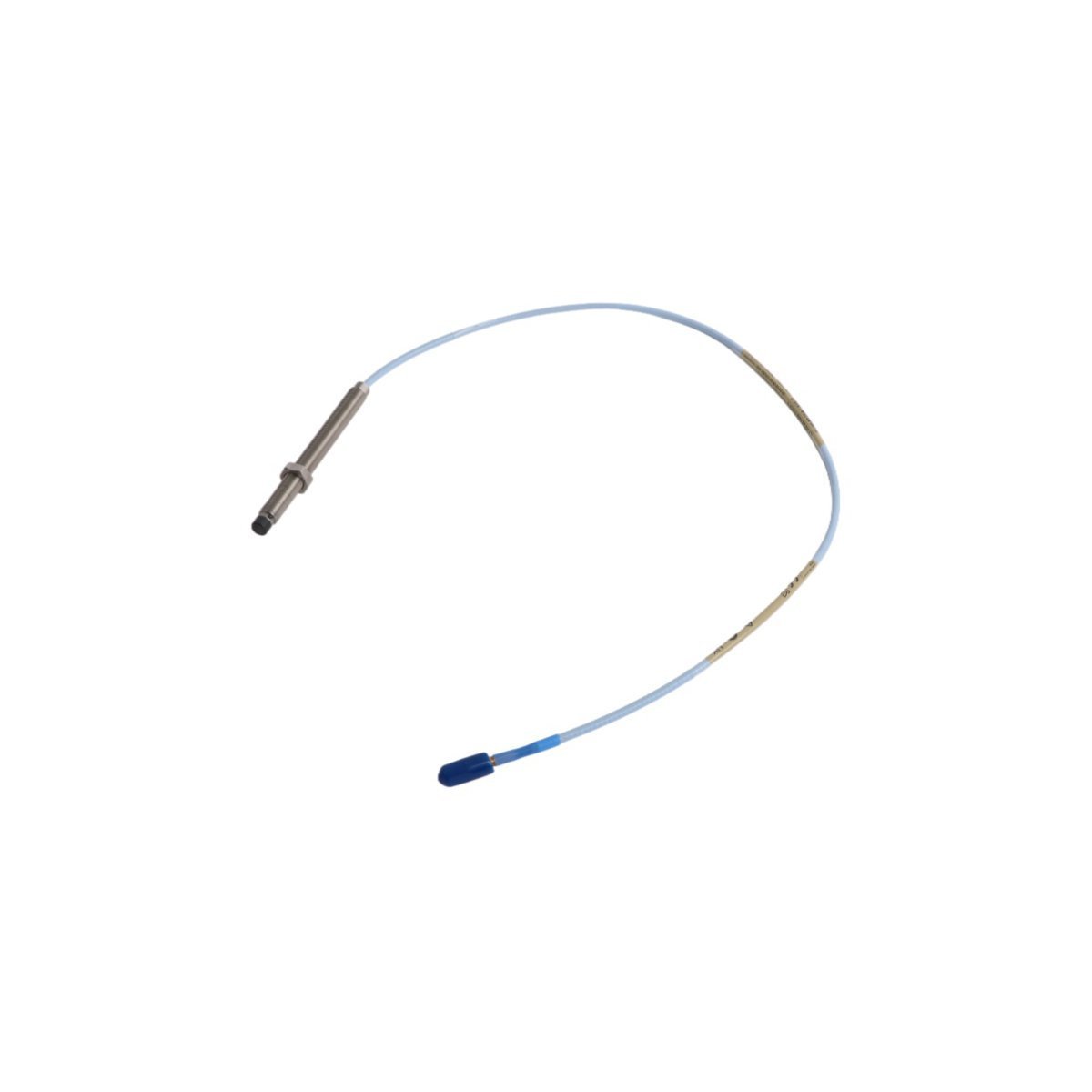
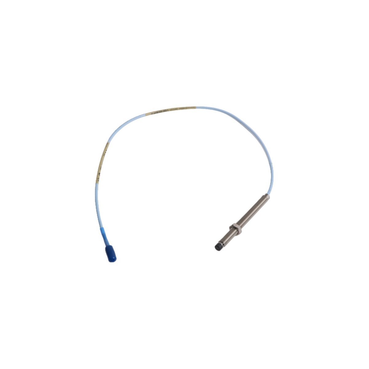
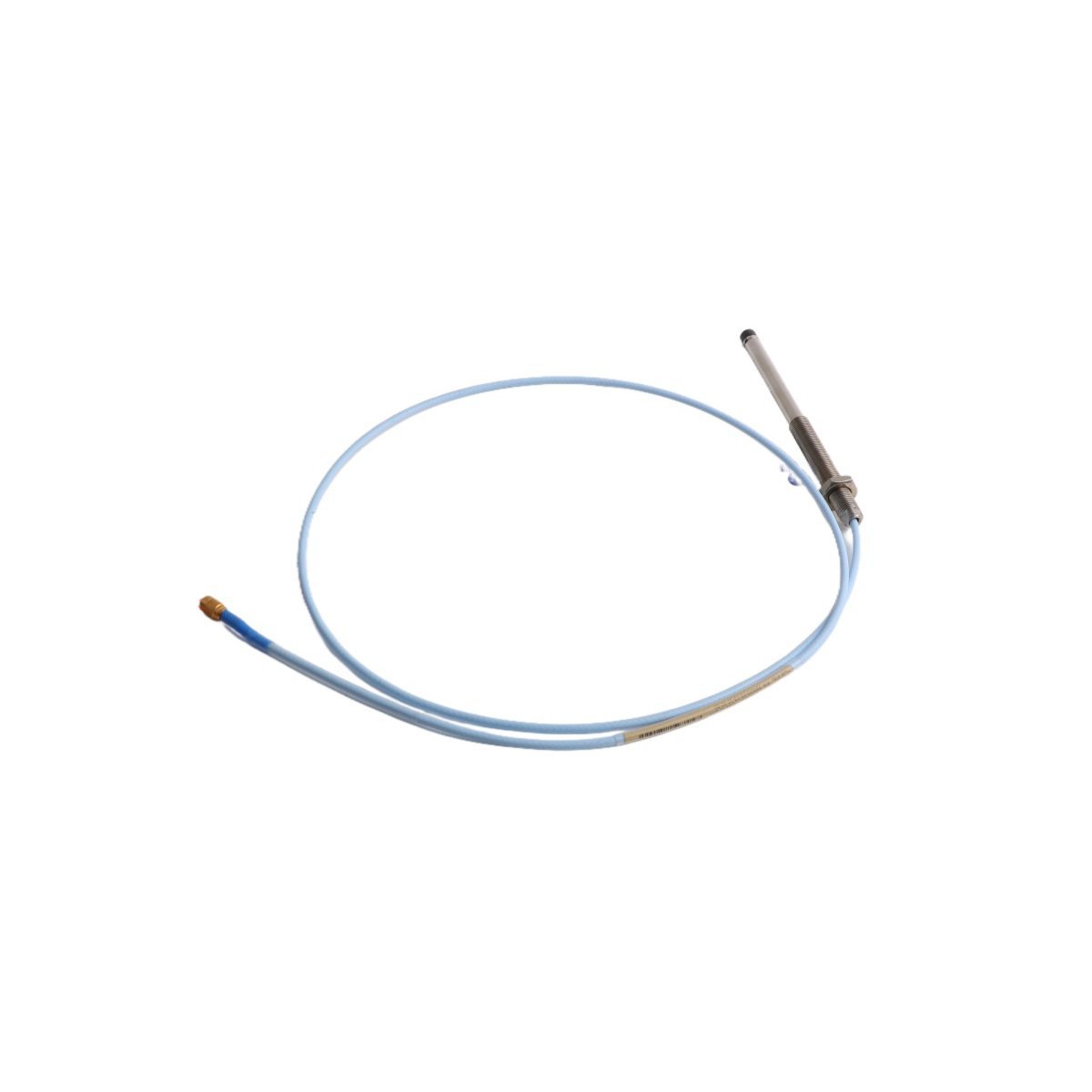
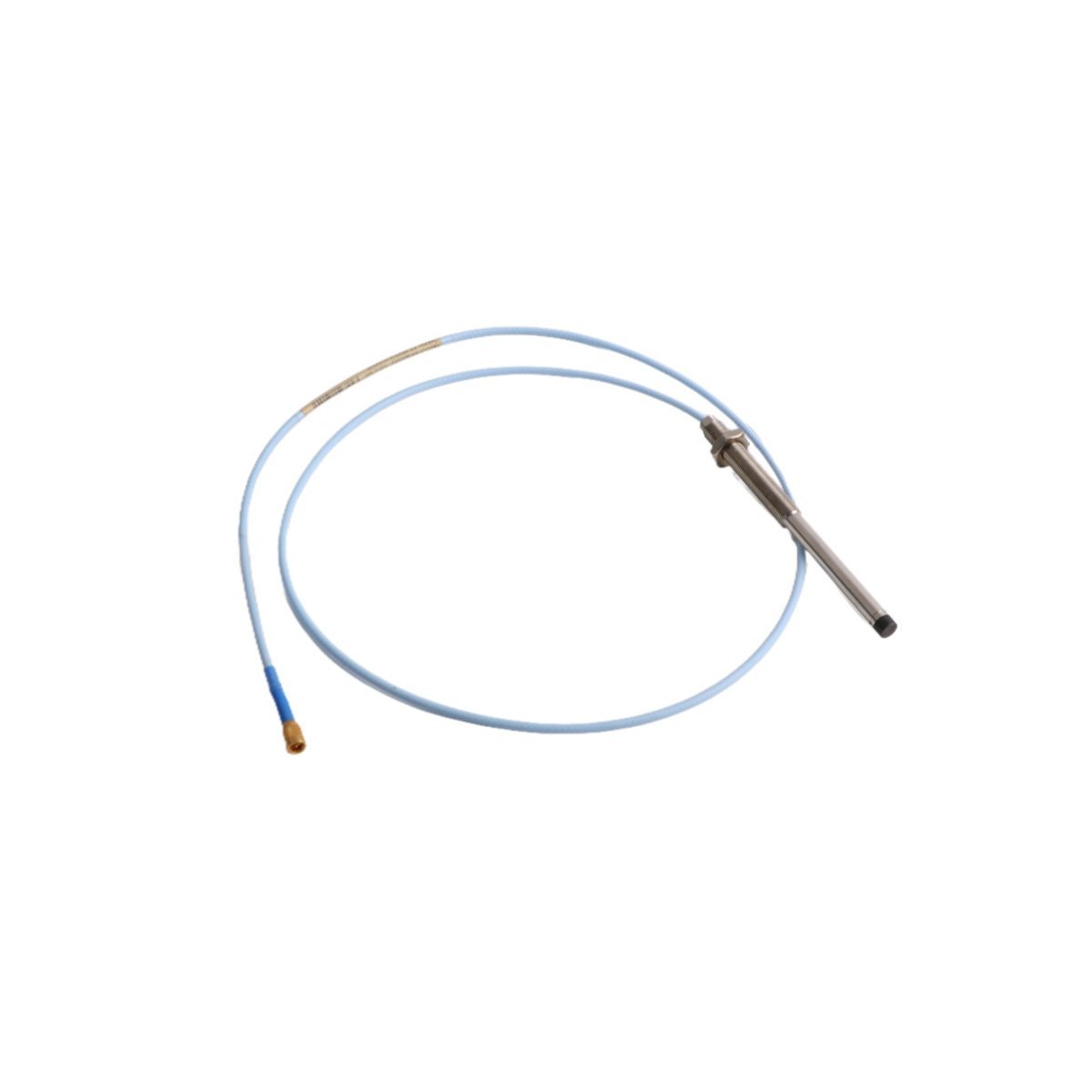
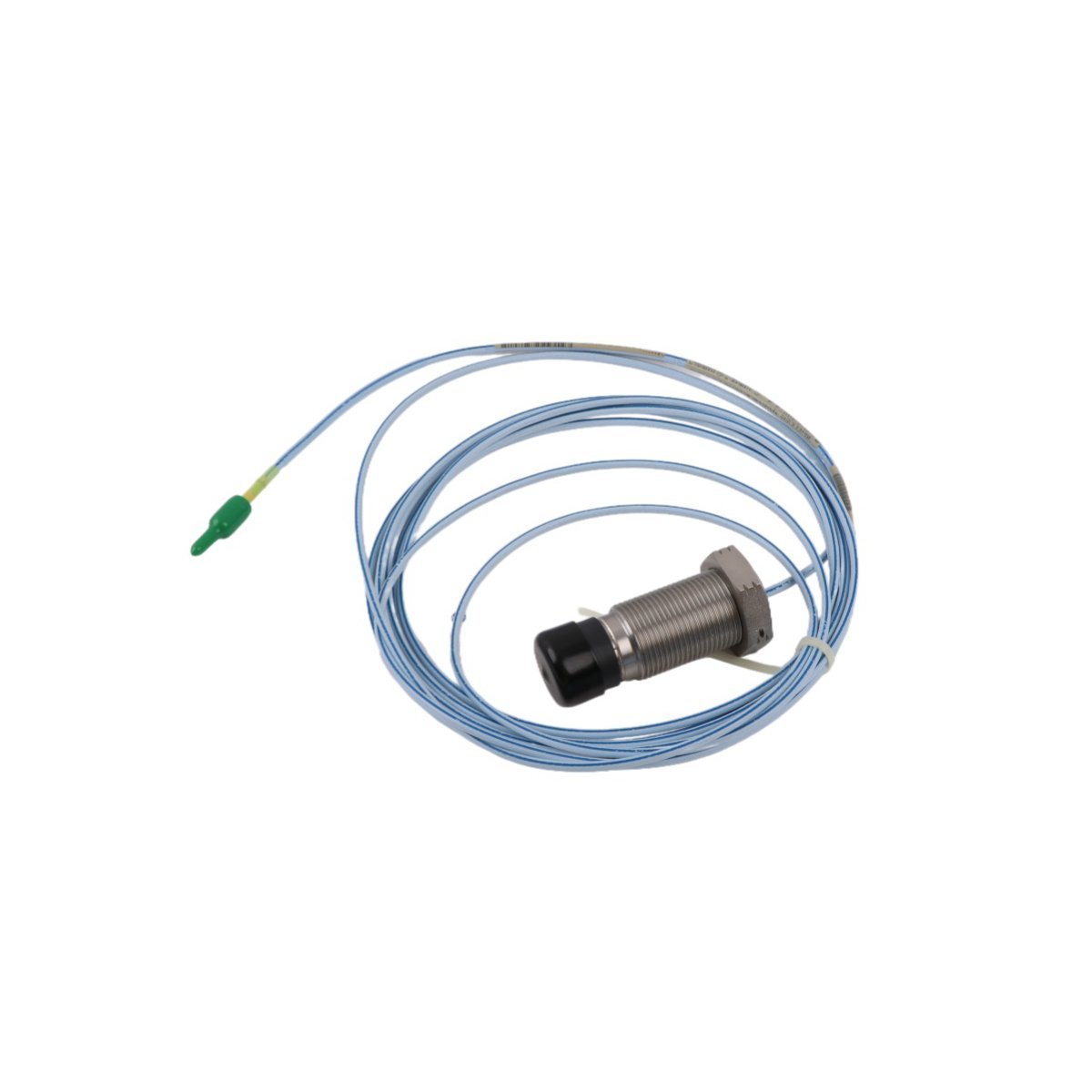
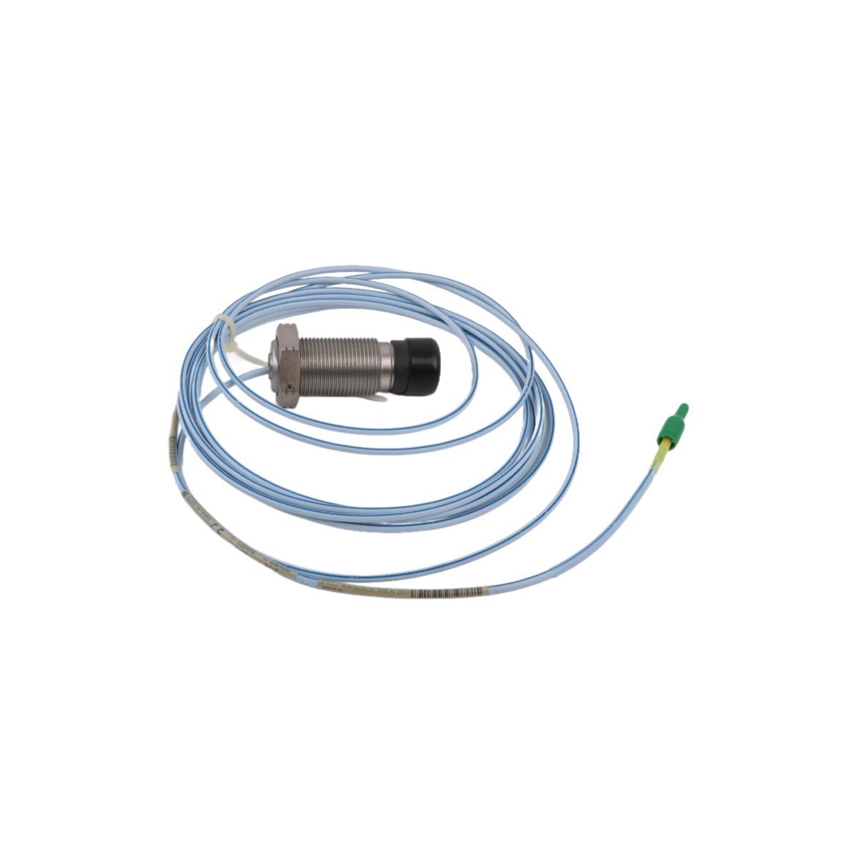
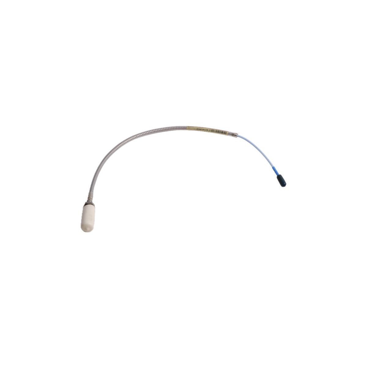
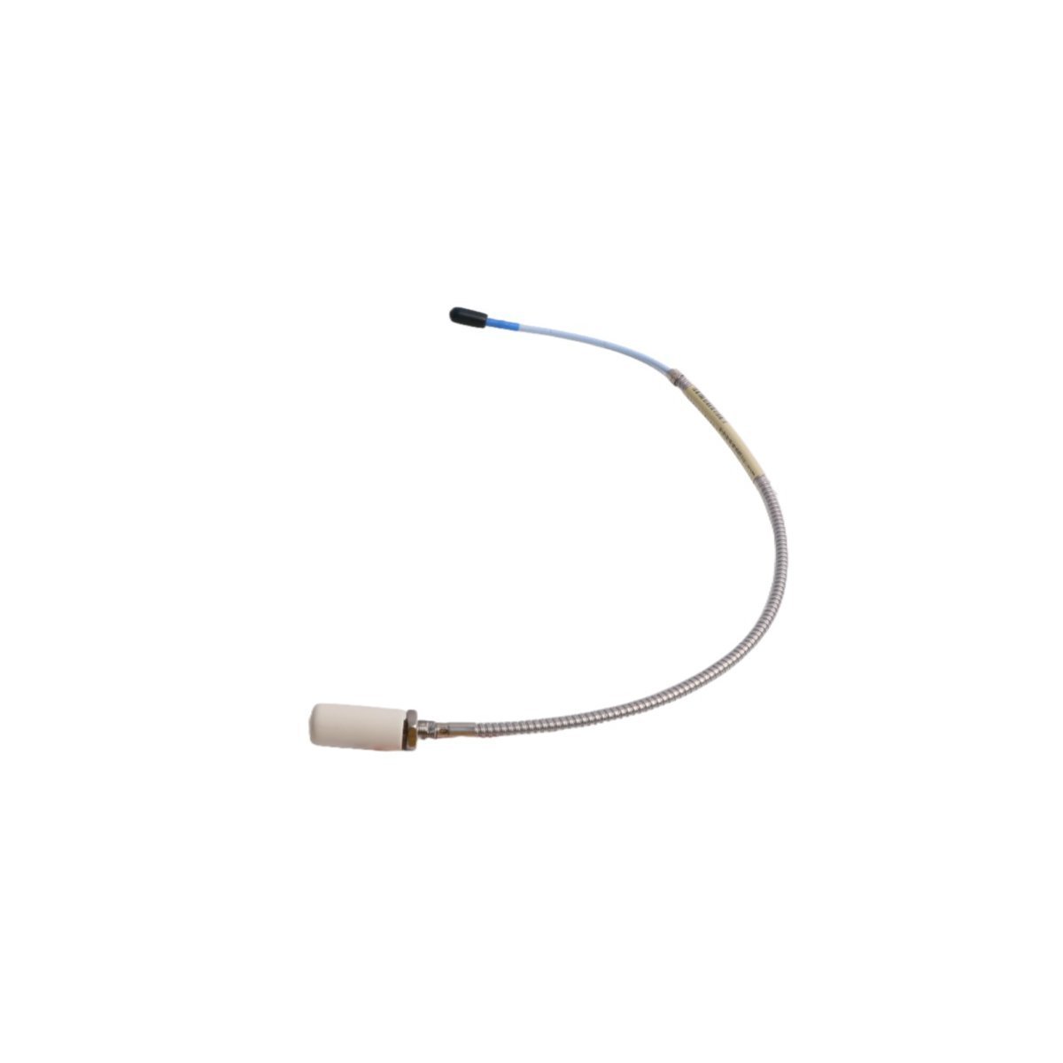
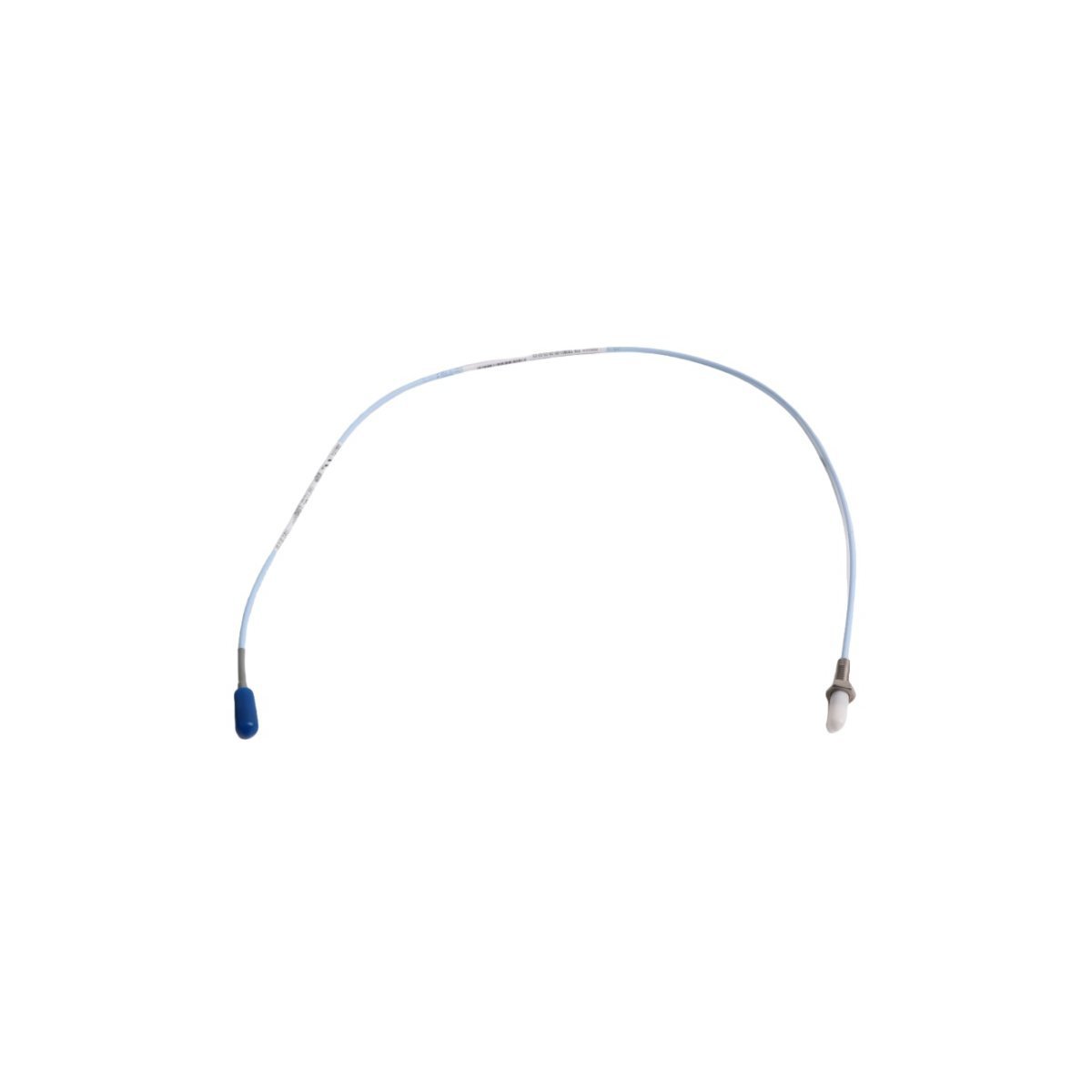
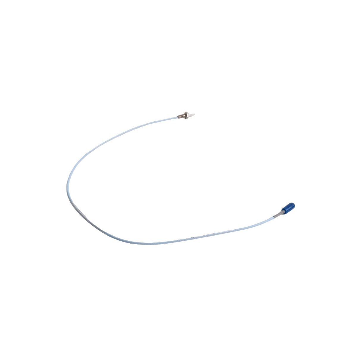
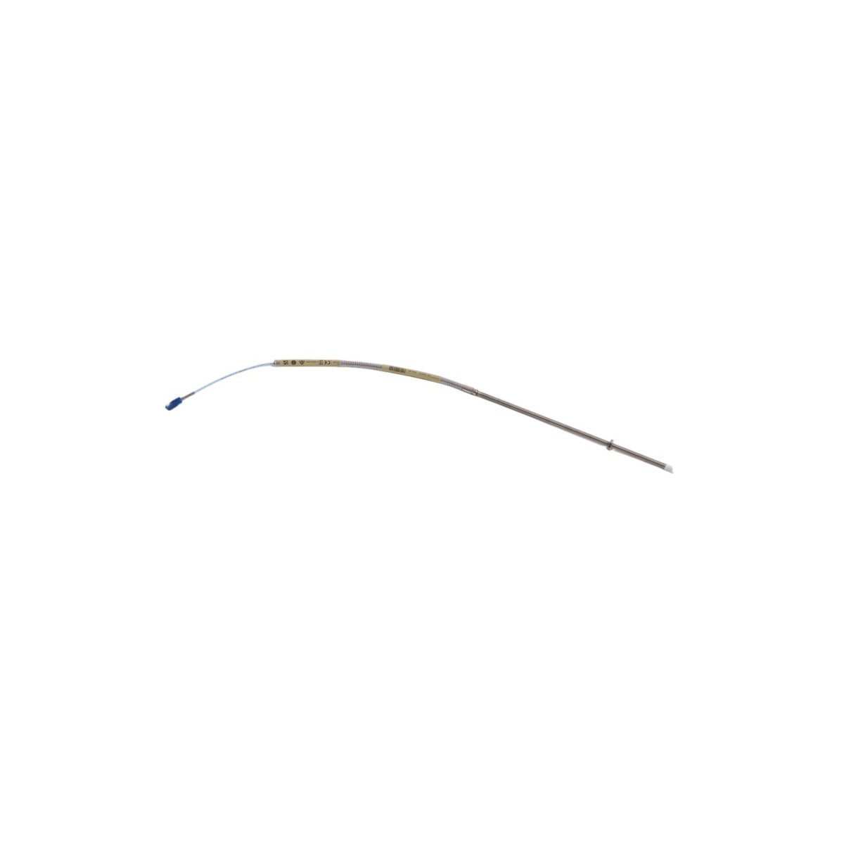
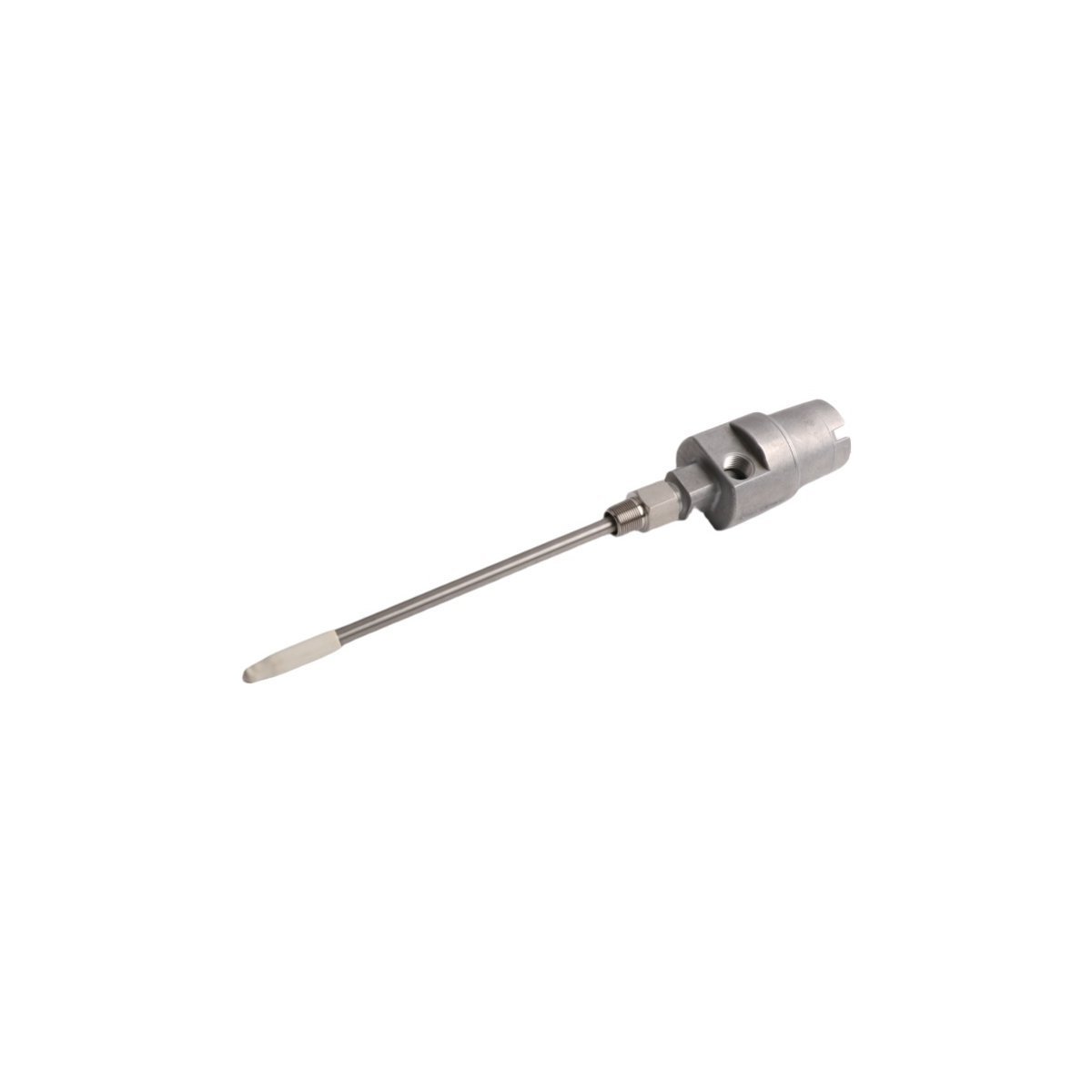
The Bently Nevada 21000-00-00-00-00-02 proximity transducer system delivers reliable shaft vibration and position monitoring for industrial rotating equipment. Designed for demanding environments, this 8mm probe operates across a wide -40°C to +150°C temperature range while maintaining ±1% measurement accuracy. The Bently Nevada 21000-00-00-00-00-02 Proximity Probe Housing Assembliesfeatures a durable 5-meter integral cable and meets stringent hazardous area certifications, making it ideal for critical applications in power generation, oil & gas, and heavy industries.
Engineered for continuous operation, the 21000-00-00-00-00-02 Bently Nevada Proximity Probeprovides essential data for condition monitoring systems to detect early mechanical faults. Its stainless steel construction resists corrosion in challenging environments while ensuring long-term measurement stability. Maintenance teams value the system's consistent performance in high-vibration areas and its compatibility with Bently Nevada's monitoring instrumentation for seamless integration.
The transducer's advanced eddy current technology enables non-contact measurement of shaft position and vibration with excellent repeatability. These capabilities help prevent catastrophic equipment failures in turbines, compressors, and other high-value rotating assets. The system's hazardous area certification (ATEX/IECEx) allows deployment in potentially explosive environments common in refinery and offshore applications.
As part of Baker Hughes' comprehensive machinery protection solutions, the 21000-00-00-00-00-02 Bently Nevada PDFcontinues to set industry standards for reliability and precision. Its combination of rugged construction, accurate measurement, and safety certifications makes it the preferred choice for protecting critical industrial equipment worldwide, ensuring operational continuity and reducing maintenance costs.