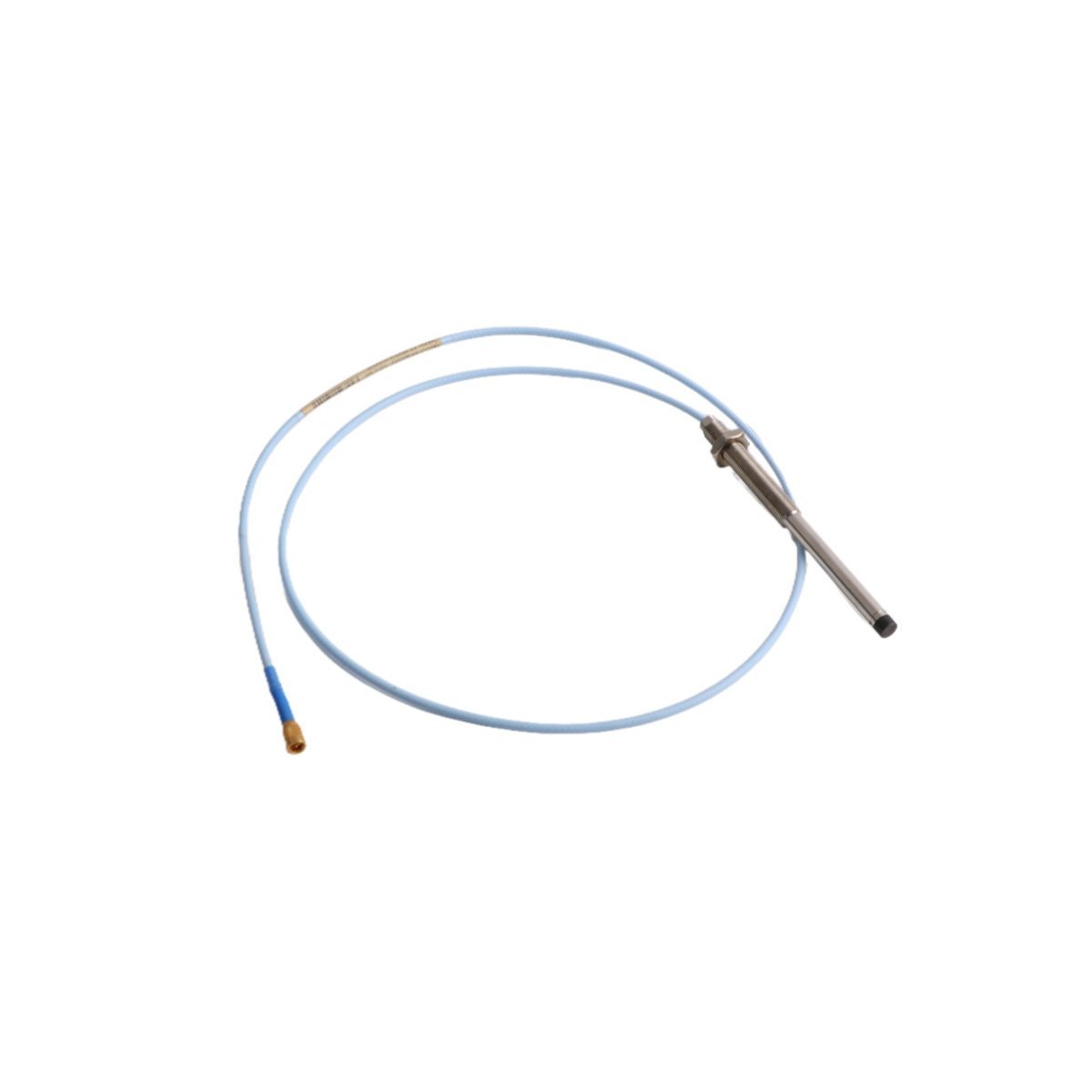
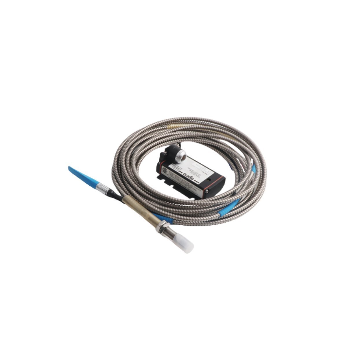
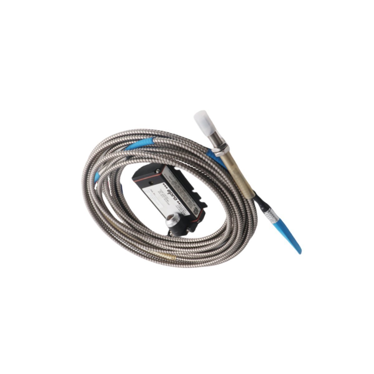
The EMERSON A6210, also cataloged as the A6210 Eddy Current Sensor, serves as the primary A6210 Thrust Position, Differential Expansion, and Rod Position Monitor utilized to execute precise mechanical displacement tracking across CSI 6500 platforms. The module converts analog high-frequency proximity signals from field-mounted eddy-current probes into digital metrics representing shaft axial drift and thermal growth relative to the machine casing.
Hardware Specifications
Parameter
Specification
Model
A6210
Brand
EMERSON
Origin
USA
Weight
0.24 kg
Dimensions
19.0 x 12.8 x 7.0 cm
Operating Temp
Standard industrial cabinet limits (discontinued Dec 31, 2018)
Power Consumption
Internal backplane-derived power consumption boundaries
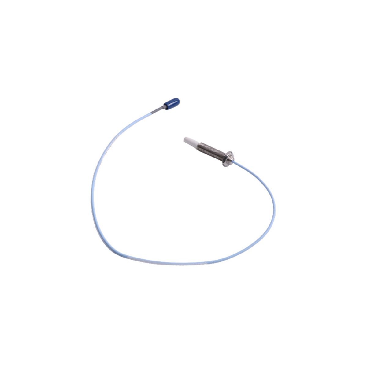
Sensor Interface
Non-contacting eddy-current probe systems
System Platform
CSI 6500 Machinery Health Monitor / DCS
HS Code
8537101190
Mechanical Monitoring & TSI Characteristics
The module interfaces directly with proximity sensor loops where eddy-current probe scaling determines mechanical conversion coefficients. During startup and steady-state thermal phases, the hardware performs gap voltage validation (-10 VDC targets) to verify nominal linear calibration zones. This continuous voltage verification allows the internal logic to monitor rotor dynamics, distinguish mechanical axial shift from cross-talk suppression events, and transmit processed critical limits to the host system network.
Frequently Asked Questions
Q: How is eddy-current probe scaling adjusted within the A6210 module hardware?
A: Scaling parameters and linear range values are not configured via physical jumpers on the card. All calibration configurations, probe selection types, and sensitivity slopes must be downloaded through the CSI 6500 configuration software interface.
Q: What indicates a gap voltage deviation outside the nominal -10 VDC targets?
A: The module executes internal self-diagnostics that drive the channel status to a fault state if the DC bias voltage drifts outside the specified sensor linear operating limits, preventing false thrust position trips.
Field Installation Guidelines
Insert the A6210 module into its designated slot within the CSI 6500 rack assembly, ensuring the backplane connector pins sit completely flush.
Secure the front panel retaining fasteners to lock the module chassis into the structural frame and complete the grounding loop.
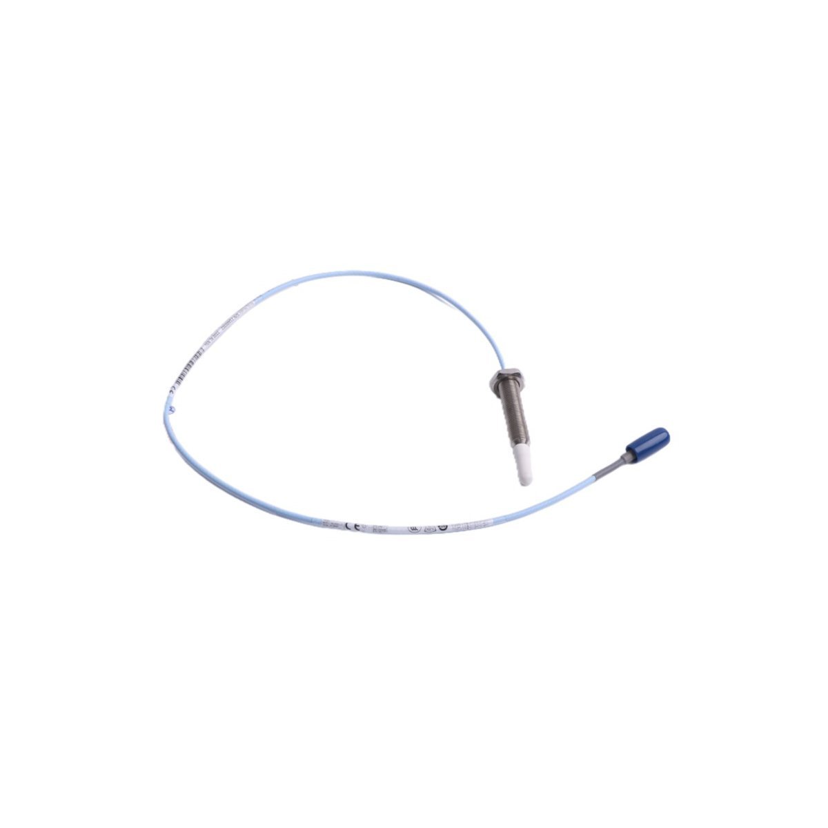
Connect the extension cables from the non-contacting eddy-current probes to the appropriate rear termination terminals.
Maintain a continuous shield drain wire connection from the field junction box to the rack common ground point to prevent industrial electromagnetic interference from corrupting the high-frequency RF signals.
Verify sensor gap settings using a digital voltmeter across the terminal test points prior to commissioning the monitoring loop.
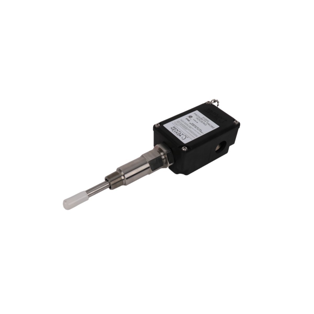
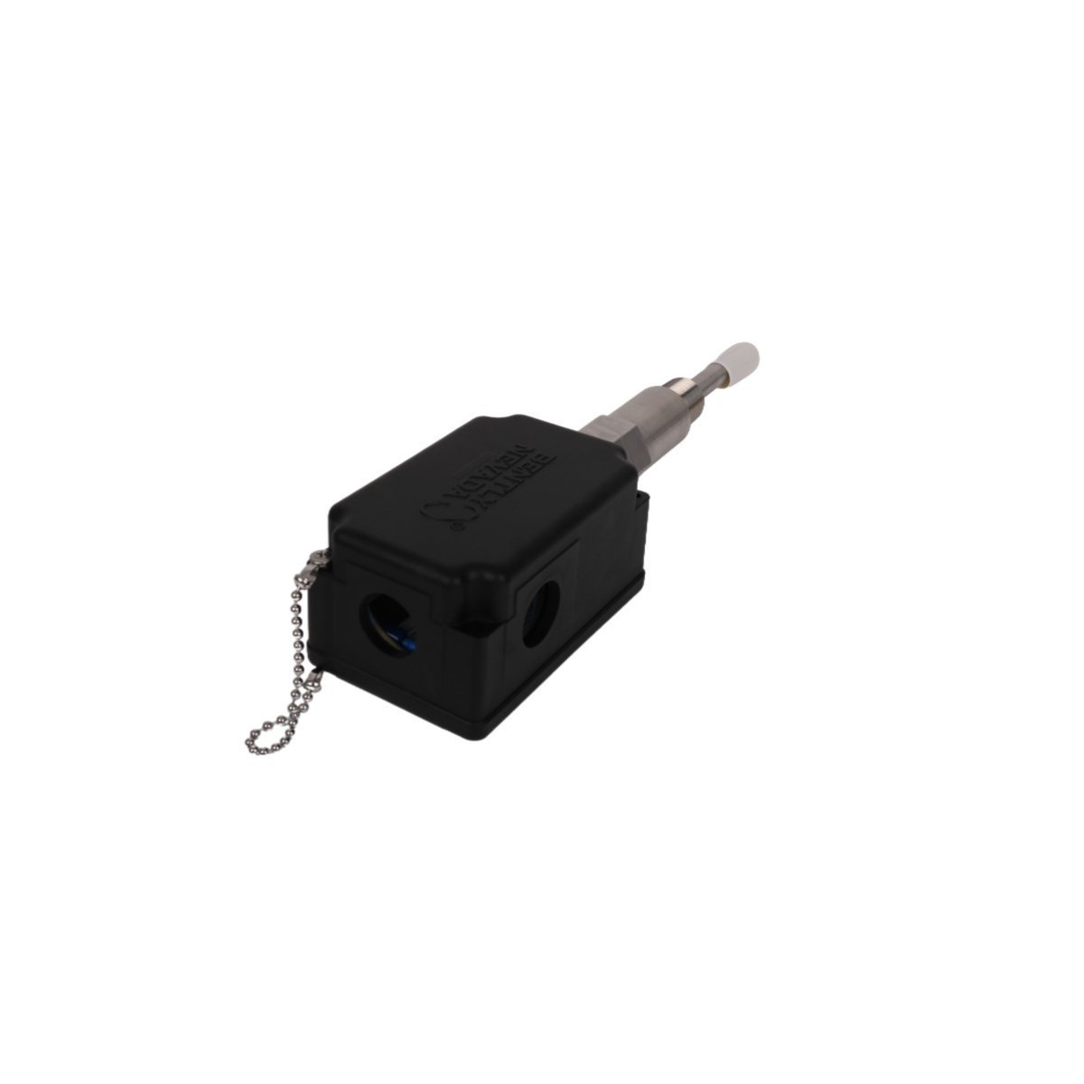
The 31000-16-10-00-050-03-02 Bently Nevada Proximity Probe Housing Assembly is supplied in Brand New condition with Original Stock verification and Global Shipping. Lock in reliable TSI transducer protection now.
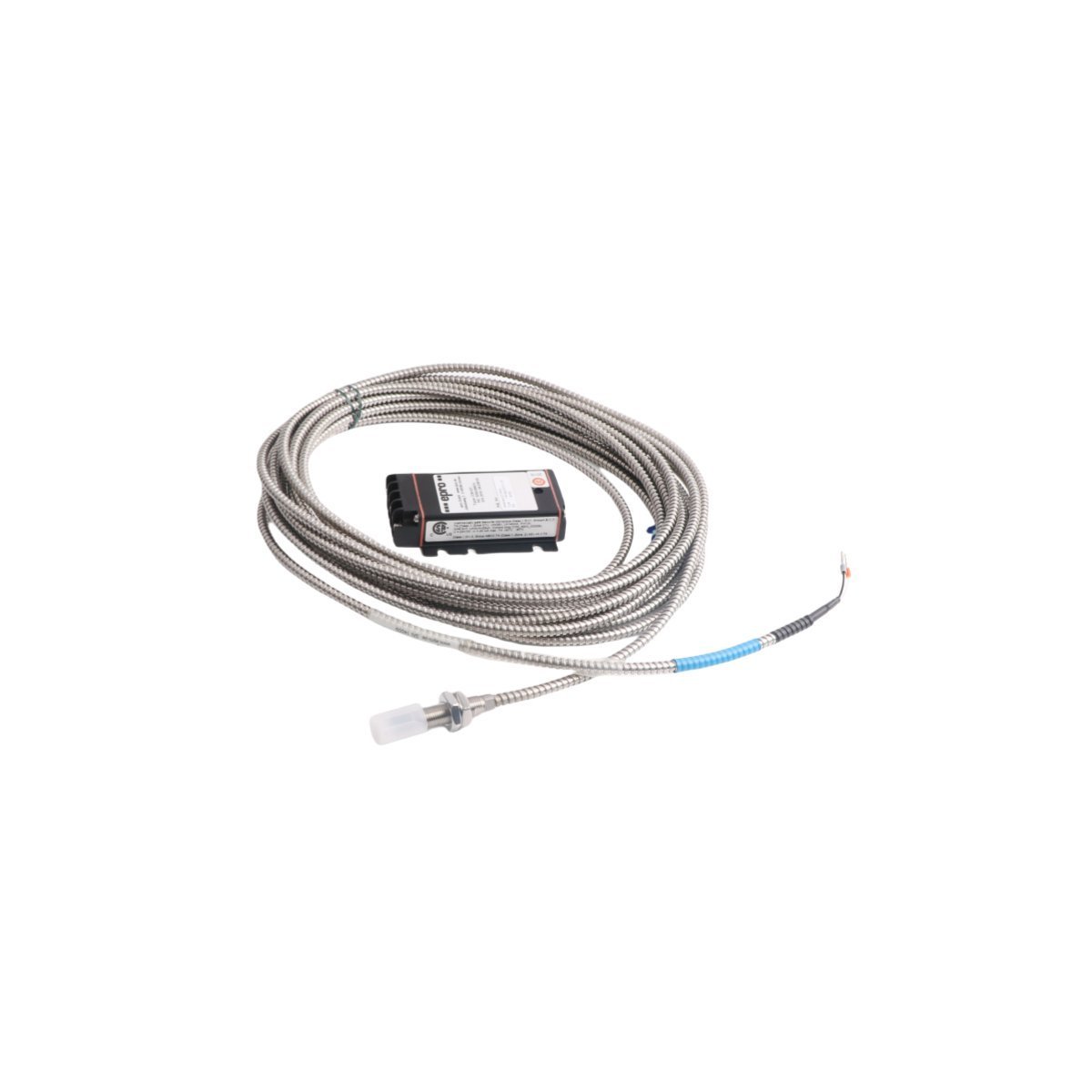
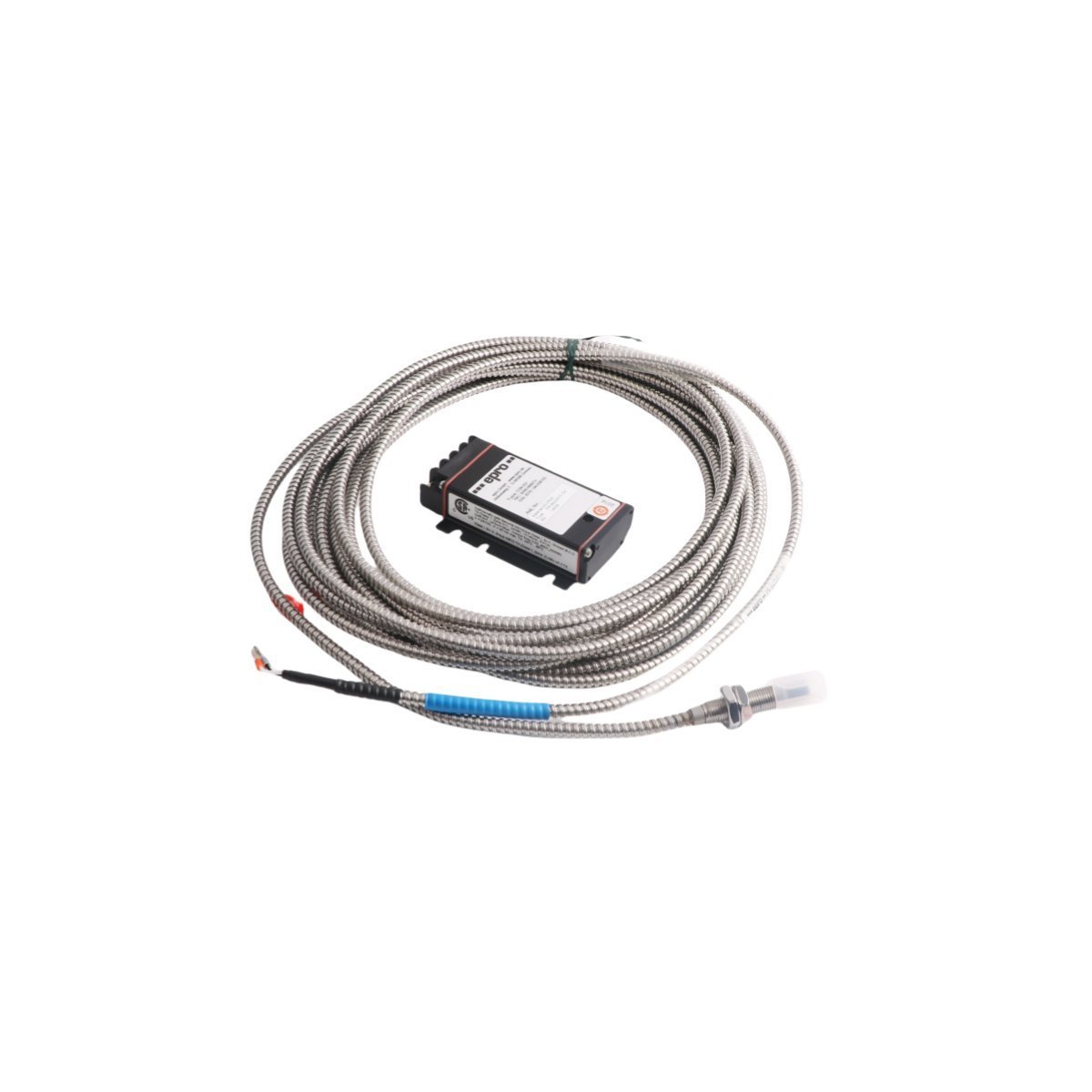
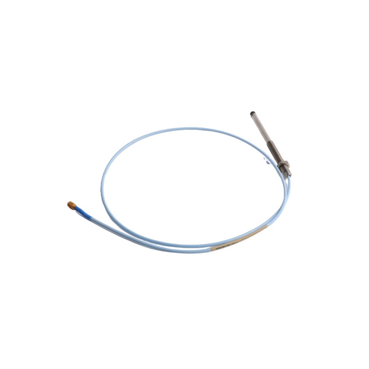
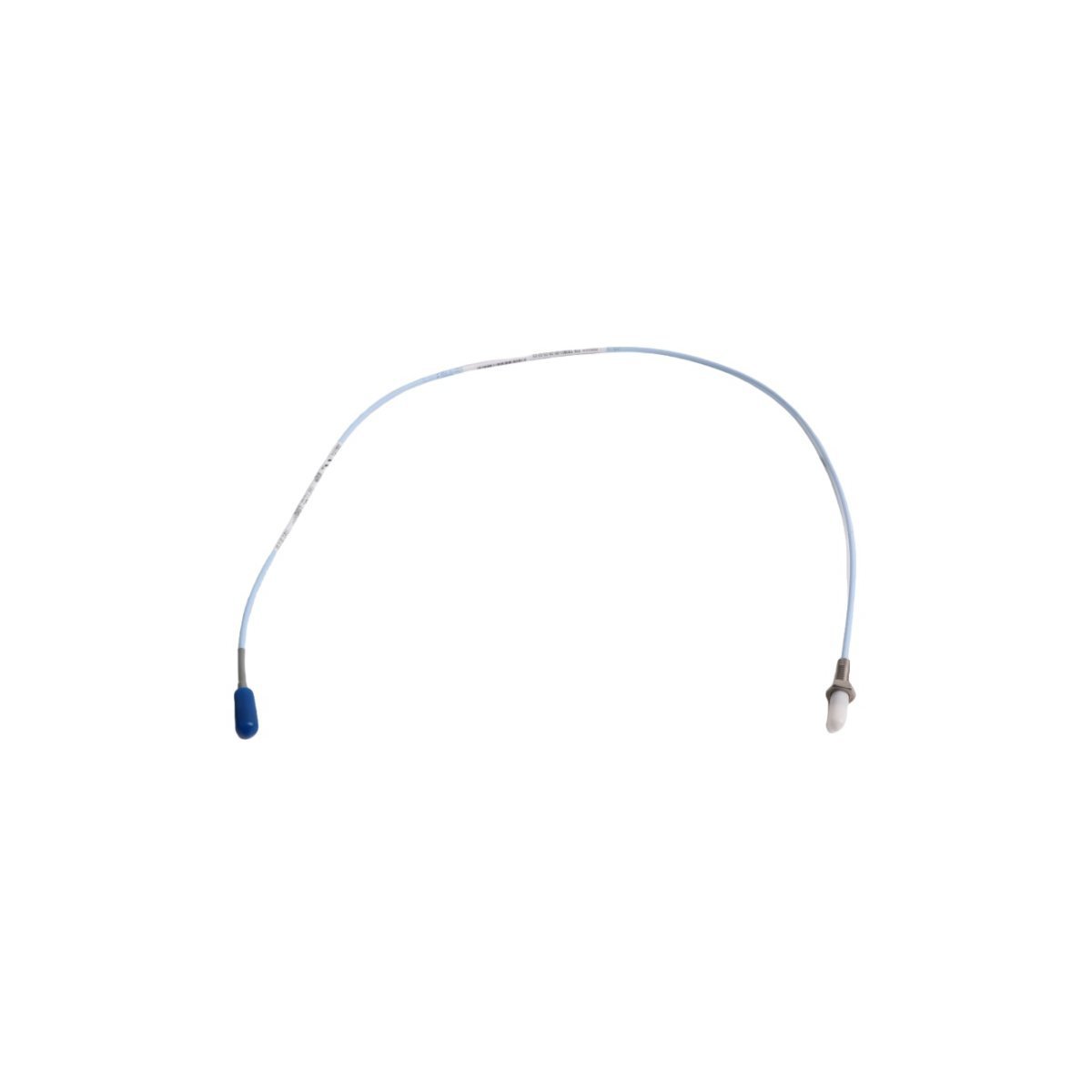
The EMERSON PR6423/011-131 is a high-precision 8mm non-contact eddy current proximity sensor for machinery health monitoring and shaft vibration analysis. Original factory surplus stock is ready to ship globally. Secure your critical turbomachinery asset protection hardware today.
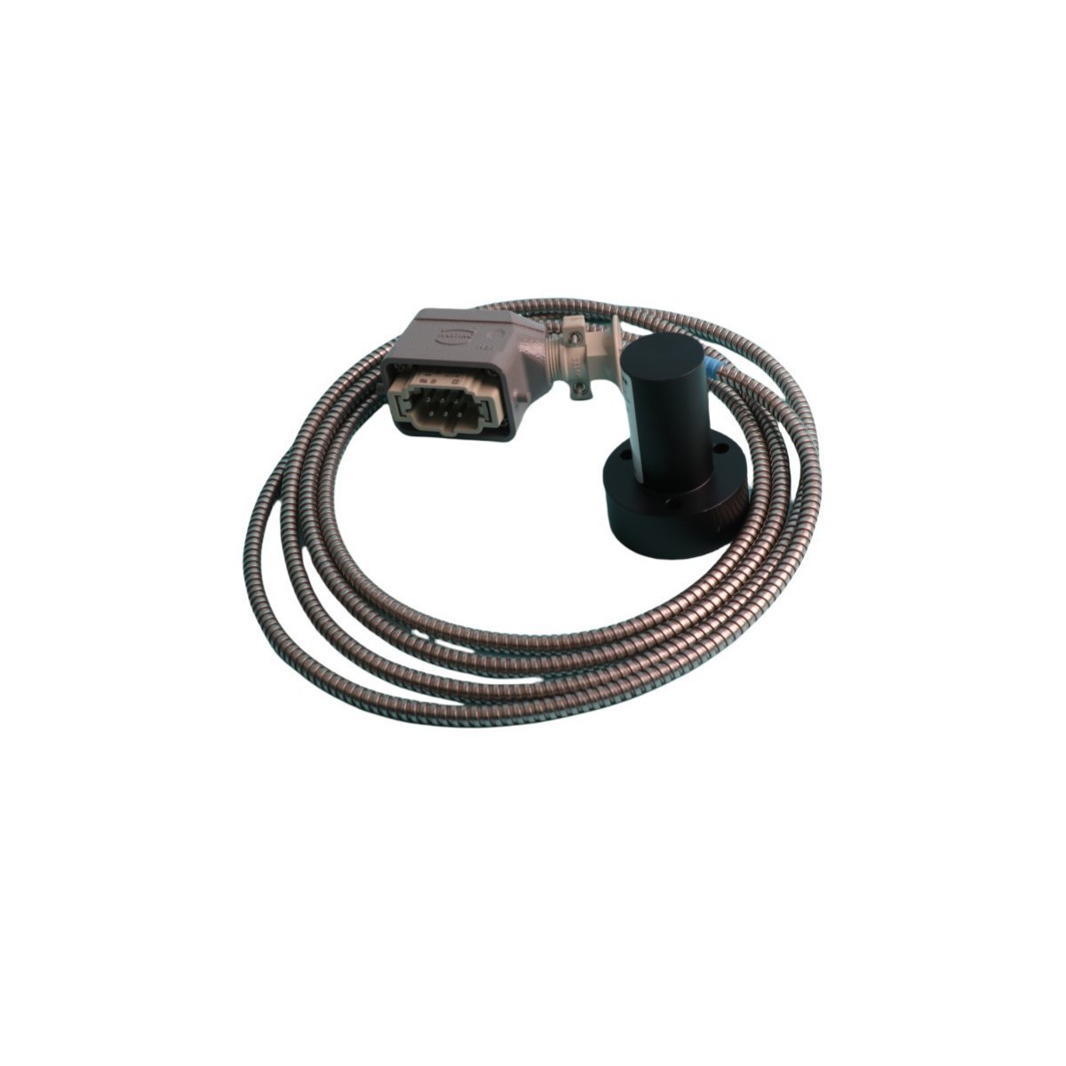
The EMERSON PR9268/017-100 is an electrodynamic seismic velocity sensor. Available as Brand New, Original Stock, with Global Shipping for asset protection.
The Bently Nevada 330103-06-10-10-02-05 is an 8 mm 3300 XL proximity probe featuring an M10 x 1 thread. It includes a 1.0-meter cable and a PPS plastic tip for durable vibration monitoring in hazardous environments.
The Bently Nevada 330905-00-05-05-02-05 is a 3300 NSv proximity probe with M10 x 1 threads and a 0.5-meter cable. It provides high-precision vibration sensing for small-bore machinery.
The Bently Nevada 330903-00-03-10-02-05 is a 3300 XL NSv proximity probe featuring M8x1 threads and a 1.0m cable. It provides high-precision vibration sensing for compact industrial applications.
The Bently Nevada 330901-00-40-05-02-05 is a 3300 NSv proximity probe for high-accuracy vibration monitoring. It requires AISI 4140 steel targets and provides stable displacement data for machinery protection.
The Bently Nevada 330902-05-30-10-02-05 is an armored 3300 NSv proximity probe designed for tight spaces and small targets. It provides accurate vibration and position data for centrifugal compressors.
The Bently Nevada 330104-02-08-10-01-00 is a 3300 XL 8mm proximity probe with M10x1 threads. This 1.0-meter sensor provides precision vibration monitoring for industrial machinery in hazardous areas.
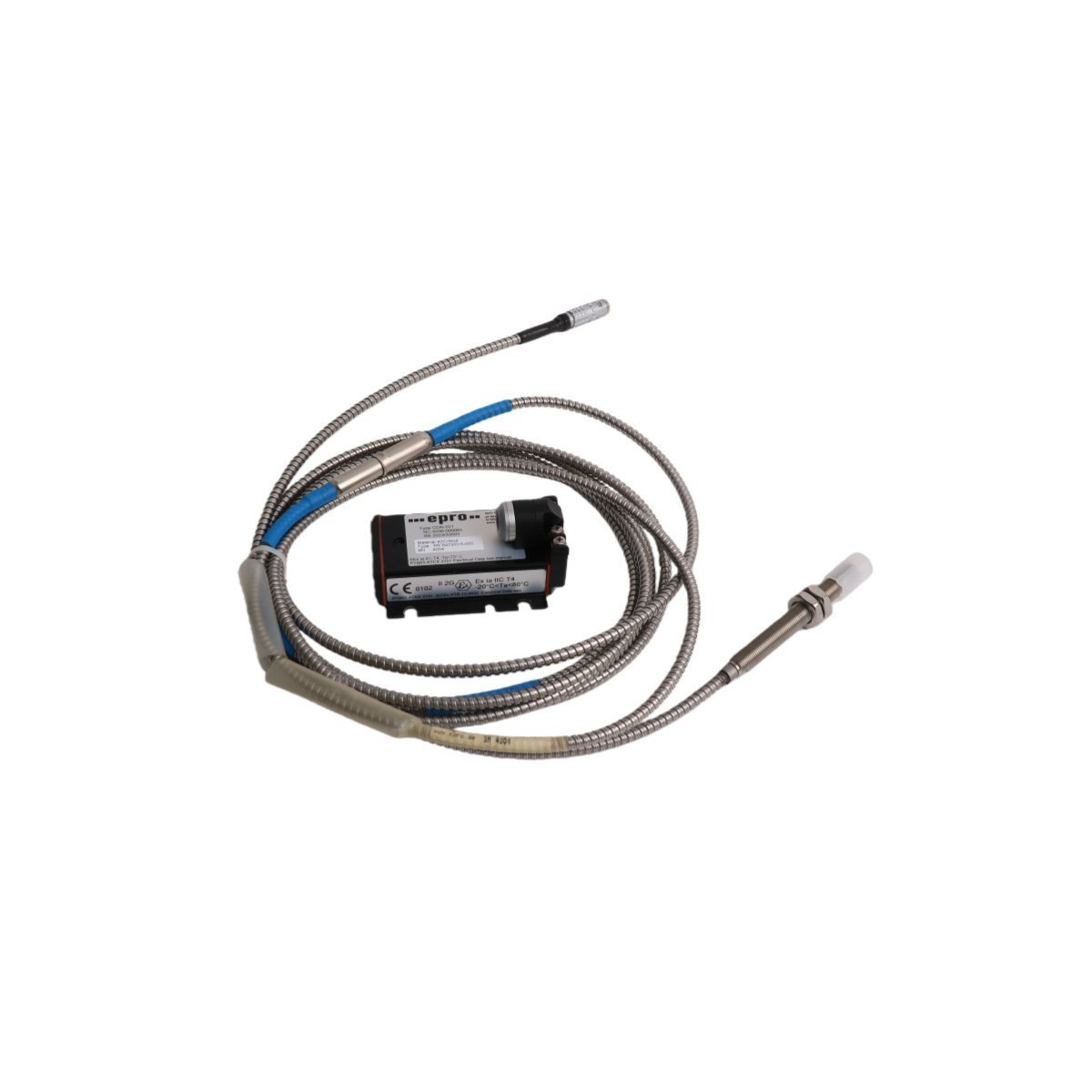
The Emerson EPRO PR6423/10R-141 CON031 is a professional 8mm non-contact eddy current sensor designed for industrial vibration and displacement monitoring. It offers high-precision measurement for rotating machinery, ensuring operational safety and enabling predictive maintenance in harsh environments.
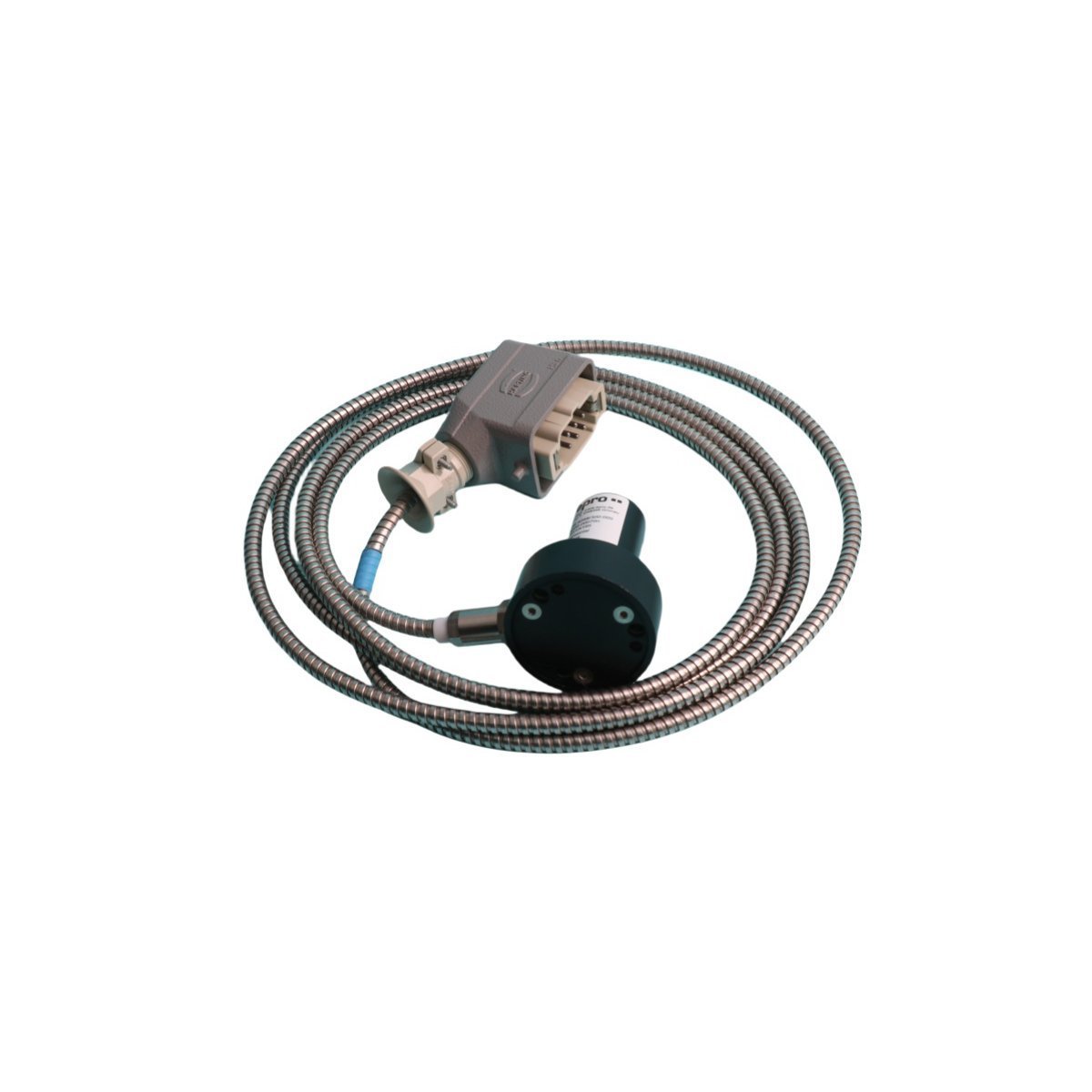
The Emerson PR6423/101-101 (CON031) is an 8mm non-contacting displacement sensor designed for shaft vibration and position monitoring. Featuring an armored 1m cable and ceramic tip, it provides high-precision eddy current measurements for critical rotating machinery.
We are committed to protecting your privacy. The information collected here is strictly used to provide the requested quotes, technical support, and relevant industrial automation solutions.