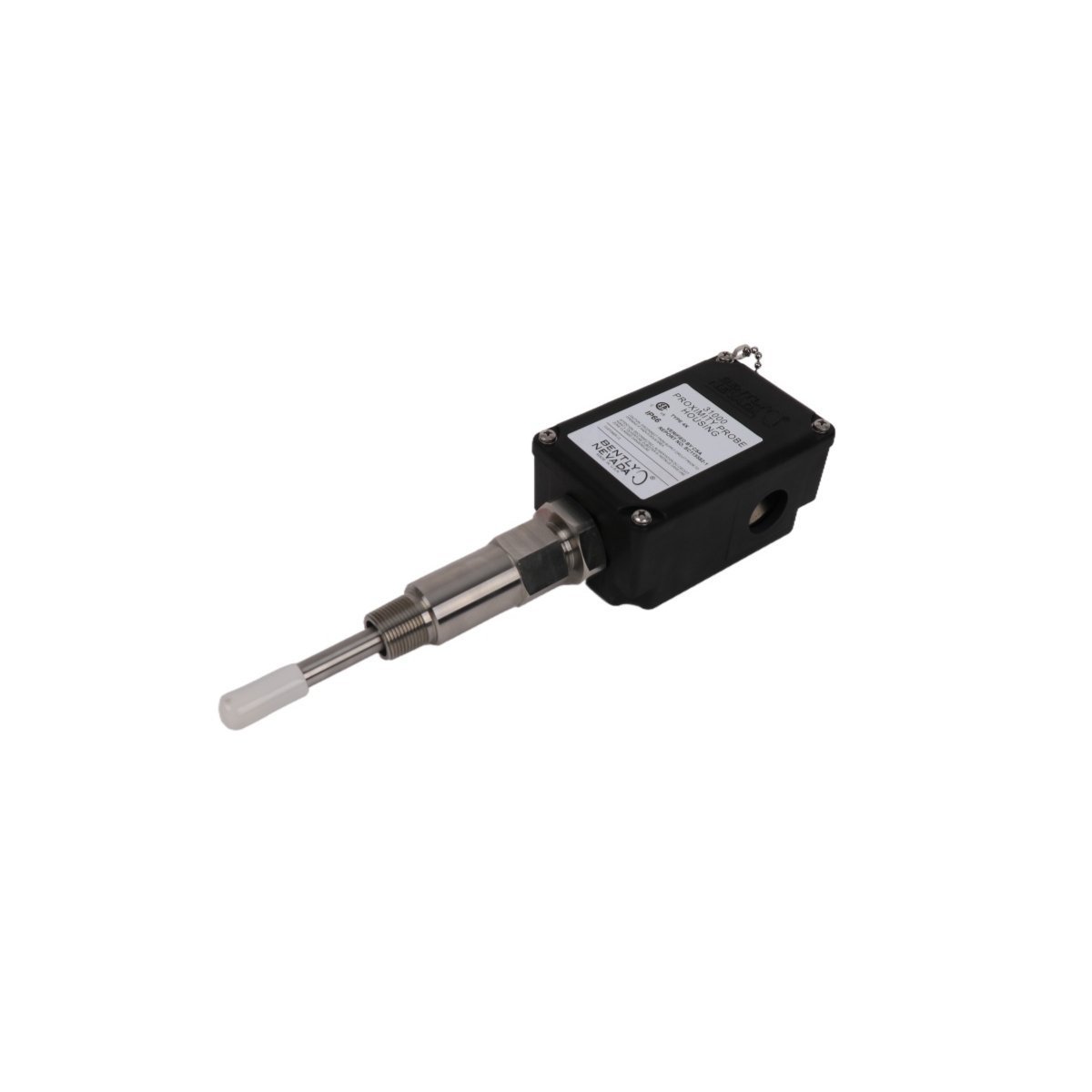
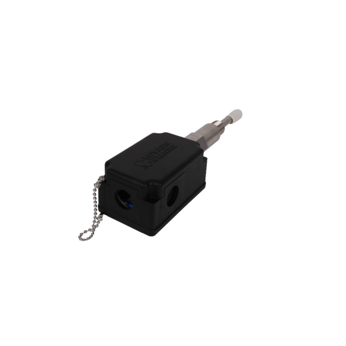
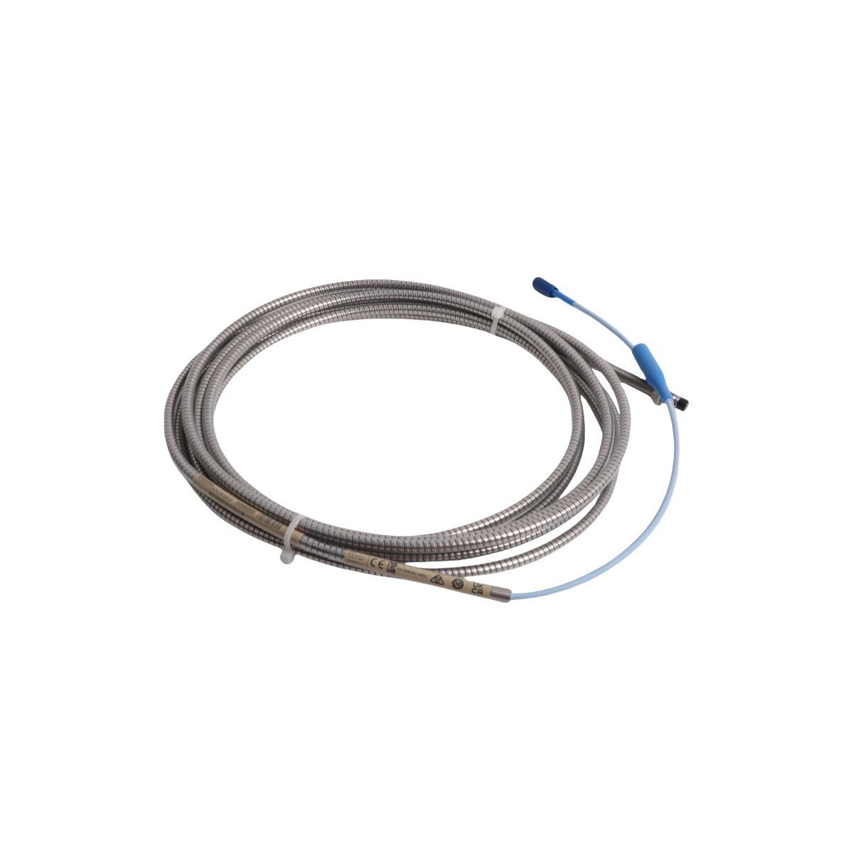
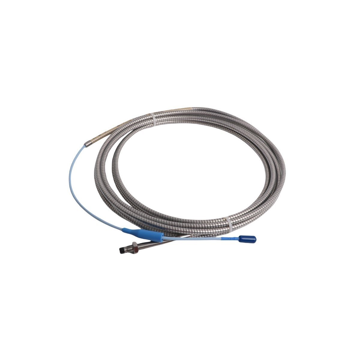
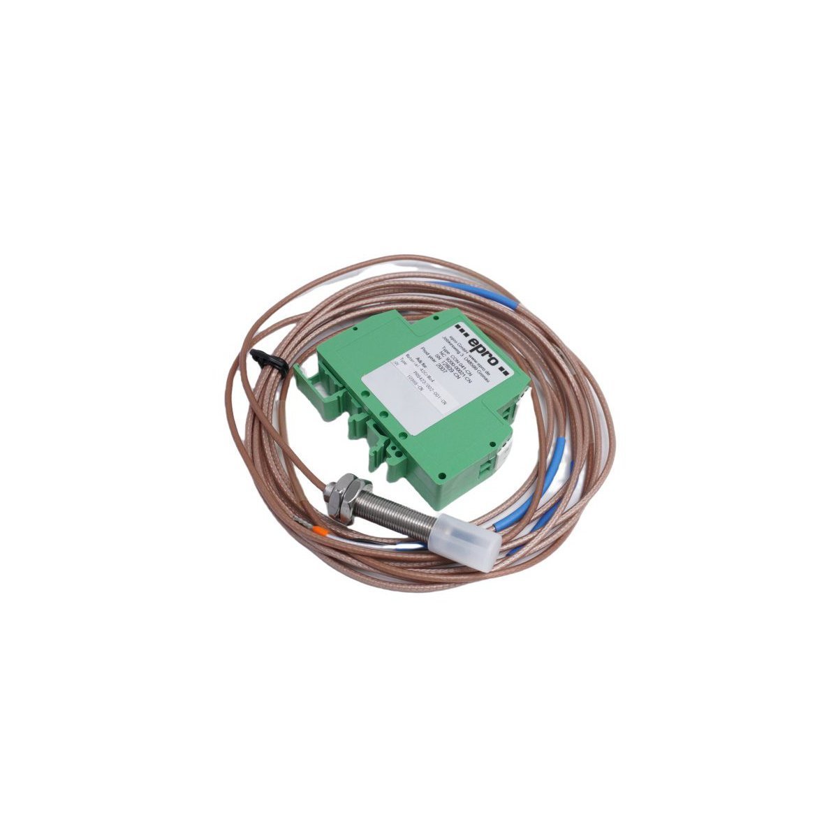
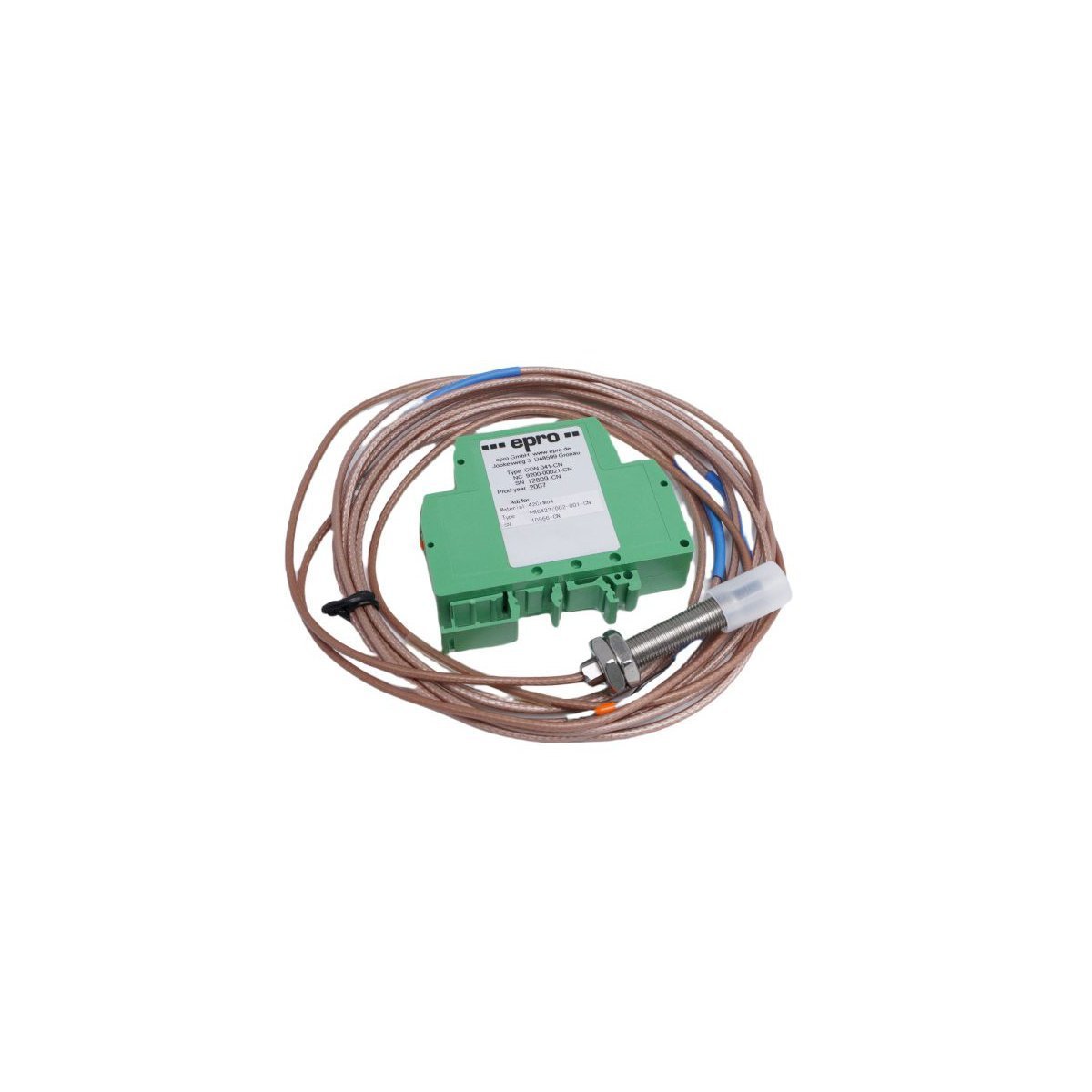
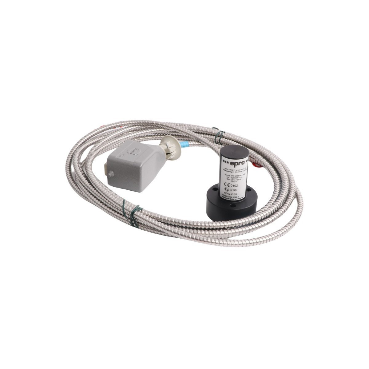
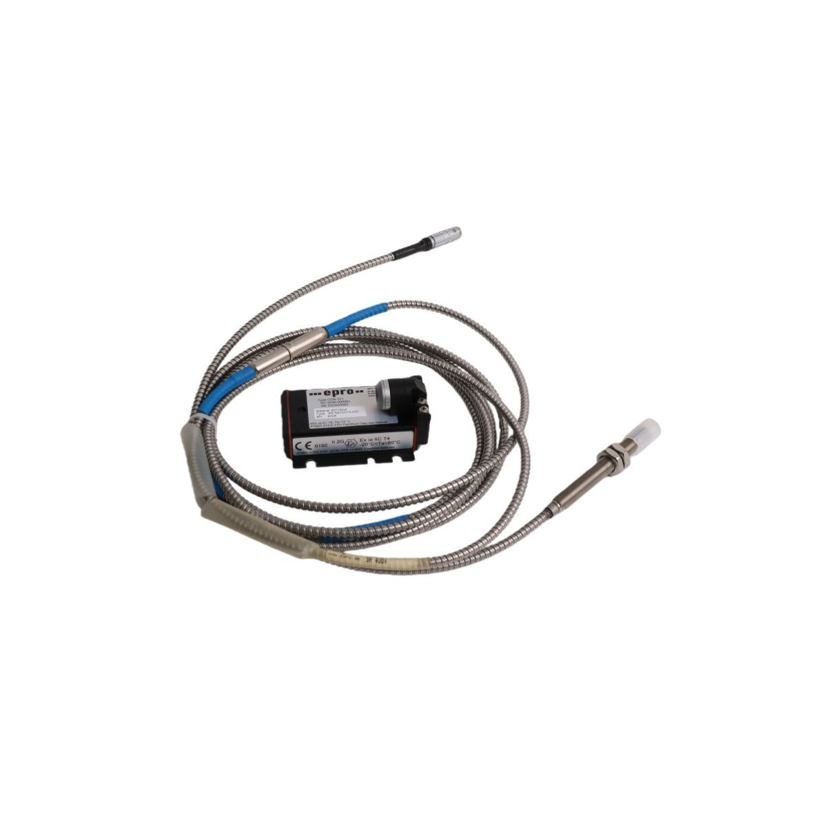
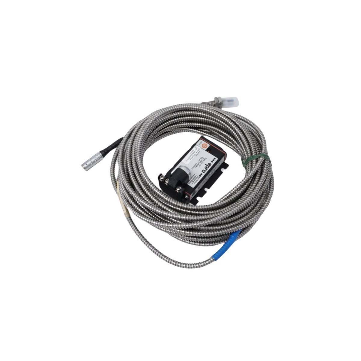
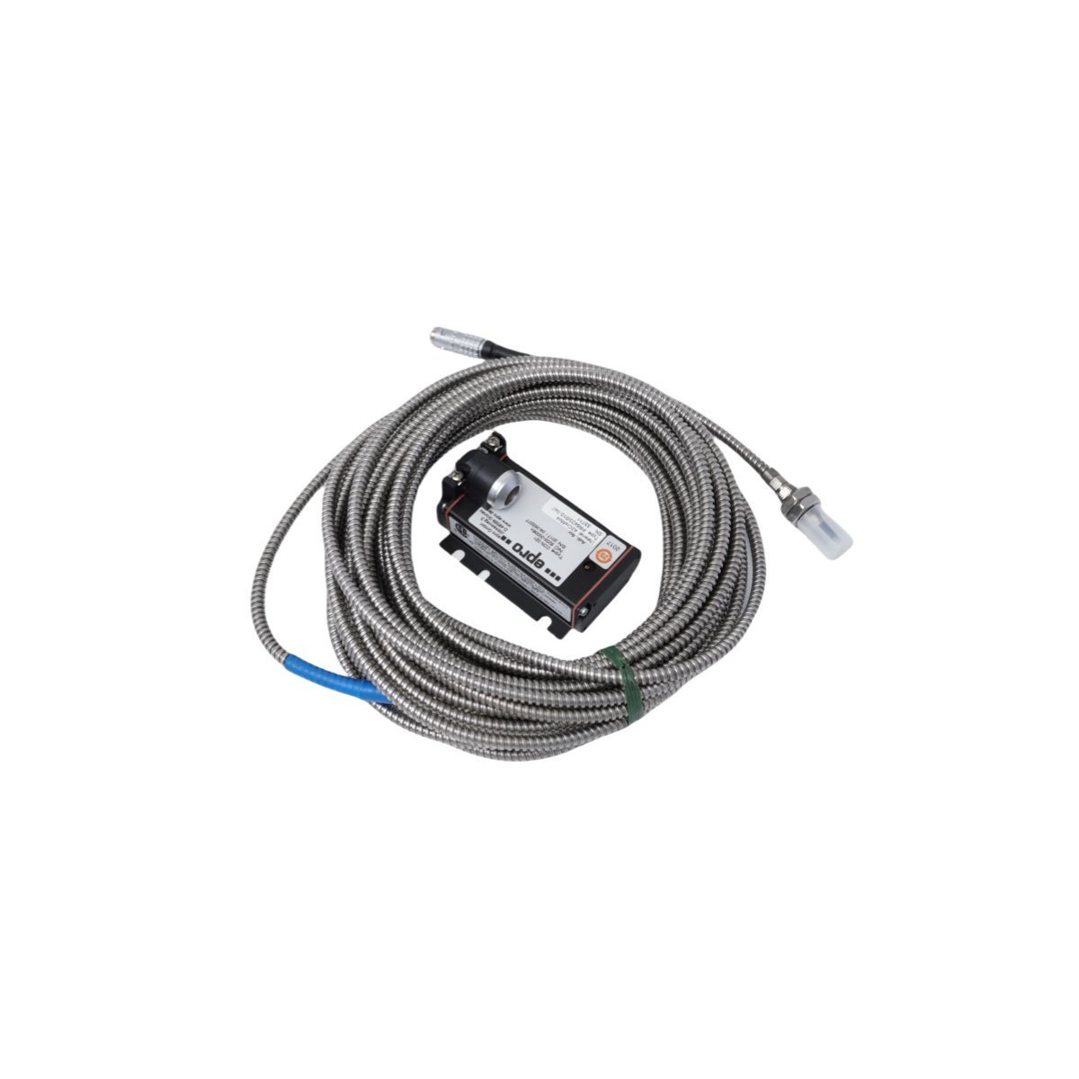
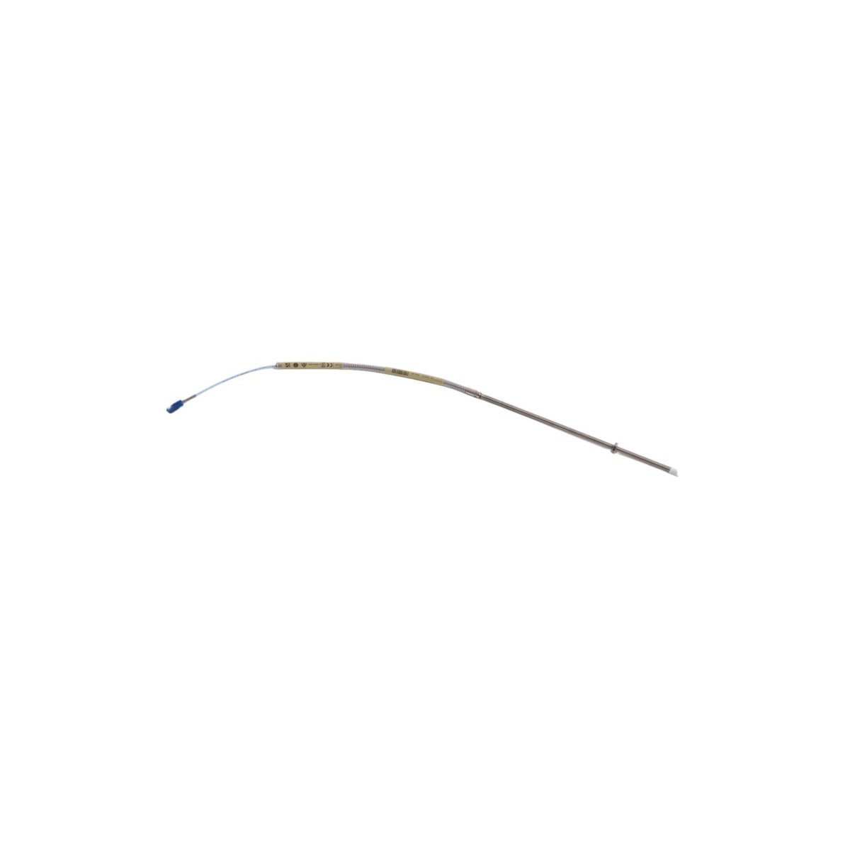
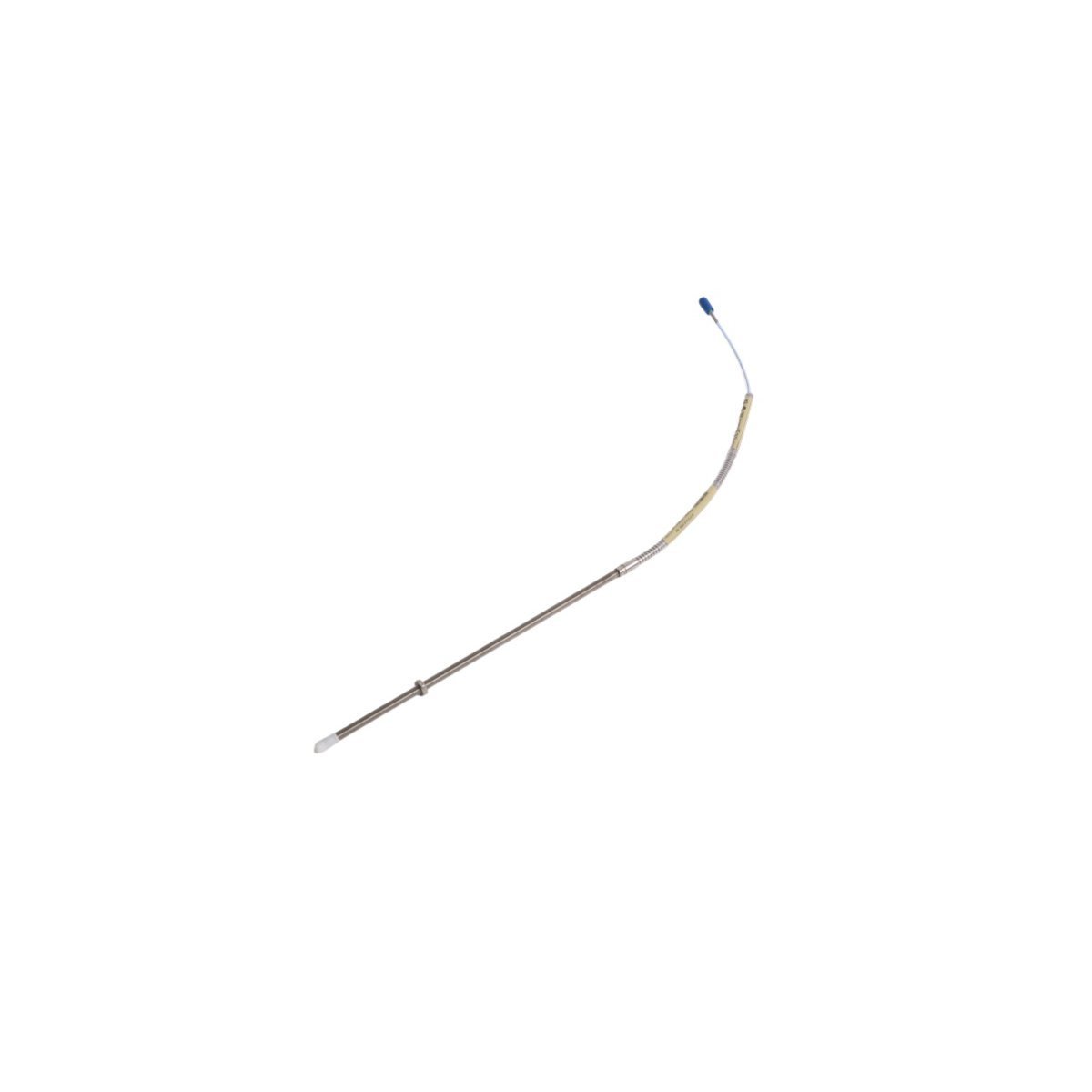
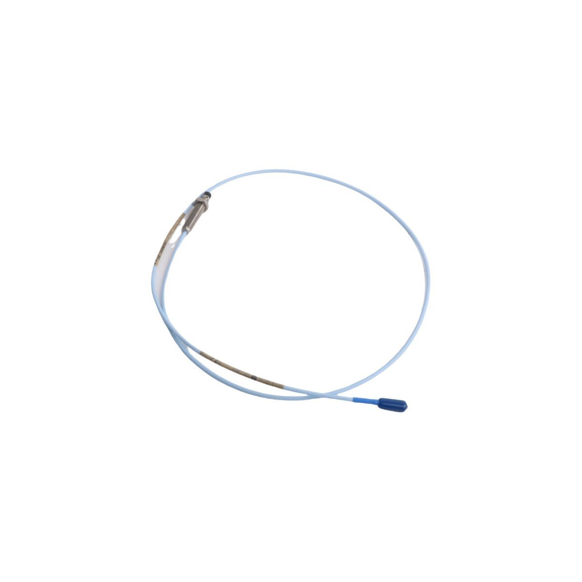
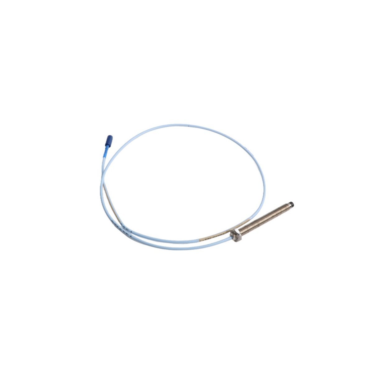
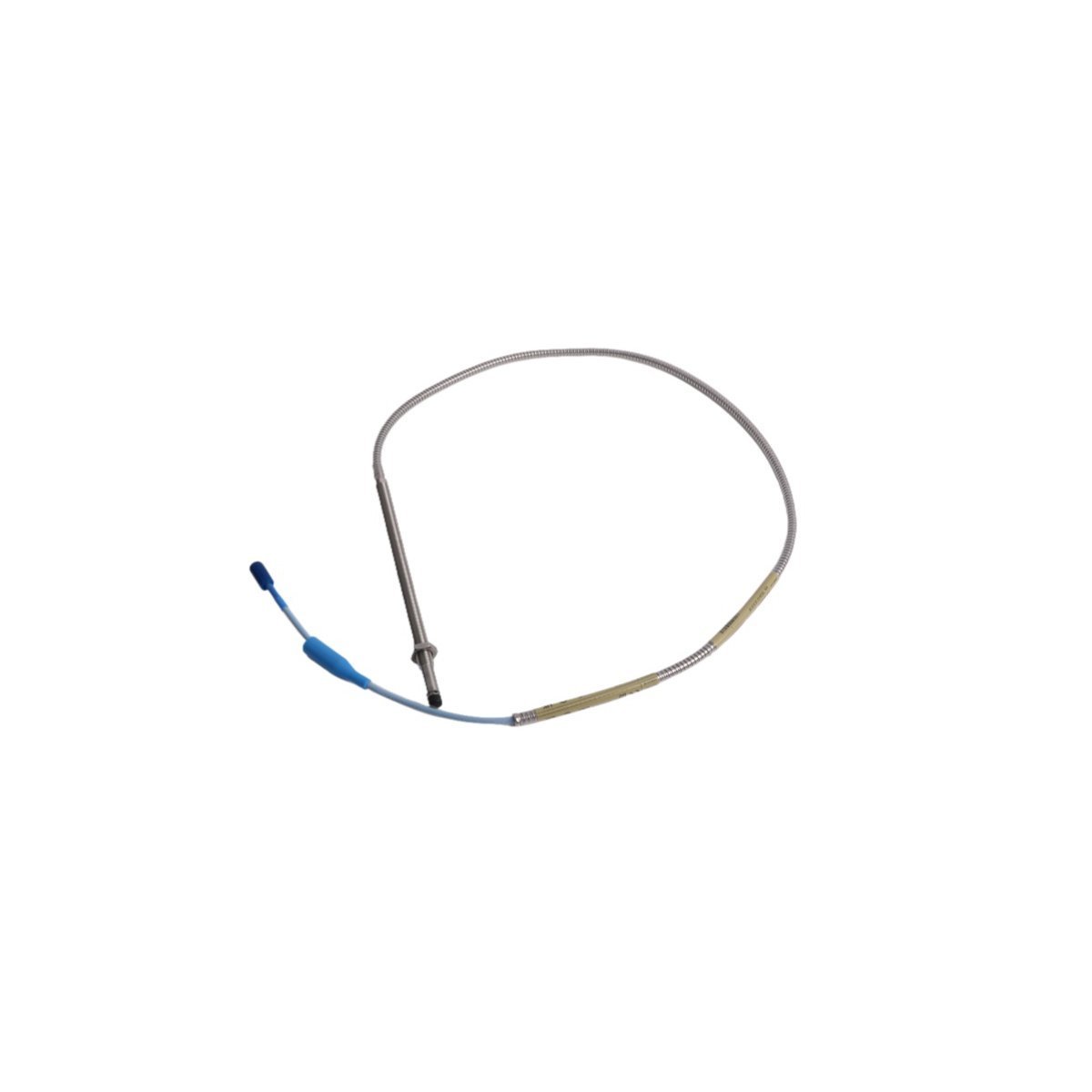
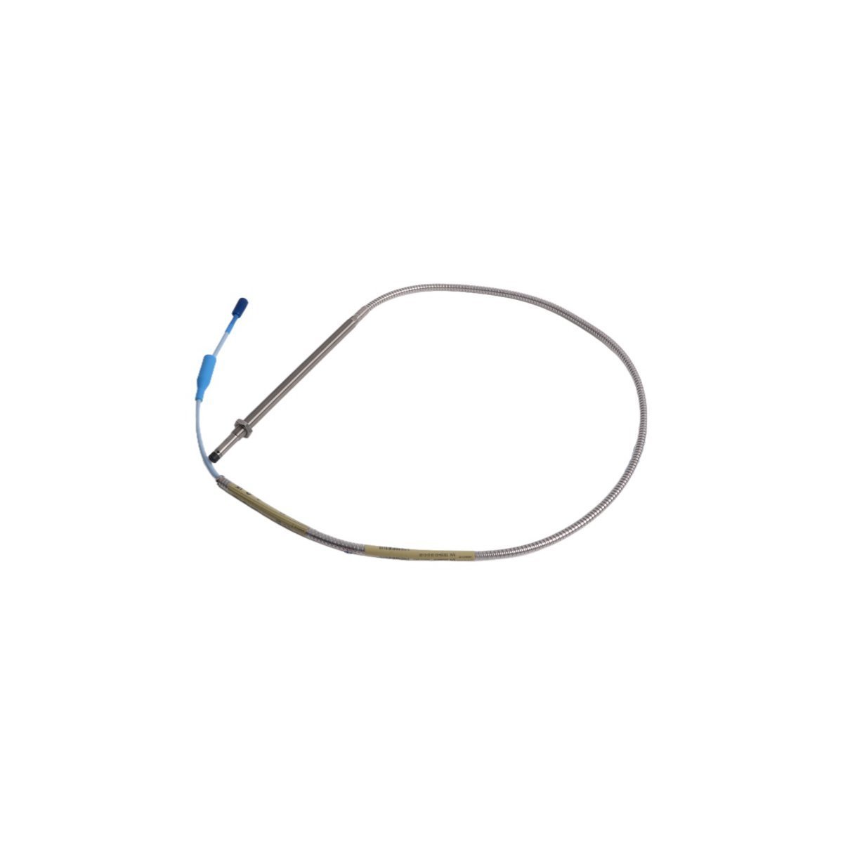
You are here:
SKU: PR9268/017-100

EMERSON PR9268/017-100 EPRO Mechanical Velocity Sensor

The EMERSON PR9268/017-100 is an electrodynamic seismic velocity sensor. Available as Brand New, Original Stock, with Global Shipping for asset protection.

Configured for precise absolute vibration measurement in turbomachinery components, the EMERSON PR9268/017-100 (PR9268 Mechanical velocity sensor) provides direct physical/electrical execution. The instrument operates via an electrodynamic seismic mass coil measuring structural velocity down to 4 Hz across critical rotating asset bearing housings.

Hardware Specifications

ParameterSpecification
ModelPR9268/017-100
BrandEMERSON
OriginUSA
Weight0.74 kg
Dimensions23.0 x 22.0 x 3.0 cm
Operating Temp-20 to +100 deg C
Power ConsumptionLoop-powered, 4-20 mA interface
Frequency Response4 Hz to 10 kHz
Measurement AxisSingle axis, vertical or horizontal depending on alignment
Enclosure RatingIP67
Housing MaterialStainless steel

4-20 mA HART Loop Protocol and Channel-to-Channel Isolation

The PR9268/017-100 integrates internal transducer electronics designed to convert seismic mass relative displacement directly into a linear 4-20 mA HART loop protocol signal. The loop interface utilizes channel-to-channel isolation parameters within the companion monitoring racks to eliminate systemic ground loops across separate machine housings. The frequency response characteristic is linear within +/- 5% tolerances over the 4 Hz to 10 kHz band. This ensures that sub-synchronous faults and high-frequency structural harmonics are preserved during processing inside the monitoring rack without signal degradation from thermal variations or electromagnetic field interference.

Frequently Asked Questions

Q: What are the primary orientation restrictions for mounting this electrodynamic velocity sensor?

A: Electrodynamic sensors with the /017 suffix are calibrated for specific internal spring suspension orientations. The orientation must match the targeted measurement axis (vertical or horizontal) to prevent internal coil scraping against the permanent magnet assembly.

Q: Is external power configuration needed for raw signal transmission?

A: No. The internal circuitry uses a two-wire loop-powered architecture. The loop derives its operating power directly from the 24 VDC supply provided by the input channels of the machinery protection system or DCS.

Q: How does the IP67 housing handle local atmospheric humidity and chemical exposure?

A: The hermetically sealed stainless steel housing prevents the ingress of moisture, oil mist, and industrial solvents. Interfacing requires matching IP67-rated industrial cables and sealed connector boots to maintain environmental specifications at the connection interface.

Field Installation Guidelines

  • Mounting Plane Rigid Alignment: The mounting surface must be machined flat within 0.05 mm and tapped perpendicular to the asset axis. Ensure the stud engagement achieves a minimum of 5 full threads to prevent high-frequency signal attenuation caused by structural resonance.
  • Shielding and Common Grounding: Route the two-wire twisted pair cable inside a dedicated, grounded flexible conduit. The cable shield must be terminated at a single point inside the instrument rack terminal panel; the sensor side of the shield must remain ungrounded to avoid parasitic loops.
  • Mechanical Stress Relief: Allow a distinct loop radius in the flexible conduit directly adjacent to the sensor body. This minimizes structural tension on the connector pin block caused by continuous machine expansion and thermal cycling.