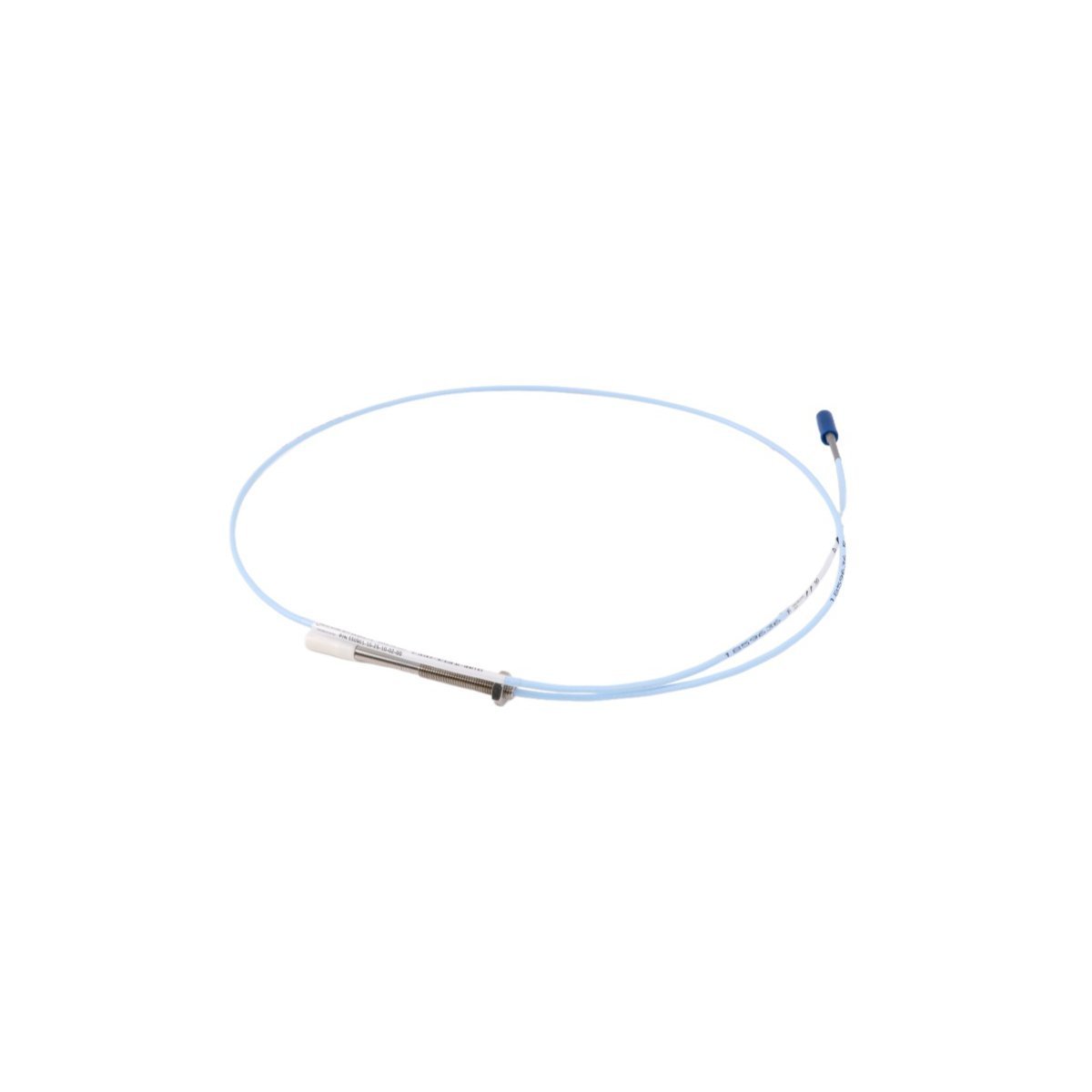
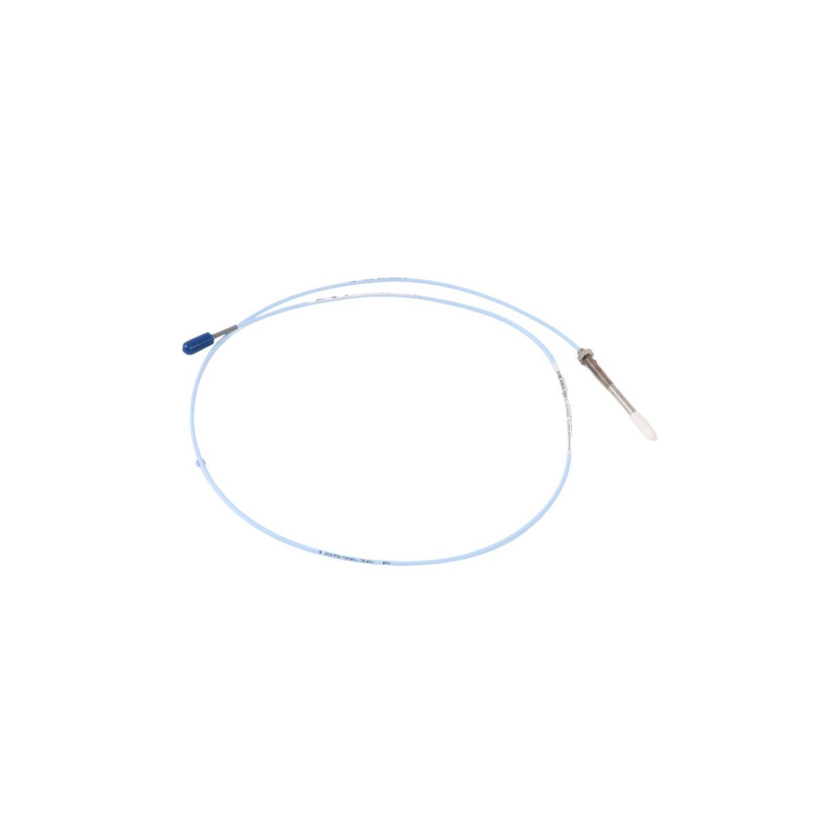
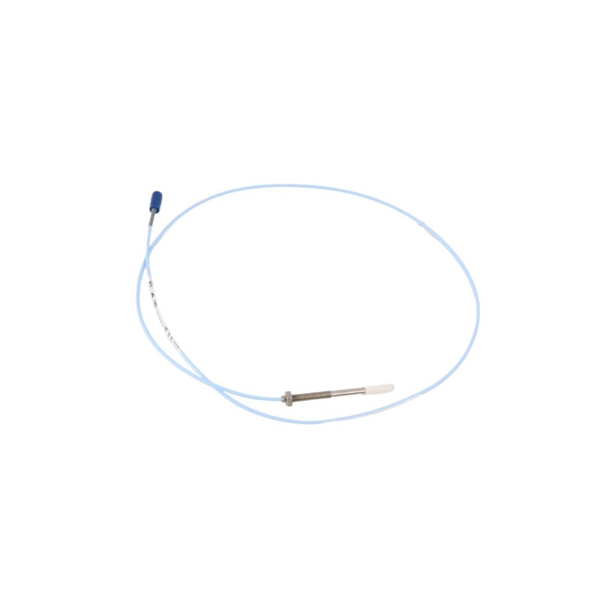
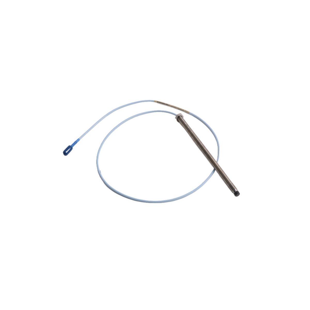
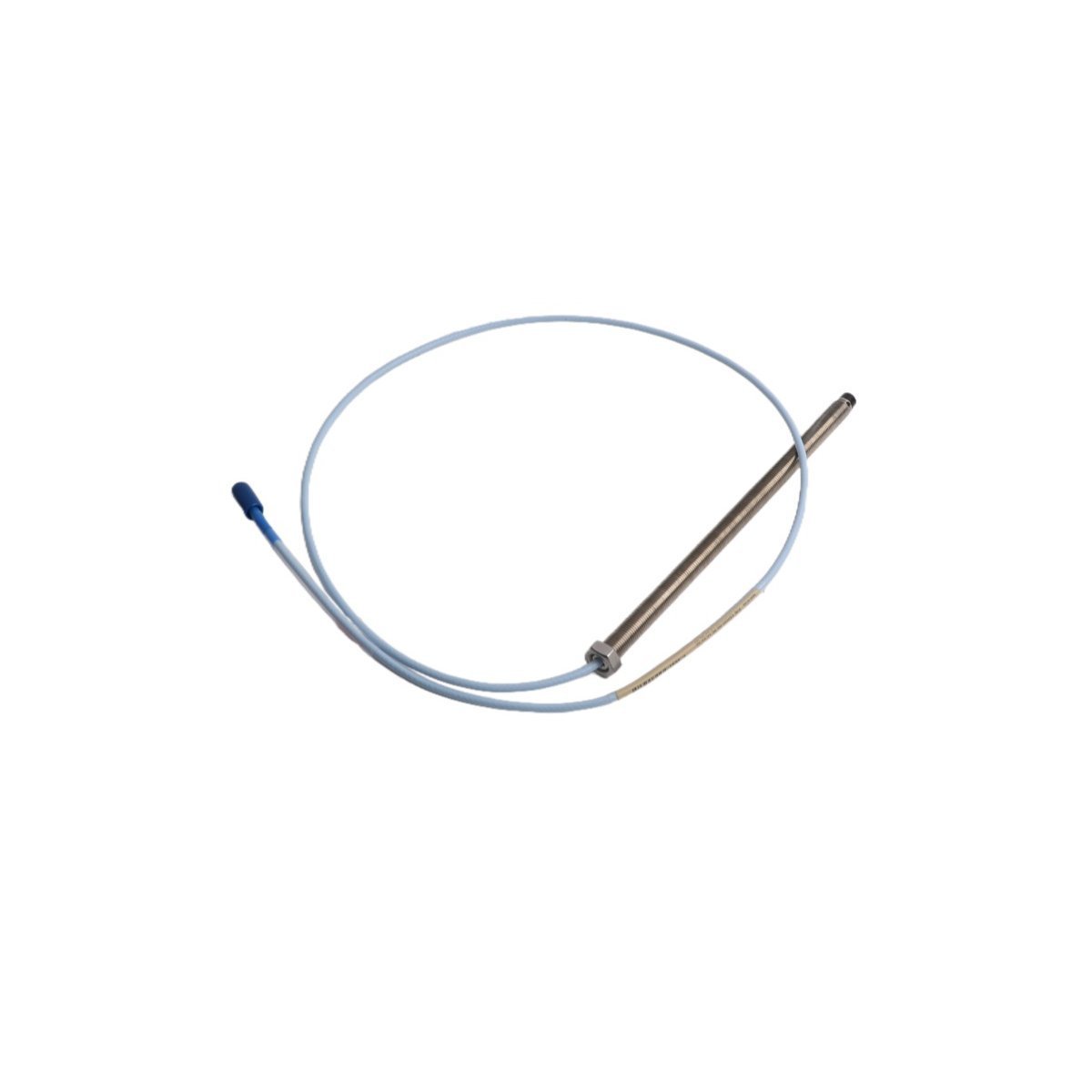
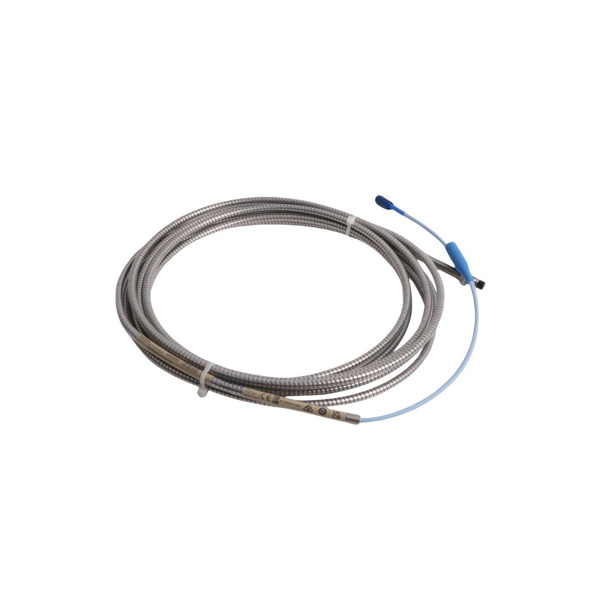
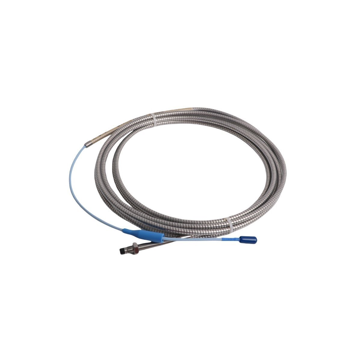
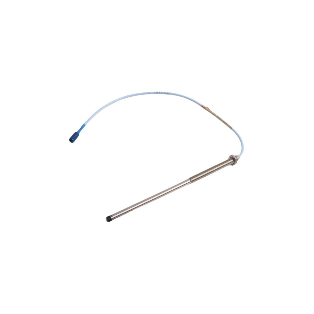
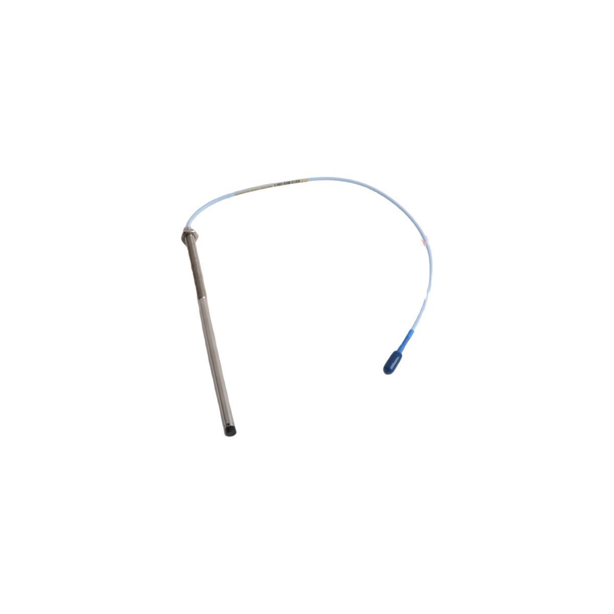
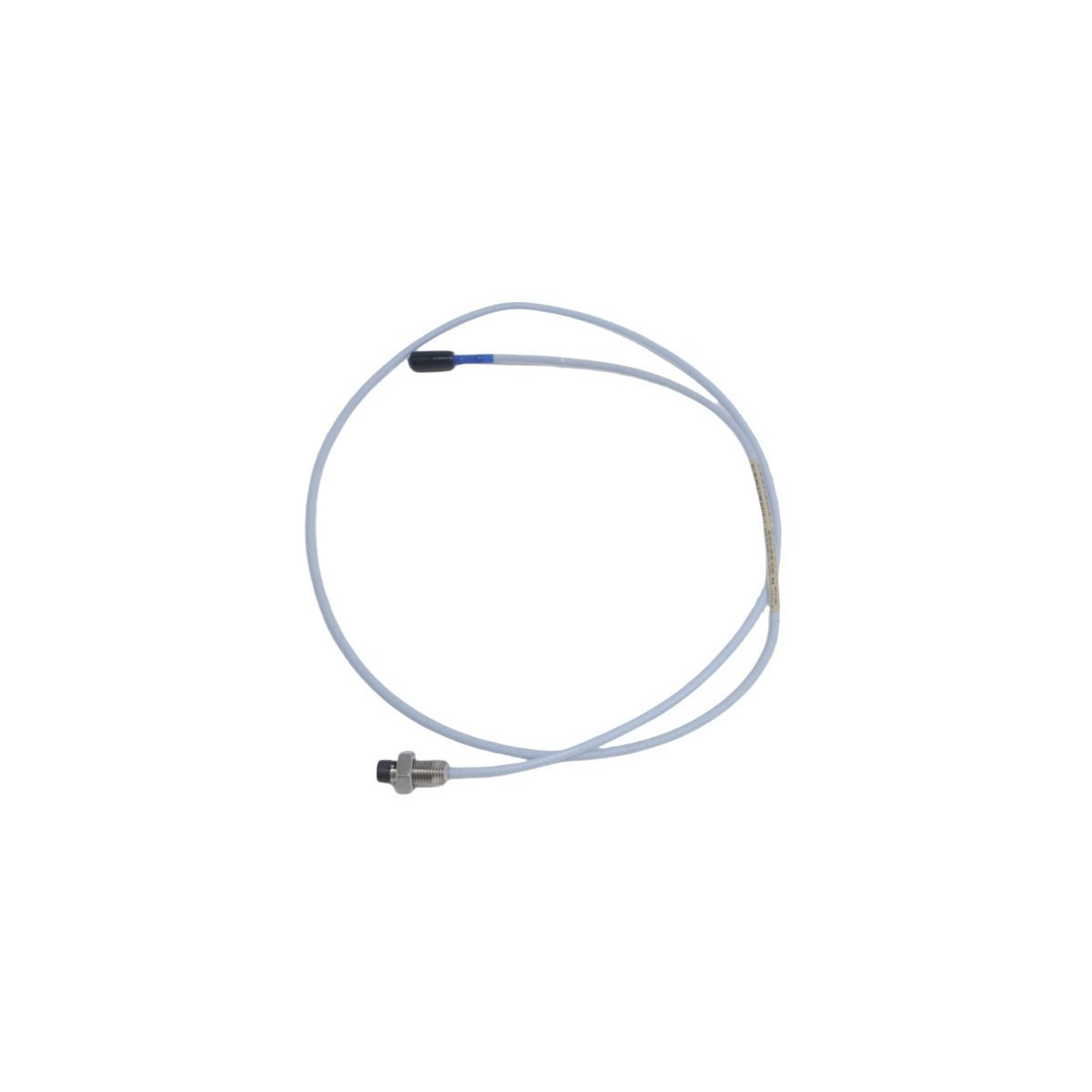
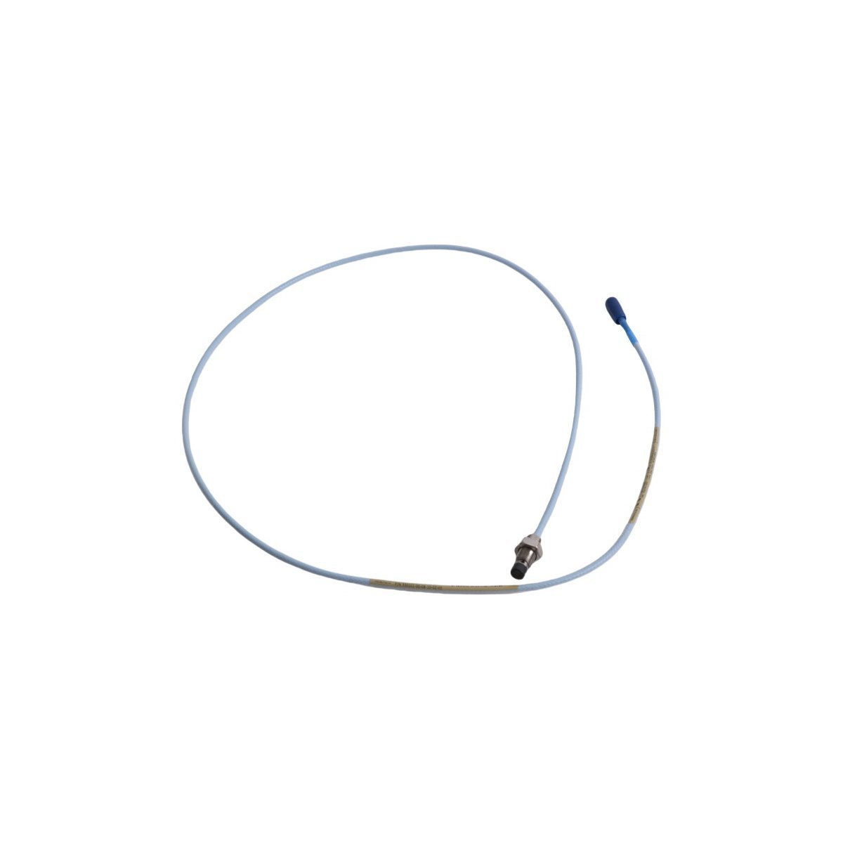
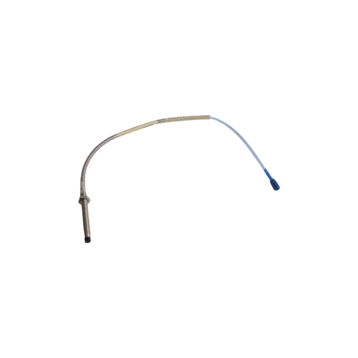
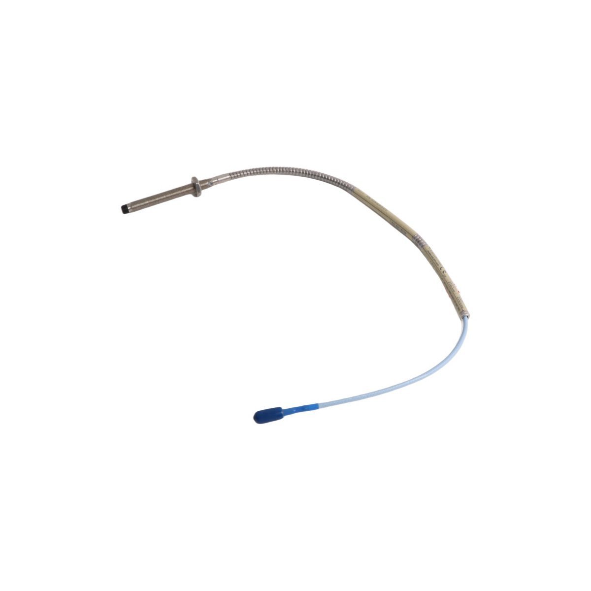
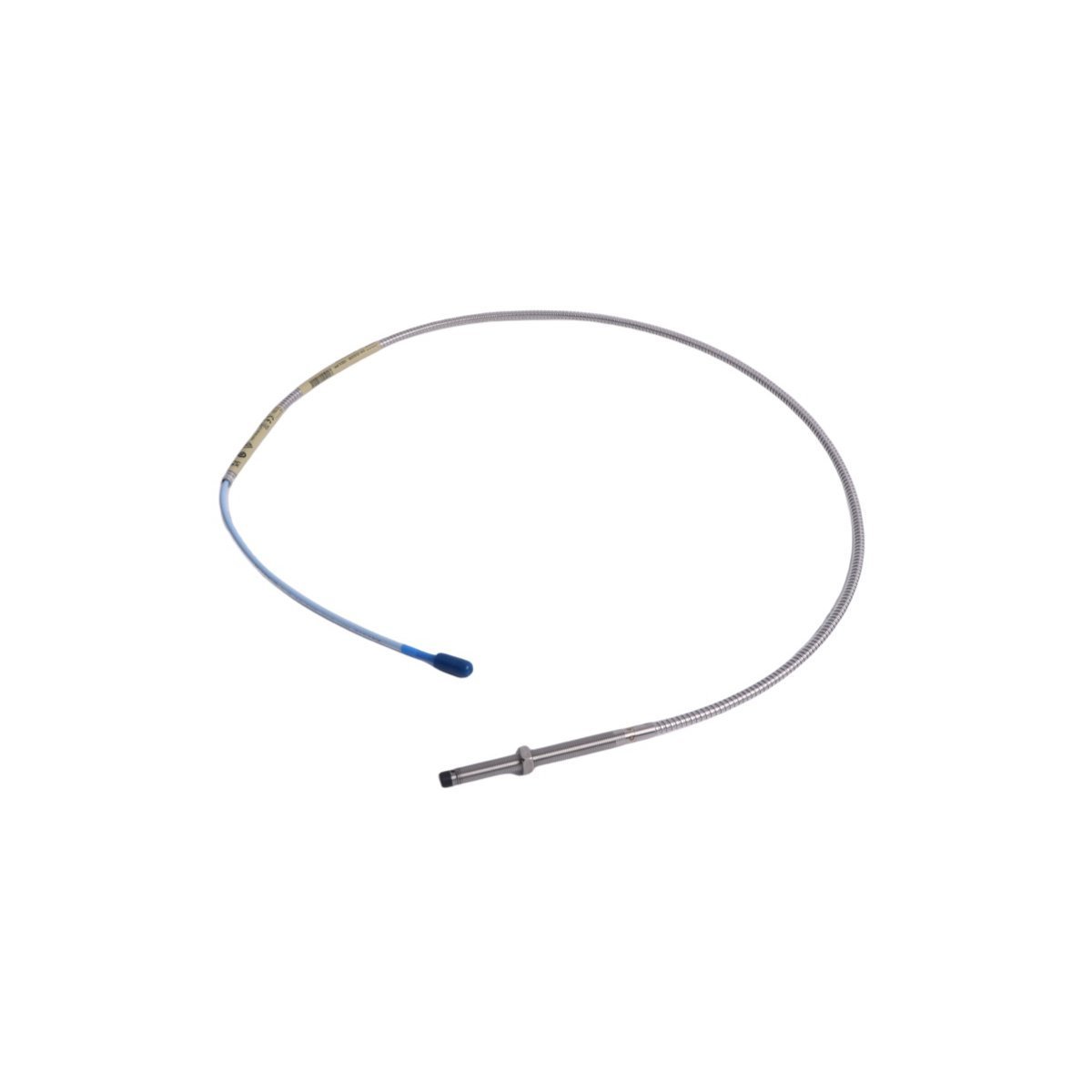
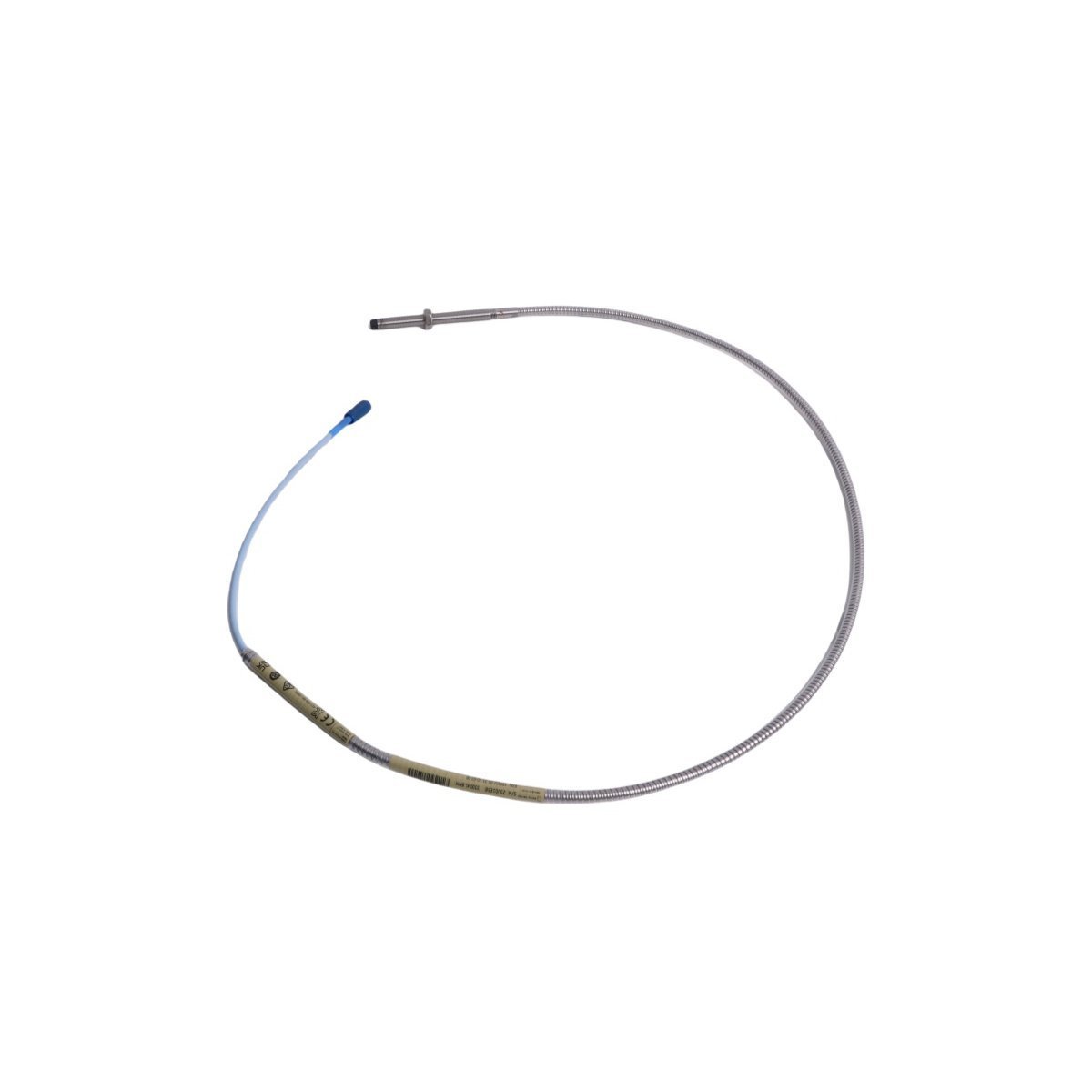
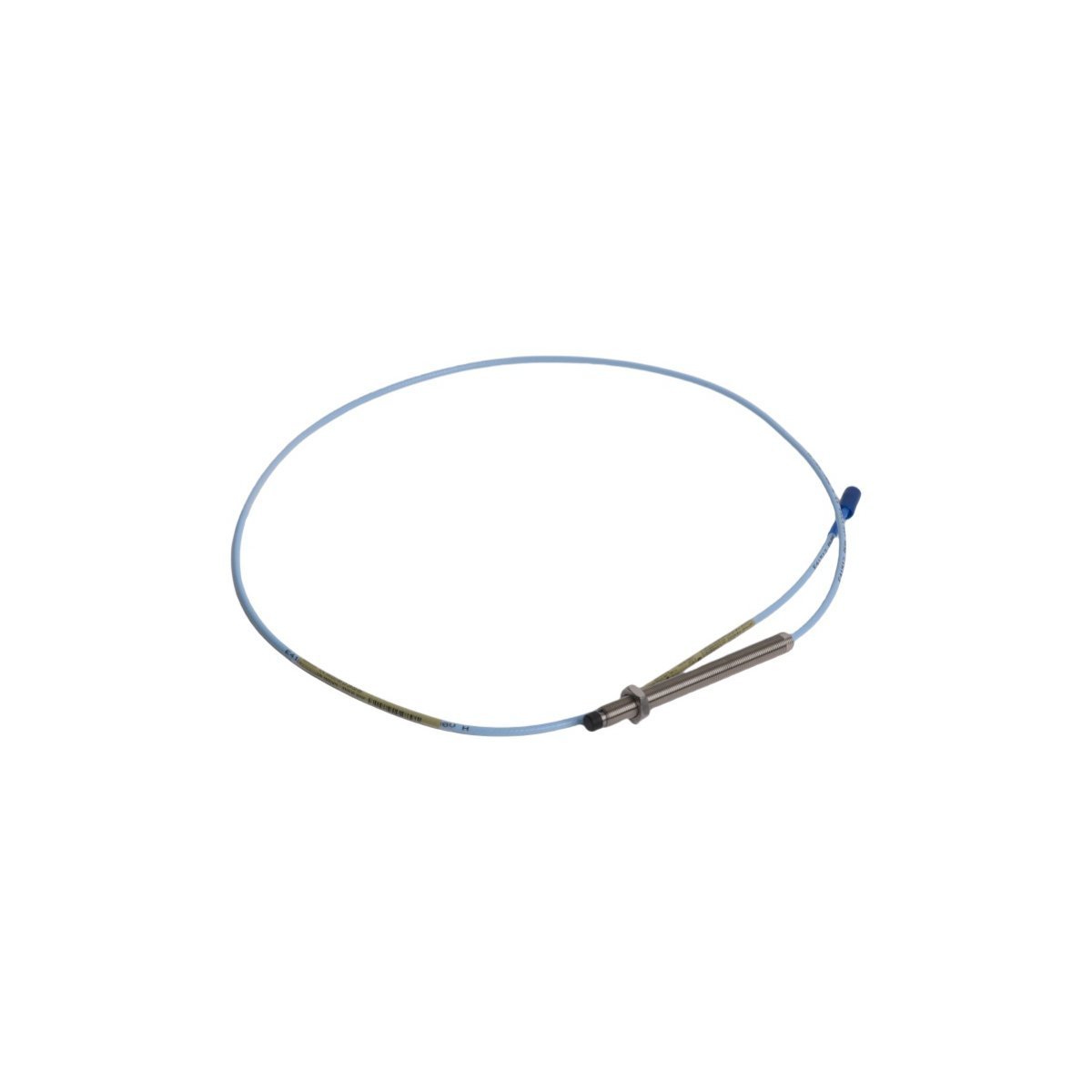
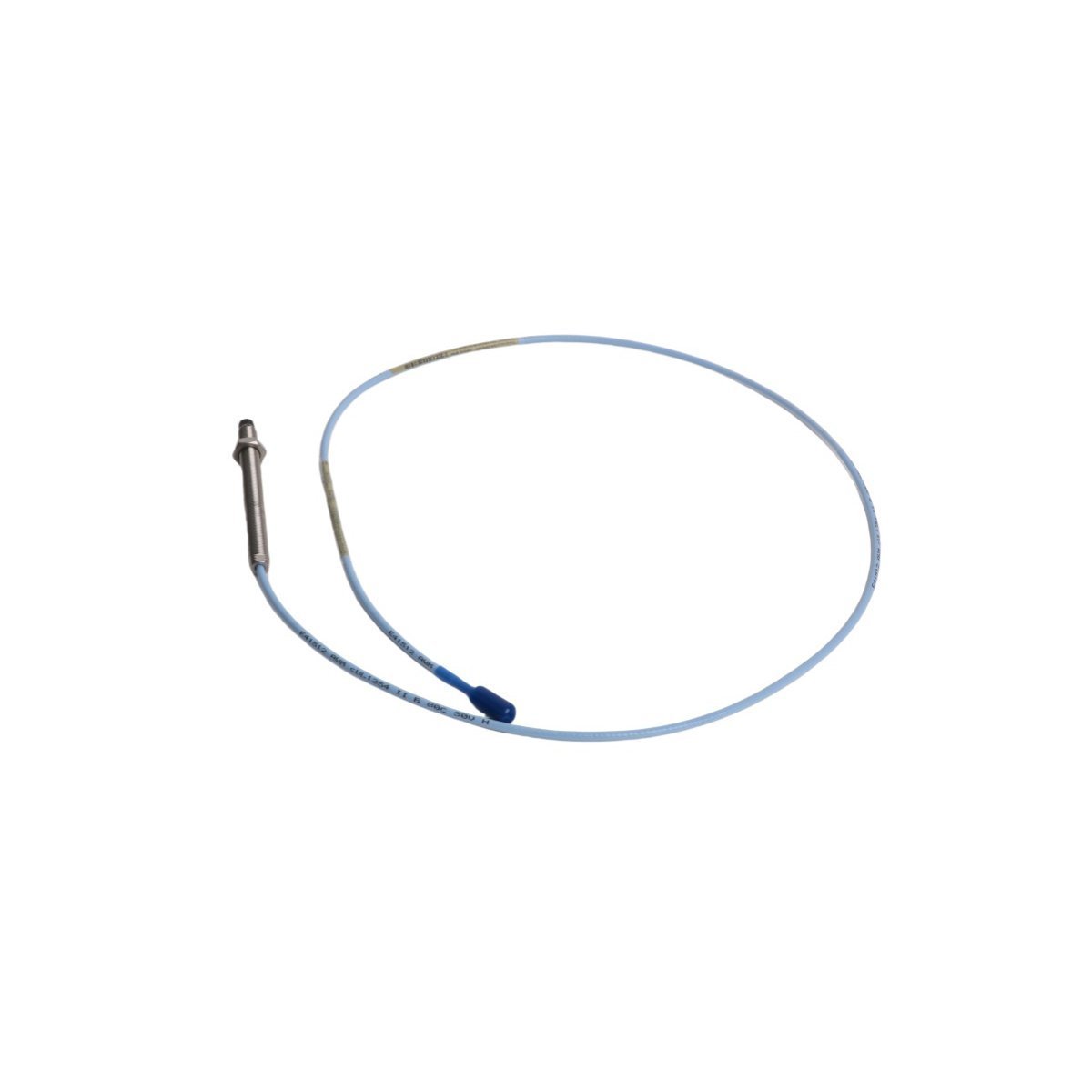
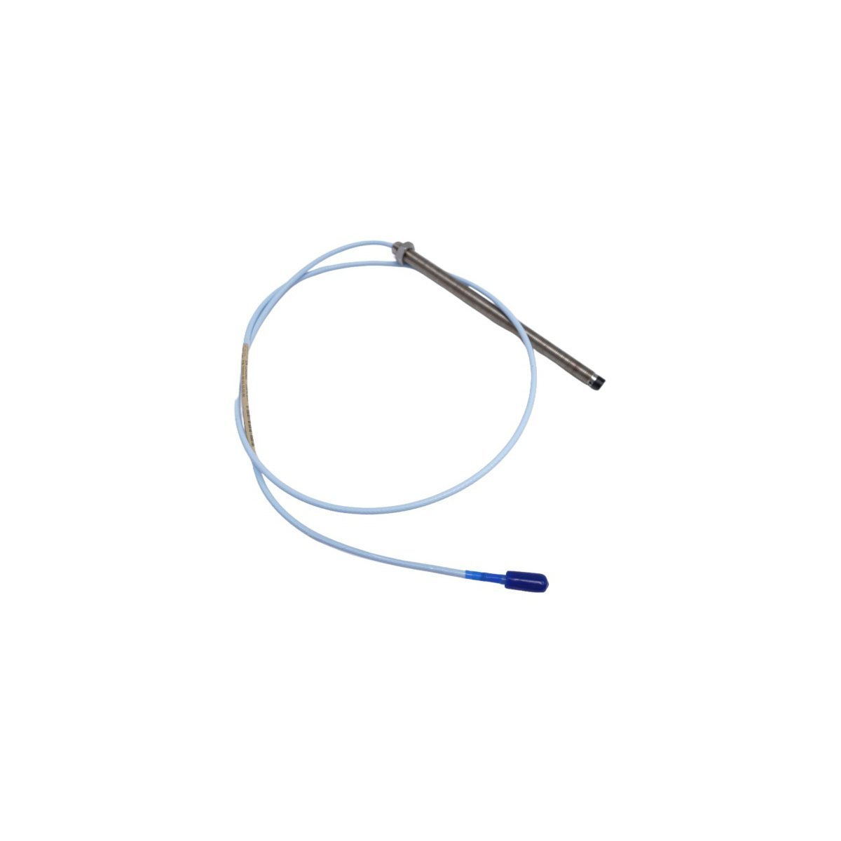
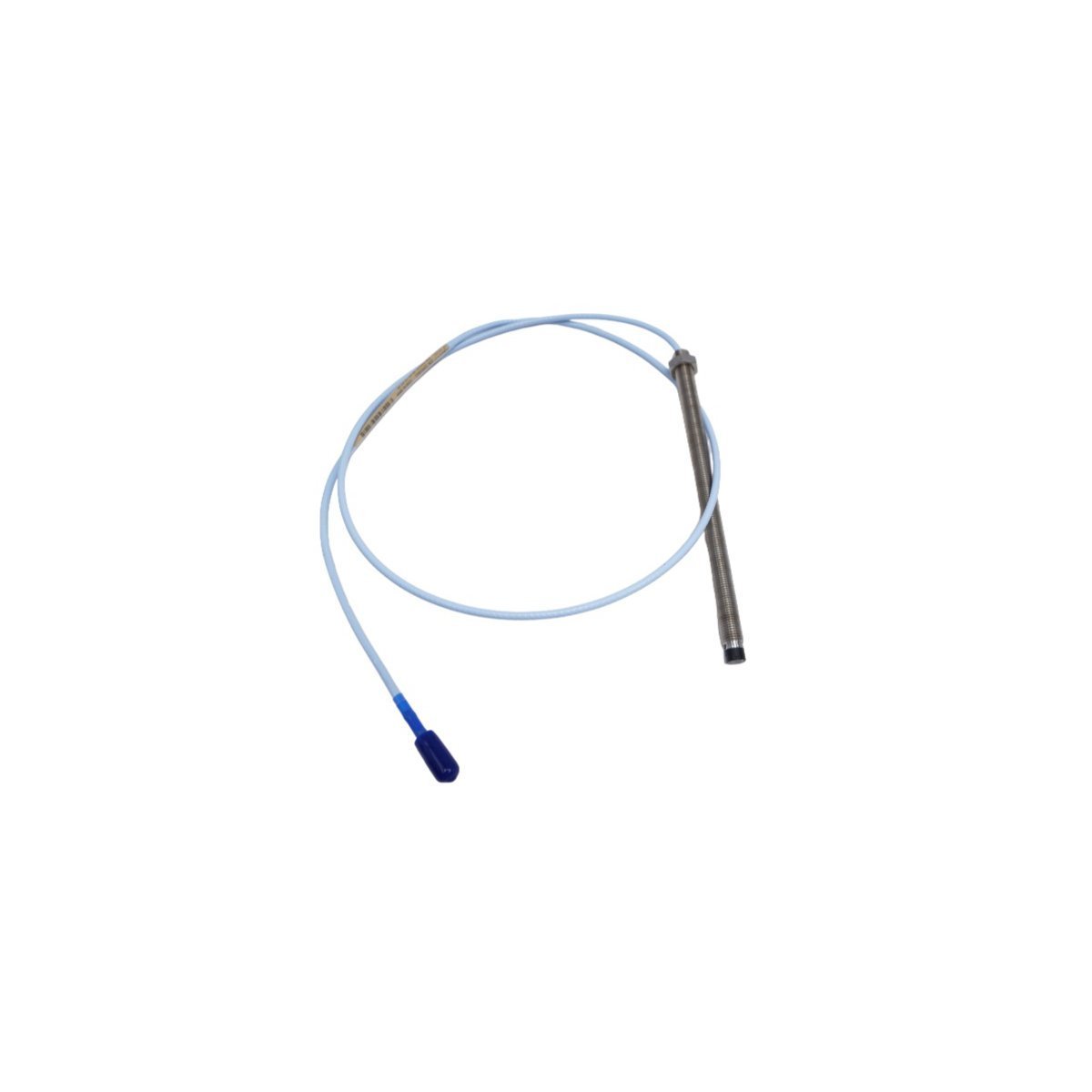
Bently Nevada 330901-10-20-10-02-05 3300 NSv Proximity Transducer System
Sale!
SKU: 330901-10-20-10-02-05
Bently Nevada 330901-10-20-10-02-05 3300 NSv Proximity Transducer System
The Bently Nevada 330901-10-20-10-02-05 probe delivers precision eddy-current monitoring for constrained locations. Brand New original stock with global shipping. Secure this high-performance asset today.
Configured for radial vibration and axial position measurement in TSI platforms, the Bently Nevada 330901-10-20-10-02-05 (330901 Probe) provides direct physical/electrical execution. Operating on eddy-current principles, this hardware component executes non-contact displacement tracking on fluid-film bearing machinery where mechanical clearances are limited. The system converts physical gap variations into proportional electrical signals for direct interface with monitoring modules.
Hardware Specifications
Parameter
Specification
Model
330901-10-20-10-02-05
Brand
Bently Nevada
Origin
USA
Weight
0.06 kg
Dimensions
1.8 x 1.6 x 123 cm
Operating Temp
-35 to +177 deg C
Power Consumption
Driven by external Proximitor Sensor
Average Scale Factor
7.87 V/mm (200 mV/mil)
Linear Range
1.5 mm
Application Target
Shafts smaller than 51 mm, flat targets under 15 mm
HS CODE
8537101190
Machinery Monitoring & TSI Characteristics
The probe utilizes optimized eddy-current probe scaling to ensure linear performance despite narrow target surfaces. During gap voltage validation (-10 VDC targets), the module maintains calibration stability across the 1.5 mm displacement window. The mechanical tip construction and internal winding geometry provide integrated cross-talk suppression, preventing channel interference when multiple probes are installed in tight radial proximity. This enables clean data acquisition for rotor dynamics analysis without signal degradation from adjacent structural metalwork.
Frequently Asked Questions
Q: What are the target physical constraints for this specific probe model?
A: The probe is designed for constrained installations, specifically target shafts under 51 mm in diameter or flat axial targets under 15 mm where standard 5 mm or 8 mm probes experience side-view interference.
Q: How is the gap voltage verified during commissioning?
A: Initial physical gap setting must be checked with a digital multimeter to confirm a nominal -10 VDC baseline, representing the midpoint of the 1.5 mm linear measurement range when connected to the matching Proximitor Sensor.
Field Installation Guidelines
Cable Routing Constraints: Maintain a minimum bend radius of 25.4 mm for the coaxial extension cable to prevent signal attenuation or internal dielectric failure.
Shielding and Grounding: Ensure the coaxial outer shield is isolated from the conduit or machine casing. Earth grounding must be executed exclusively at the monitor rack terminal block to prevent ground loops.
Thread Engagement: Ensure correct mechanical thread engagement when mounting into bracketry or housings. Avoid over-torqueing the locknuts to prevent structural damage to the outer sleeve.
Isolation from External Fields: Route probe leads through dedicated, grounded metal conduits separate from high-voltage AC power wiring to minimize electromagnetic interference.
The 330101-00-75-20-02-00 Bently Nevada 3300 XL Proximity Probe is available in Brand New condition with Original Stock tracking and Global Shipping. Maintain critical machinery vibration metrics now.
Buy the genuine Bently Nevada 330102-00-25-10-02-CN 8mm eddy-current proximity probe. Fully configured with a 3/8-24 UNF thread, 2.5-inch case, 1.0-meter integrated cable, and -CN explosive atmosphere certification pathways. Stocked and ready for express global shipping.
Order the Bently Nevada 330103-13-23-05-02-00 proximity probe from our secure industrial stock. This 3300 XL 8 mm series sensor offers a reverse-mount configuration for precise TSI machinery protection loops. Brand New unit package with global logistics support. Request an automated quote today.
Secure the Bently Nevada 330101-00-08-10-11-00 proximity probe from our original stock inventory. Features an 8 mm tip diameter and a 1.0 m total cable length for exact TSI system machinery monitoring. Brand New product complete with full global shipping solutions. Contact our engineering desk for immediate dispatch procurement.
Purchase factory-new Bently Nevada 330104-00-08-05-01-05 Eddy Current Proximity Sensors. Original parts for turbine vibration monitoring. Fast shipping.
The Bently Nevada 330102-00-36-05-02-05 is an 8mm 3300 XL proximity probe designed for accurate vibration and axial position monitoring in industrial rotating equipment.
The Bently Nevada 330103-00-11-50-02-00 is a 3300 XL 8mm proximity probe featuring a 110mm case and a 5.0-meter total length. This non-contacting sensor provides precision vibration and displacement monitoring for critical rotating machinery in demanding industrial environments.
The Bently Nevada 330104-01-08-15-02-05 is a 3300 XL 8mm metric proximity probe. It features an M10 x 1 threaded body with integrated armor. This transducer provides precise vibration and position data for critical rotating assets.
The Bently Nevada 330101-00-43-15-12-05 is an 8 mm 3300 XL proximity probe with a 3/8-24 UNF thread. It features a 4.3-inch case and a 1.5-meter cable. This sensor provides precise vibration and position data for critical rotating assets in hazardous environments.
The Bently Nevada 330104-00-03-05-02-05 is an 8 mm proximity probe with M10 threads and a 0.5m cable. It provides API 670 compliant vibration and position sensing for rotating assets.
The Bently Nevada 330903-00-03-10-02-05 is a 3300 XL NSv proximity probe featuring M8x1 threads and a 1.0m cable. It provides high-precision vibration sensing for compact industrial applications.
The Bently Nevada 330101-00-64-10-12-05 is an 8mm proximity probe with a 1.0-meter FluidLoc cable. This 3300 XL sensor provides oil-resistant vibration monitoring for critical industrial machinery.
We are committed to protecting your privacy. The information collected here is strictly used to provide the requested quotes, technical support, and relevant industrial automation solutions.