


Sale!
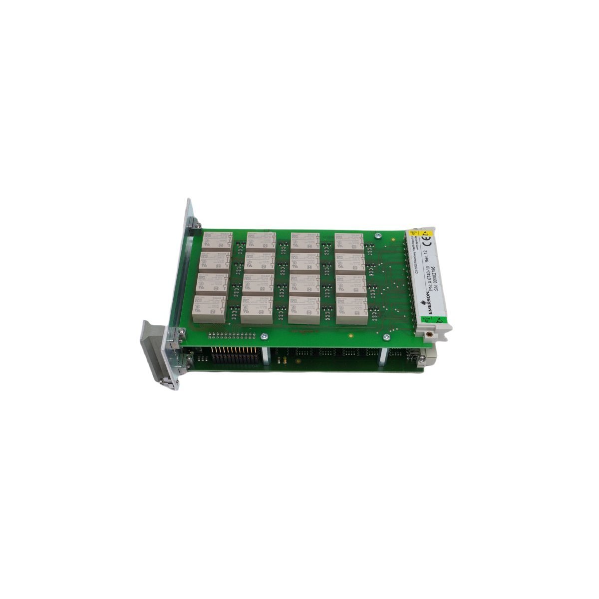
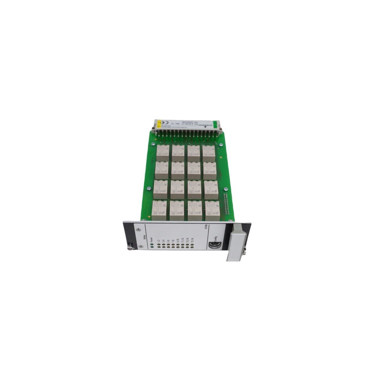
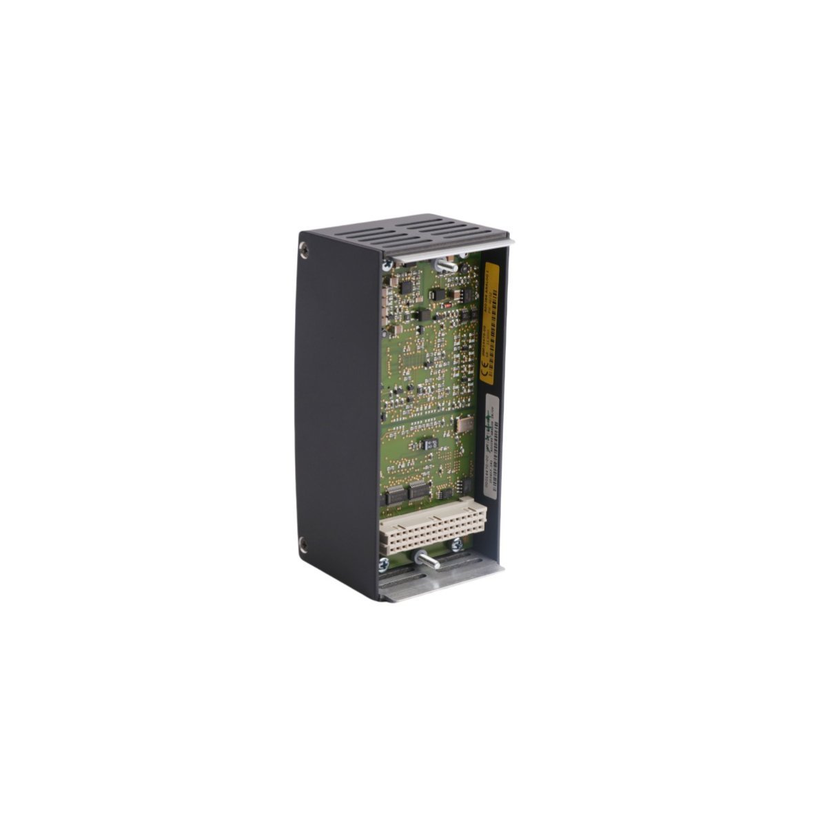
EMERSON A6740-10 AMS 6500 Output Relay Module
The EMERSON A6740-10 is an isolated 16-channel output relay module for the AMS 6500 system. Brand New, Original Stock, with Global Shipping for machinery protection.
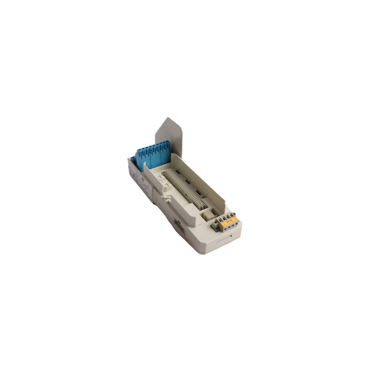
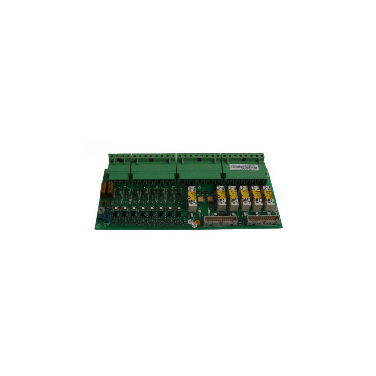
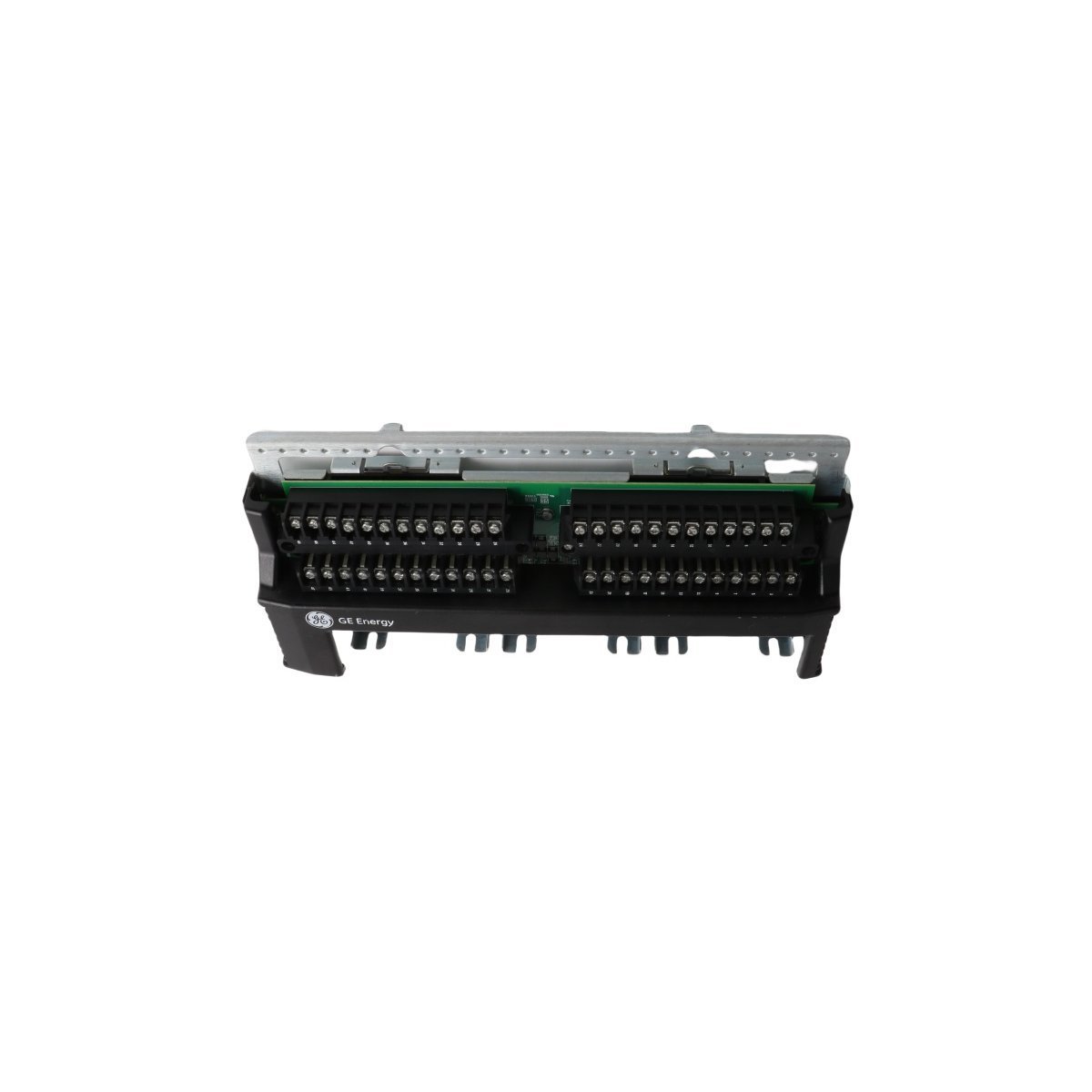
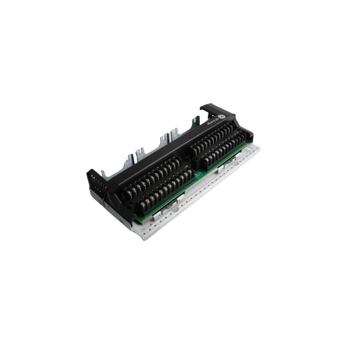
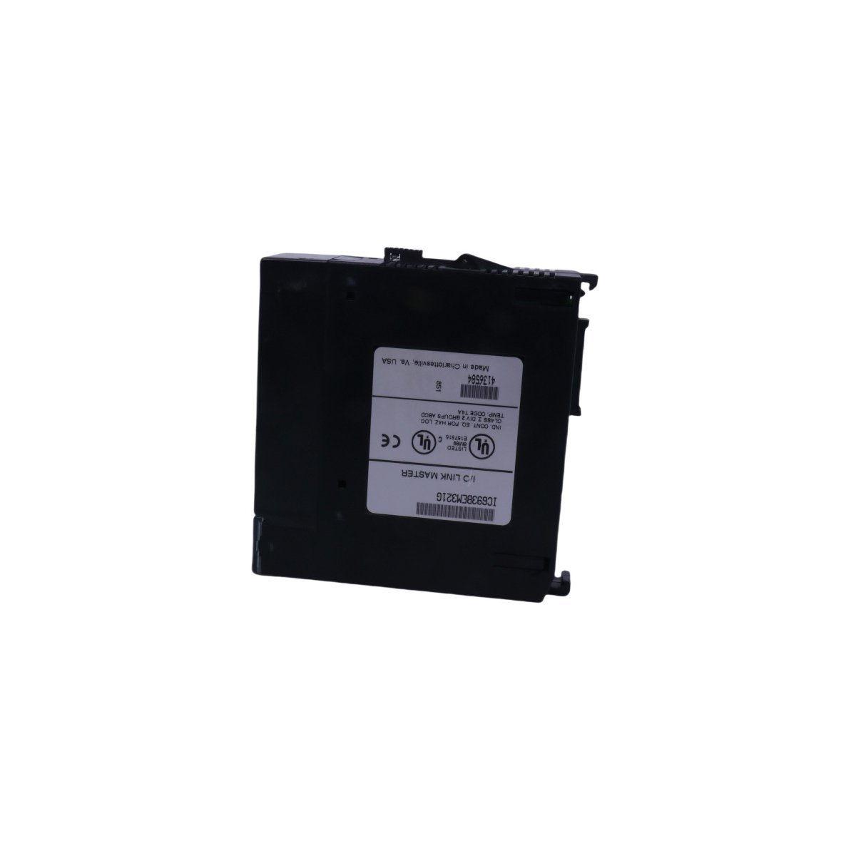
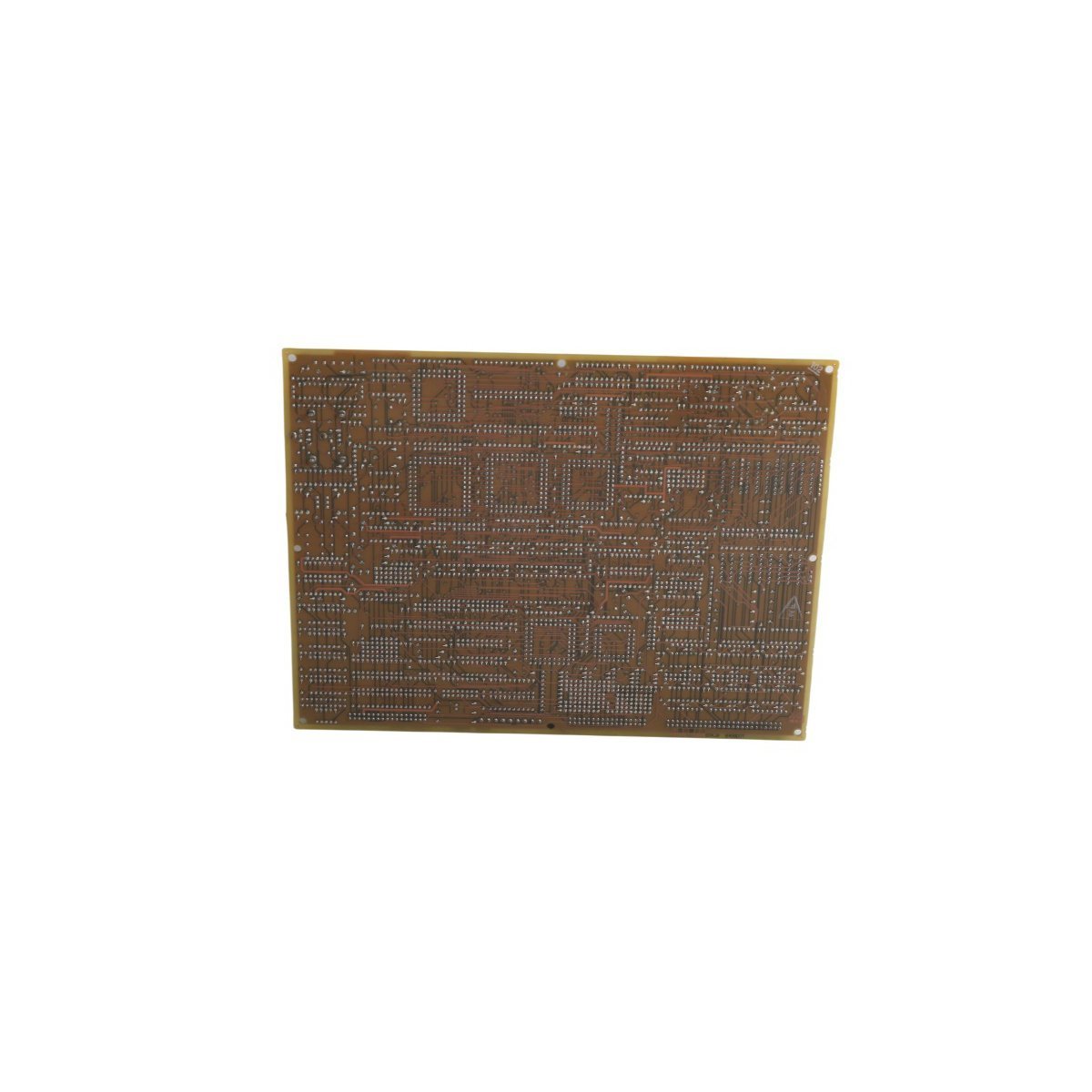
The Allen-Bradley 80190-600-01-R is an industrial optical interface base circuit board. Brand New, Original Stock, Global Shipping available for immediate deployment.
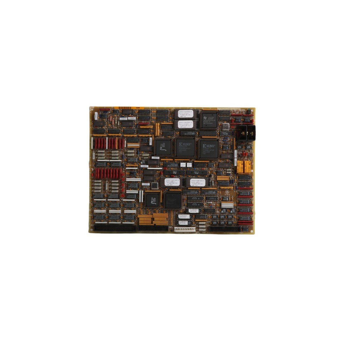
The Allen-Bradley 80190-600-01-R, also cataloged as the 80190-600-01-R PC Board, serves as the primary 80190-600-01-R Optical Interface Base PCB utilized to execute high-speed signal routing and optical-to-electrical signal conversion across Kinetix servo drive platforms. The board functions as a dedicated hardware interface inside the motion controller housing, executing real-time pulse-width modulation processing and feedback data exchange between the main control processor and localized power switching electronics.
| Parameter | Specification |
|---|---|
| Model | 80190-600-01-R |
| Brand | Allen-Bradley |
| Origin | USA |
| Weight | 0.32 kg |
| Dimensions | 25.1 x 19.0 x 2.6 cm |
| Operating Temp | 0 to 55 deg C |
| Power Consumption | Logic-level internal bus consumption |
| Module Type | PC Board / Optical Interface Base |
| System | PLC / Motion Control Drive |
| Communication Service | Localized high-speed optical loop |
| Compliance | RoHS, standard industrial ASCII marking |
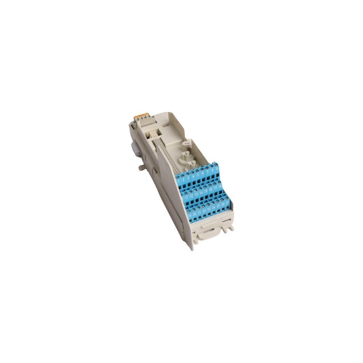
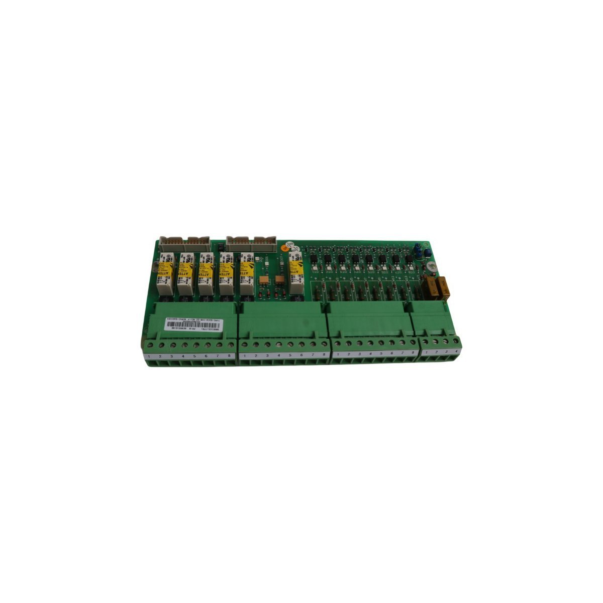
The 80190-600-01-R board integrates dedicated trace geometries and optical transceiver modules optimized for low latency and high I/O density scaling inside multi-axis drive cabinets. By translating external feedback pulses into synchronous internal drive commands, the board maintains data integrity under high-frequency electrical switching noise environments. The localized firmware flash compatibility embedded in the host drive system enforces hardware-level handshake timings, aligning the board’s physical gate driver outputs with the main EtherNet/IP deterministic network commands to prevent axis desynchronization during peak dynamic loads.
Q: What is the primary purpose of the optical interface array on this specific circuit board?
A: The optical components isolate the low-voltage logic processing circuits from the high-voltage power components within the servo drive housing. This physical separation prevents transient voltage spikes from damaging the central processing architecture.
Q: Are there hardware adjustments or potentiometers to calibrate on the board during installation?
A: No. All signal calibration, torque loop parameters, and velocity gains are managed digitally via the Studio 5000 software interface and flashed directly to the host controller memory. The board functions strictly as a fixed physical execution layer.
Q: How is the firmware revision on this printed circuit board managed?
A: The board relies on the firmware flash compatibility of the parent servo drive assembly. Upgrading the drive’s main firmware automatically updates the peripheral routing gate arrays present on the optical interface board.
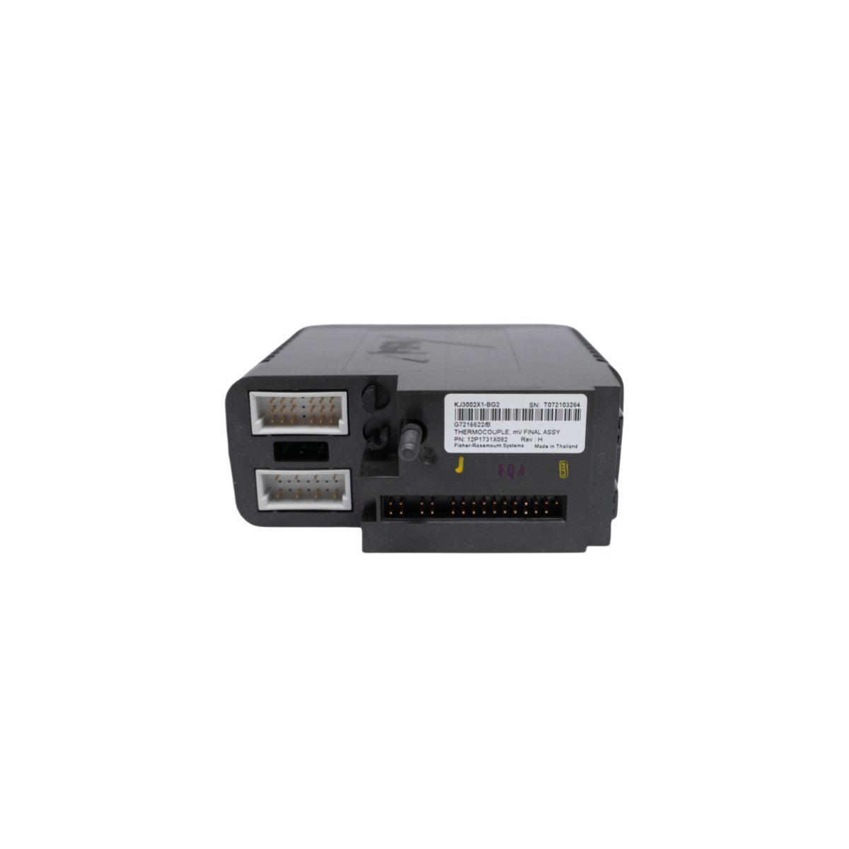
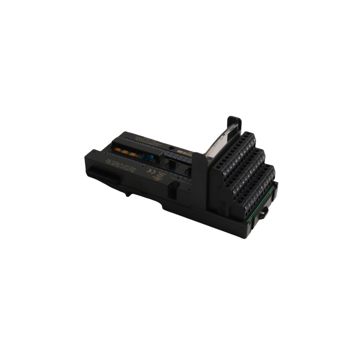
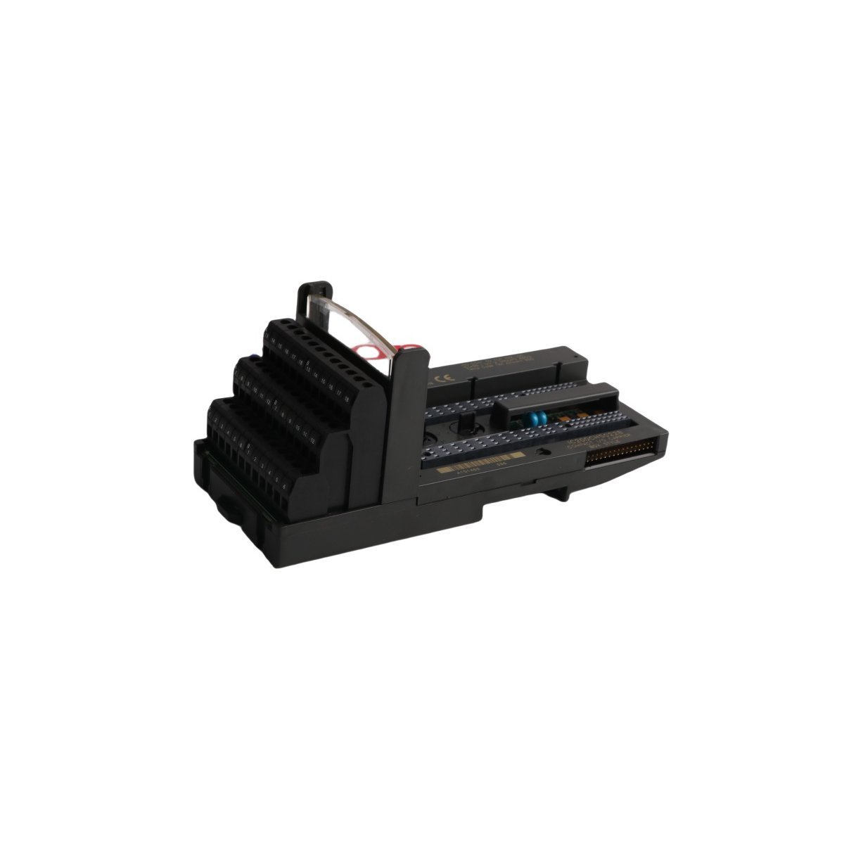
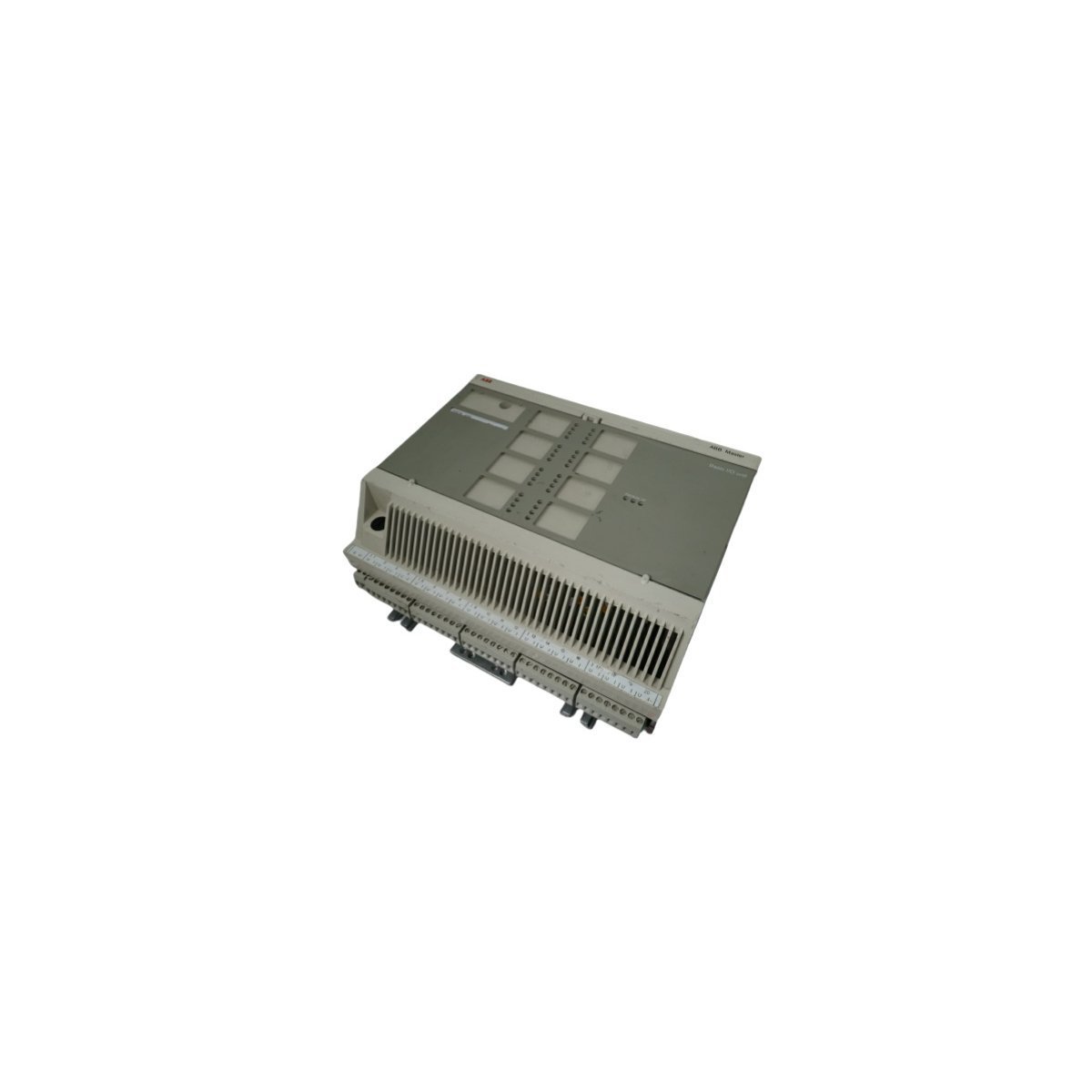
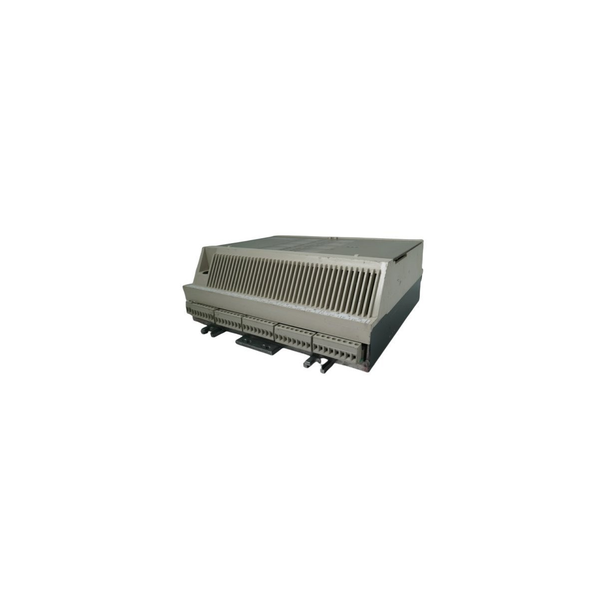
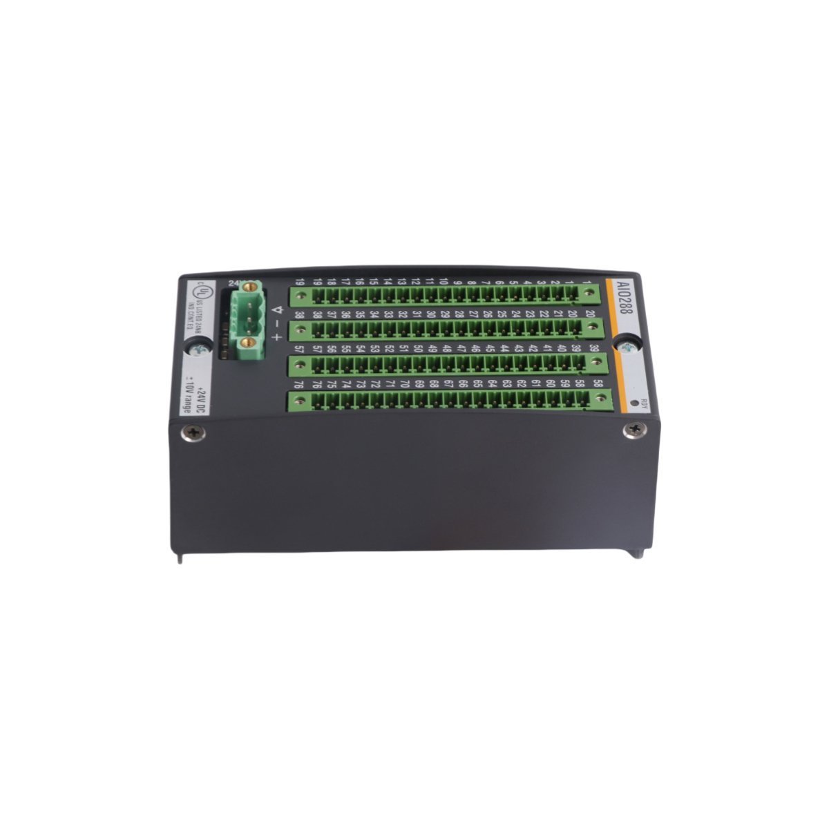
The Emerson DeltaV™ M-series KJ3002X1-BB1 (12P0683X092 / VE3006) is a legacy, high-precision thermocouple and mixed-signal I/O module designed for flexible process control within the DeltaV Distributed Control System (DCS). Capable of reading continuous analog variables alongside discrete status indicators, this modular card features built-in galvanic signal isolation, advanced thermocouple loop-burnout diagnostics, and high-density noise protection. Engineered for direct hot-swappable installation into M-series carriers, it delivers stable, industrial-grade data acquisition for critical temperature, flow, and pressure monitoring loops across harsh, high-interference manufacturing environments.


We are committed to protecting your privacy. The information collected here is strictly used to provide the requested quotes, technical support, and relevant industrial automation solutions.