Sale!
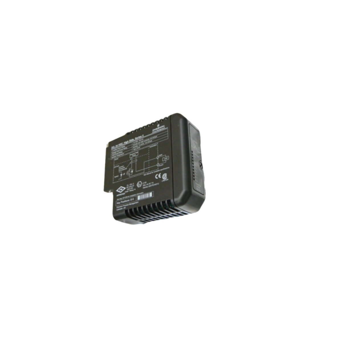
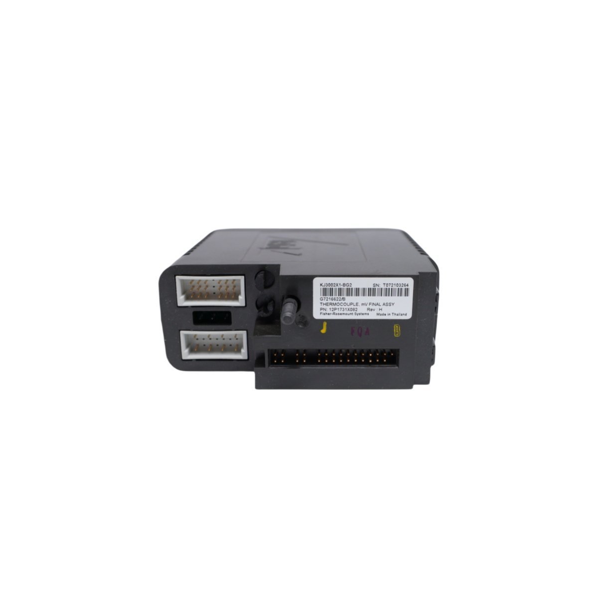
Emerson KJ3002X1-BG2 Thermocouple Module
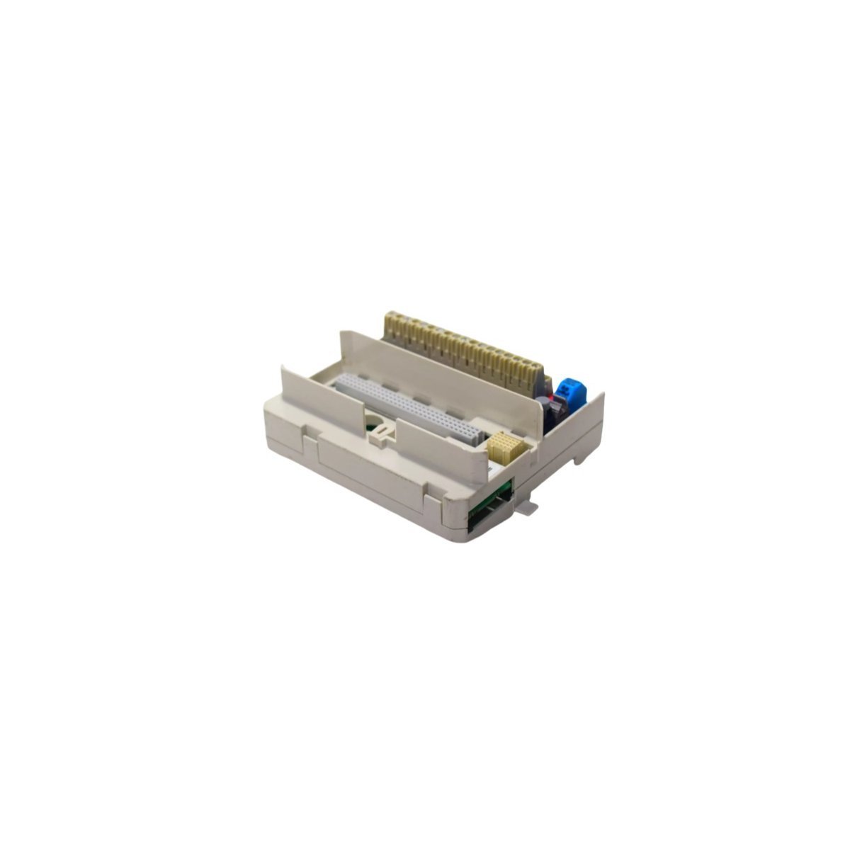
Configured for direct analog signal acquisition in Emerson DeltaV DCS environments, the Emerson KJ3002X1-BG2, also cataloged as the KJ3002X1-BG2 Thermocouple Module, provides direct physical/electrical execution.
Hardware Specifications
| Parameter | Specification |
|---|---|
| Model | KJ3002X1-BG2 |
| Brand | Emerson |
| Part Number | 12P1731X022 |
| System Reference | VE4003S5B1 |
| Range of Product | DeltaV M-series I/O Subsystem |
| Module Type | Thermocouple Module |
| Channels | 8 Channels |
| Origin | USA |
| Weight | 0.2 kg |
| Dimensions | 8.1 x 7.9 x 8.8 cm |
| HS Code | 8537101190 |
| Status | Discontinued (Dec 31, 2018) |
Process Control and DCS Characteristics
- Converts millivolt inputs from field thermocouples into digitized temperature values for system controller processing.
- Features integrated cold junction compensation (CJC) algorithms to maintain signal accuracy across varying cabinet temperatures.
- Utilizes channel-to-channel isolation architecture to eliminate ground loops and reject common-mode voltage spikes across industrial field cabling.
- Incorporates 4-20 mA HART loop protocol carrier compatibility across system backplane interfaces for extended instrument diagnostic passthrough.
Frequently Asked Questions
Q: How does the KJ3002X1-BG2 module perform cold junction compensation?A: Cold junction compensation is maintained via internal thermal sensors embedded on the terminal block assembly, correcting for ambient variations at the wiring termination point.Q: Can the module be inserted or removed while the terminal base is powered?A: Yes, DeltaV M-series I/O modules support power-on insertion and removal (removal under power) when installed on compatible I/O carrier bases.Field Installation Guidelines
- Secure the module onto the DeltaV M-series I/O carrier until the locking mechanisms fully engage with the backplane base.
- Ensure shielded thermocouple wiring is grounded at a single point to prevent high-frequency noise interference on low-millivolt input channels.
- Maintain a minimum bending clearance for field wiring to prevent mechanical stress on terminal connectors.