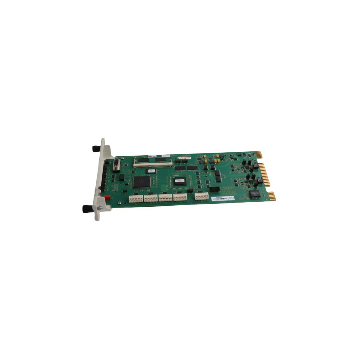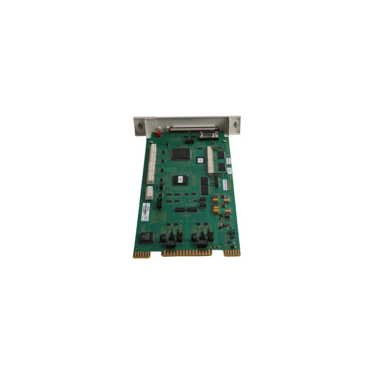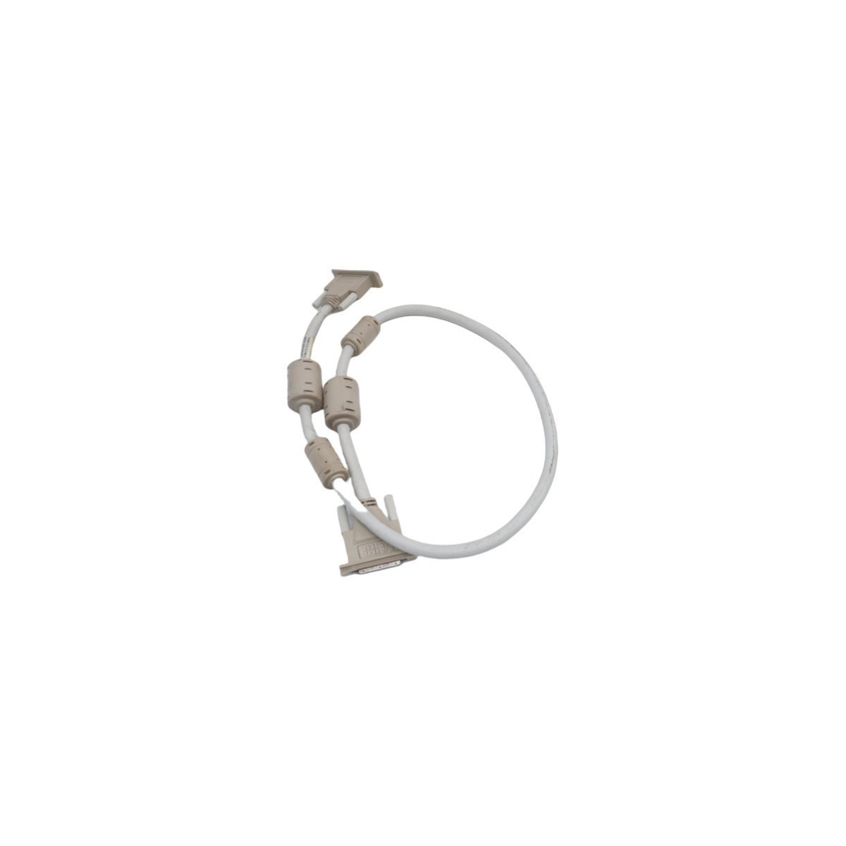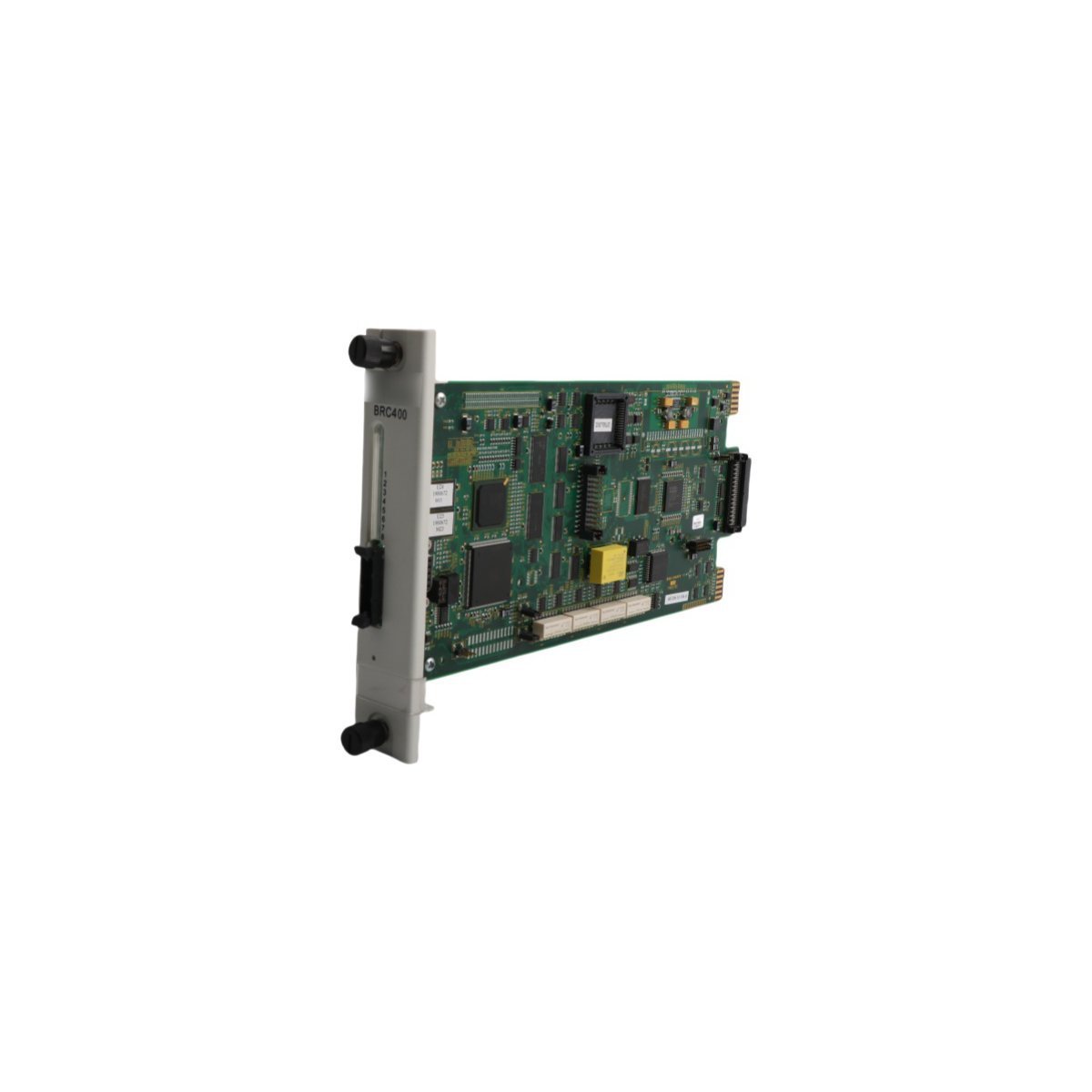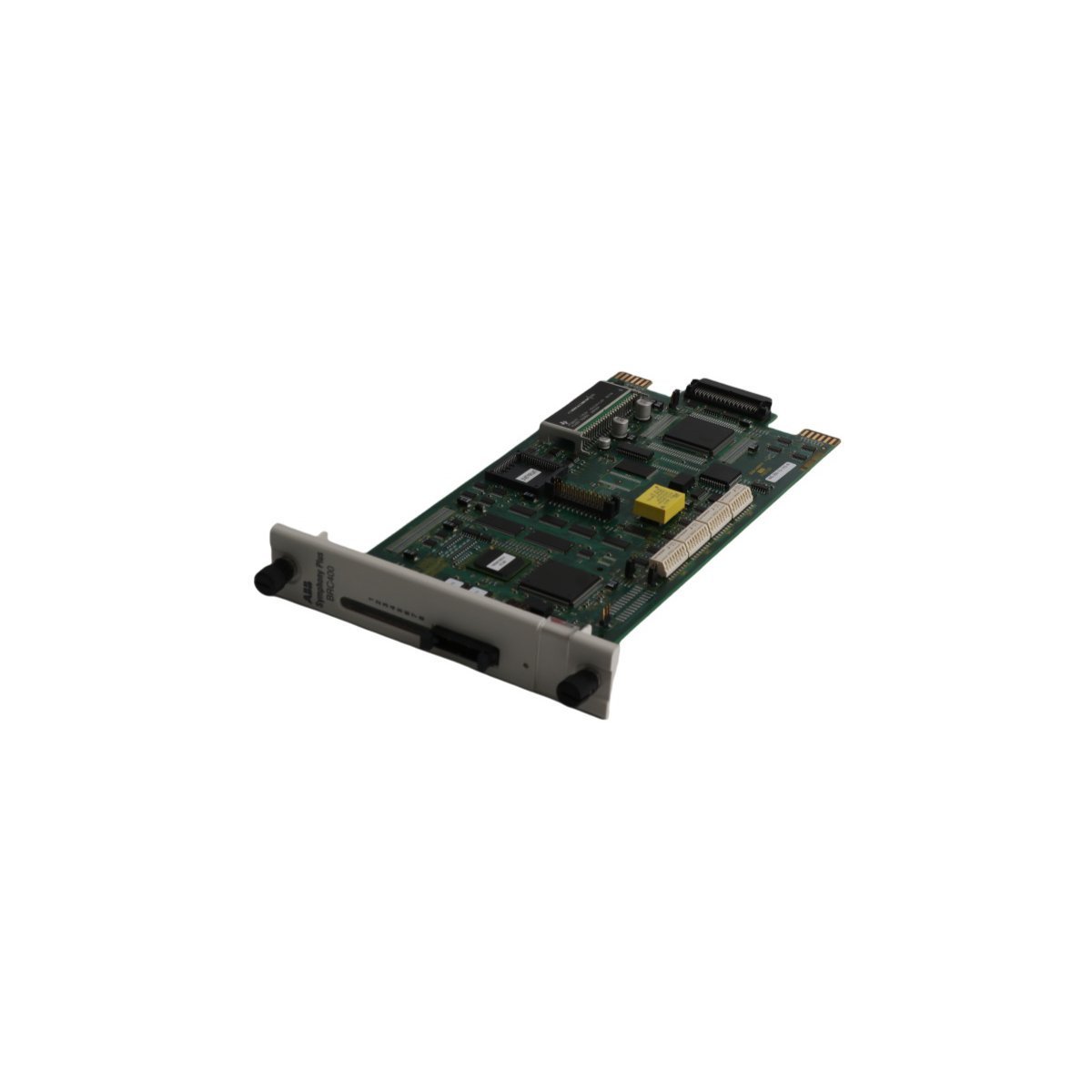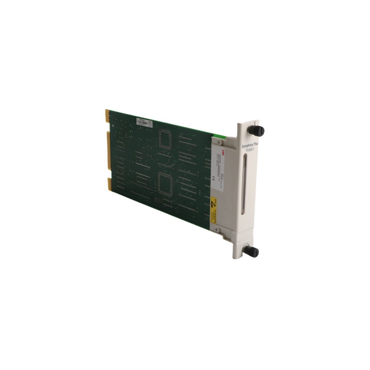
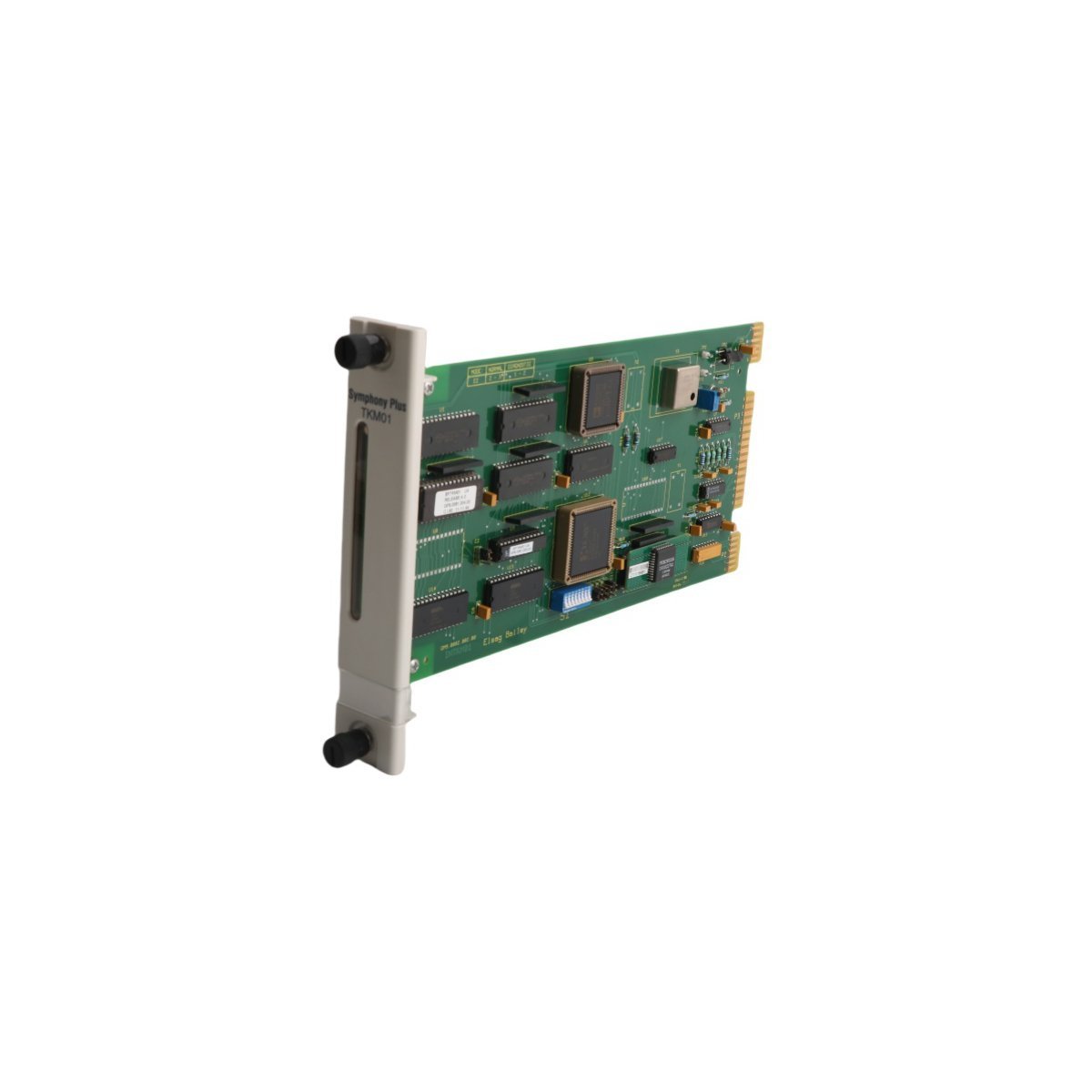
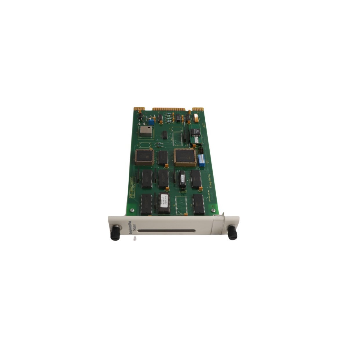
The ABB SPTKM01 is a Symphony Plus SOE Time Keeper Master designed for high-resolution event timestamping and synchronization. This rugged DCS module features non-volatile flash memory and a wide operating temperature range, providing essential diagnostic data for complex industrial automation systems.
The ABB SPTKM01 functions as a high-precision Sequence of Events (SOE) Time Keeper Master within the Symphony Plus DCS architecture. This module provides a centralized time synchronization reference, ensuring that every event across the distributed control network receives an accurate and consistent timestamp. By maintaining a microsecond-level resolution, the SPTKM01 allows engineers to reconstruct complex fault sequences with absolute chronological integrity.
Equipped with high-capacity, non-volatile flash memory, the module serves as a reliable repository for historical event logs. This data retention capability proves indispensable for root cause analysis (RCA) and regulatory compliance in power generation and heavy process industries. The SPTKM01 operates independently of the central controller for time-critical tasks, which preserves system bandwidth and enhances overall processing efficiency.
Core Capabilities and Integration
Precision Synchronization: Delivers ultra-accurate time distribution across multiple DCS nodes to eliminate temporal drift.
Industrial Protocol Support: Utilizes industry-standard communication protocols to ensure seamless interoperability with existing automation infrastructure.
Rugged Environmental Design: The circuit board is engineered to operate reliably in harsh conditions, maintaining full functionality in temperatures ranging from -20°C to +60°C.
Sequence Management: Advanced logic processing enables the module to prioritize and order high-frequency event bursts during system-wide disturbances.
Streamlined Configuration: Compatible with ABB’s suite of software tools, the module supports rapid deployment and remote diagnostic monitoring.
Data Integrity: Non-volatile storage prevents data loss during power cycles, securing critical forensic information for post-event analysis.
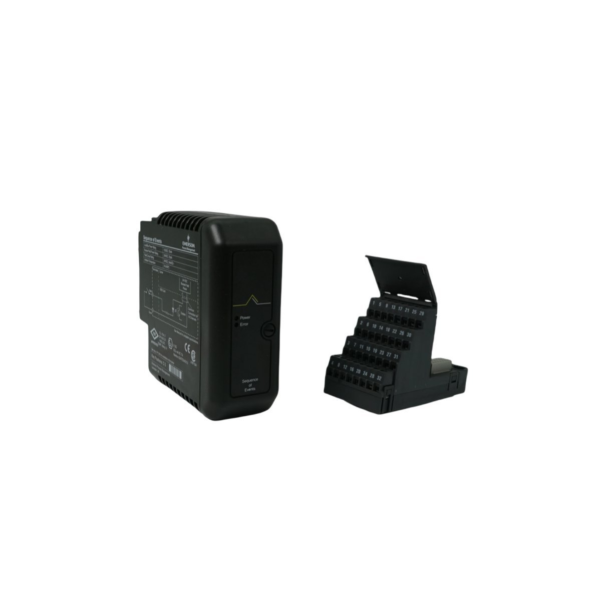
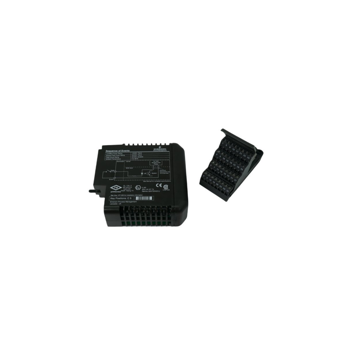
The Emerson KJ3008X1-BA1 12P2293X052, also cataloged as the KJ3008X1-BA1 Sequence Events Module, operates as a dedicated hardware component for high-resolution discrete event timestamping and digital state acquisition within Emerson DeltaV M-series I/O Subsystem platforms.
Hardware Specifications
Parameter
Specification
Model
KJ3008X1-BA1 12P2293X052
Brand
Emerson
Product Range
DeltaV M-series I/O Subsystem
Module Type
Sequence Events Module
Origin
USA
Weight
0.28 kg
Dimensions
4.3 x 12.5 x 10.5 cm
Operating Temp
-40 to 70 deg C
Power Consumption
12 VDC at 150 mA (local bus)
HS Code
8537101190
Lifecycle Status
Discontinued (Dec 31, 2018)
Process Control and DCS Characteristics
Interfaces directly with 4-20 mA HART loop protocol architectures and discrete field contacts via DeltaV I/O carrier backplanes.
Features integrated channel-to-channel isolation to prevent ground loop noise propagation across adjacent signal paths.
Leverages hardware-level cold junction compensation (CJC) algorithms across paired terminal blocks during thermal transients.
Executes millisecond-accurate sequence-of-events logging to capture contact state transitions before transferring data to DeltaV controllers.
Frequently Asked Questions
Q: Does the KJ3008X1-BA1 module support removal under power within a DeltaV I/O carrier?A: Yes, the module supports Removal and Insertion Under Power (RIUP) without disrupting communications or field wiring on adjacent I/O cards.Q: How is time synchronization maintained across multiple Sequence Events Modules?A: Time synchronization is maintained via the DeltaV M-series local bus backplane driver, which aligns module event counters with the system master clock.
Field Installation Guidelines
Secure the module onto the dedicated DeltaV M-series I/O carrier terminal block slot until the retention latch locks fully.
Ground all field cable shields at the carrier earth bus bar using short, low-impedance conductor connections.
Maintain separation between low-voltage field contact signal lines and high-voltage power conduits inside the enclosure.
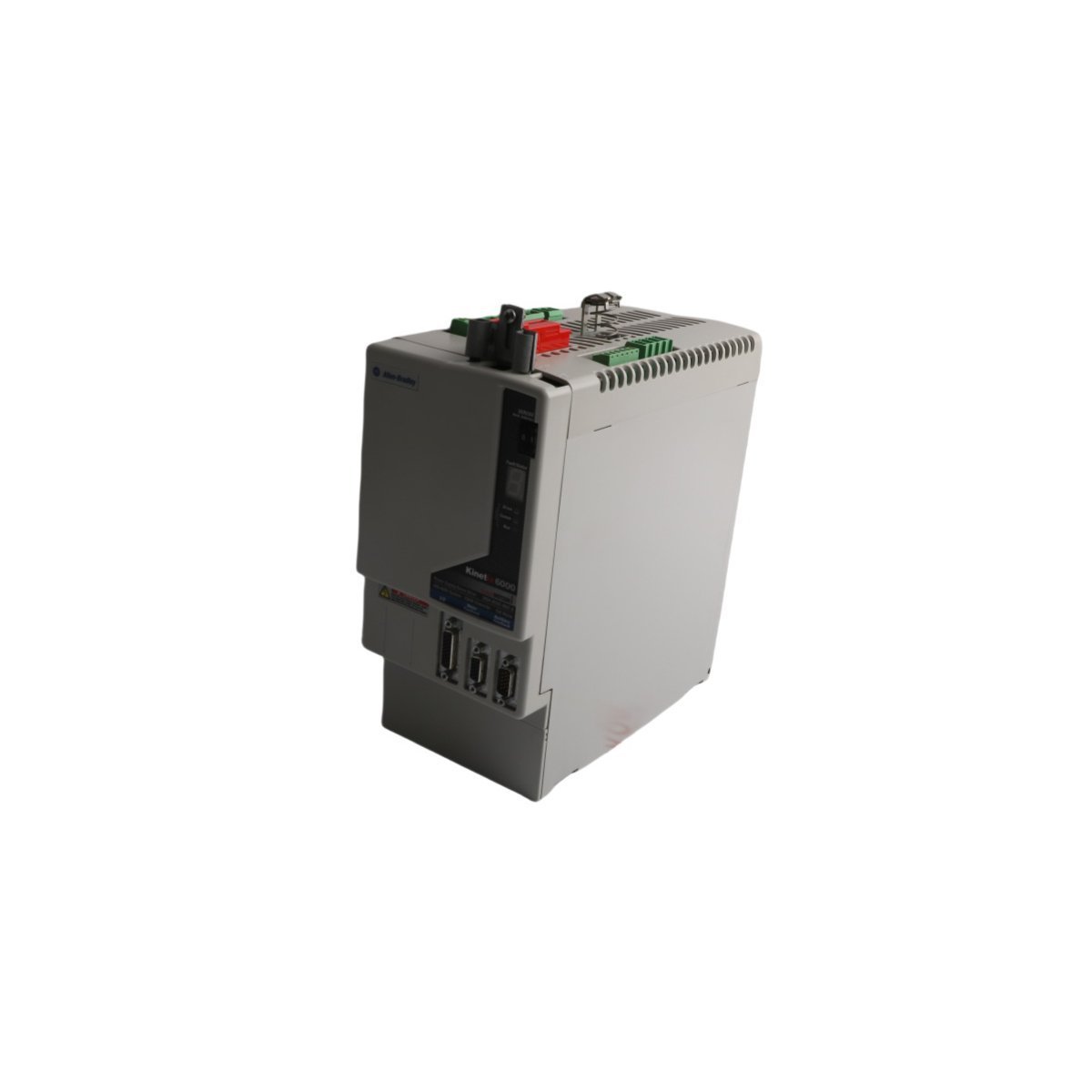
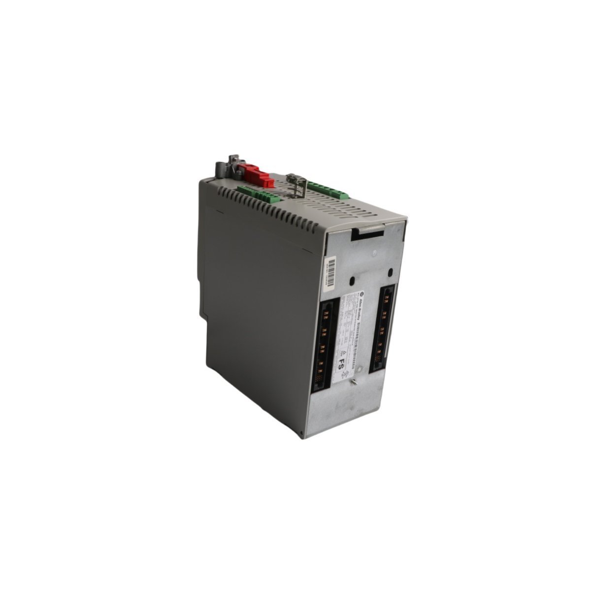
The Allen-Bradley 2094-BC02-M02-M, also cataloged as the 2094-BC02 Integrated Axis Module, operates as a dedicated hardware component for AC line power rectification and axis motion execution within Kinetix 6000 multi-axis servo systems. It converts three-phase AC input voltage into a regulated DC bus supply while simultaneously controlling a single servo axis inverter output. The module features embedded hardware-based Safe Torque-Off (STO) logic, solid-state motor short-circuit monitoring, and direct interface links for multi-axis power sharing across external drive rails.
Hardware Specifications
Parameter
Specification
Model
2094-BC02-M02-M
Brand
Allen-Bradley
Origin
USA
Module Type
Integrated Axis Module (IAM)
System Architecture
PLC / Kinetix 6000 Multi-Axis Servo
Input Voltage Range
360-480 VAC, 3-Phase
Converter Power Rating
15 kW / 23 A
Inverter Power Rating
6.6 kW / 14.6 A
Heat Dissipation
44 W (Converter), 72 W (Inverter)
Short Circuit Rating
200000 A (Fused), 65000 A (Circuit Breaker)
Integrated Safety
Safe Torque-Off (STO)
Control Input Fuse Recommendation
Bussmann FNQ-R-10 (10 A)
DC Bus Power Fuse Recommendation
Bussmann FWJ-40A
HS Code
8537101190
Dimensions
12.7 cm x 29.2 cm x 25.4 cm
Weight
5.6 kg
Operating Temp
0 to 50 deg C
EtherNet/IP and SERCOS Deterministic Network Integration
The module coordinates real-time synchronization using EtherNet/IP and SERCOS communication interfaces. High-speed position and velocity loop data flow deterministically between the central Logix controller and the drive inverter stages over cyclic network slots. Internal timing hardware synchronizes multi-axis motion cycles to reduce axis skew. Integrated diagnostic registers transmit voltage levels, thermal status, phase loss detections, and motor fault flags back to the controller without dedicated external sensor wiring.
Frequently Asked Questions
Q: What branch circuit protection fuses are mandated for input power isolation?A: Control input power loops require Bussmann FNQ-R-10 (10 A) fuses, while the DC bus power link requires Bussmann FWJ-40A fuses to achieve a 200000 A short-circuit current rating (SCCR).Q: How does the integrated Safe Torque-Off (STO) function operate electronically?A: The STO circuit directly disables the gate drive signals to the output power transistors (IGBTs), preventing the inverter from generating motor torque without removing main line input power from the power supply stage.Q: What are the thermal dissipation metrics during partial load operations?A: Under standard partial load conditions, the internal converter section dissipates 44 W of heat, and the internal inverter section dissipates 72 W of heat into the cabinet enclosure.
Field Installation Guidelines
Enclosure Clearance and Thermal Mounting: Mount the module vertically on a flat, grounded surface inside an IP54 or NEMA 12 industrial enclosure. Maintain a minimum vertical clearance of 50 mm above and below the chassis to allow unimpeded convection airflow through the heat sink assembly.
Grounding and Shielding Protocols: Connect the module ground lug directly to the central enclosure ground bus using a low-impedance stranded copper conductor. Motor power cables must utilize 360-degree continuous metallic braid shielding clamped directly to the chassis ground plate to suppress high-frequency electromagnetic interference (EMI).
Power and DC Bus Terminal Wiring: Ensure three-phase 360-480 VAC line power is disconnected before accessing input terminal blocks. Verify correct terminal polarity on shared DC bus link bars when interconnecting additional follower axis modules on the power rail. Torque all power terminal screw connections to the vendor-specified mechanical limits.
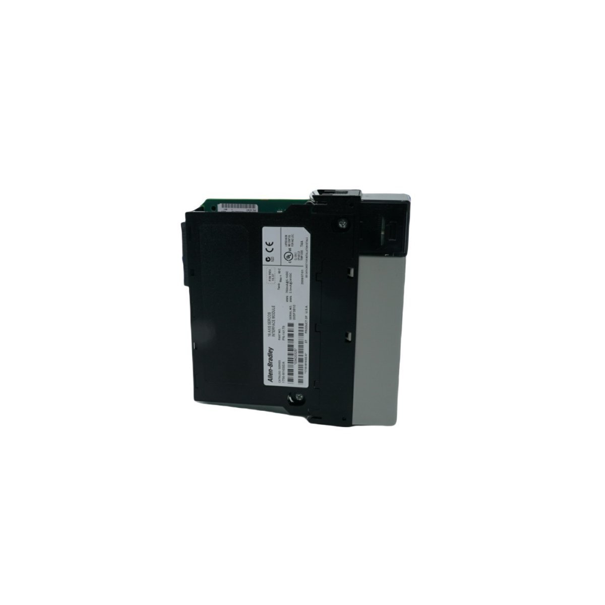
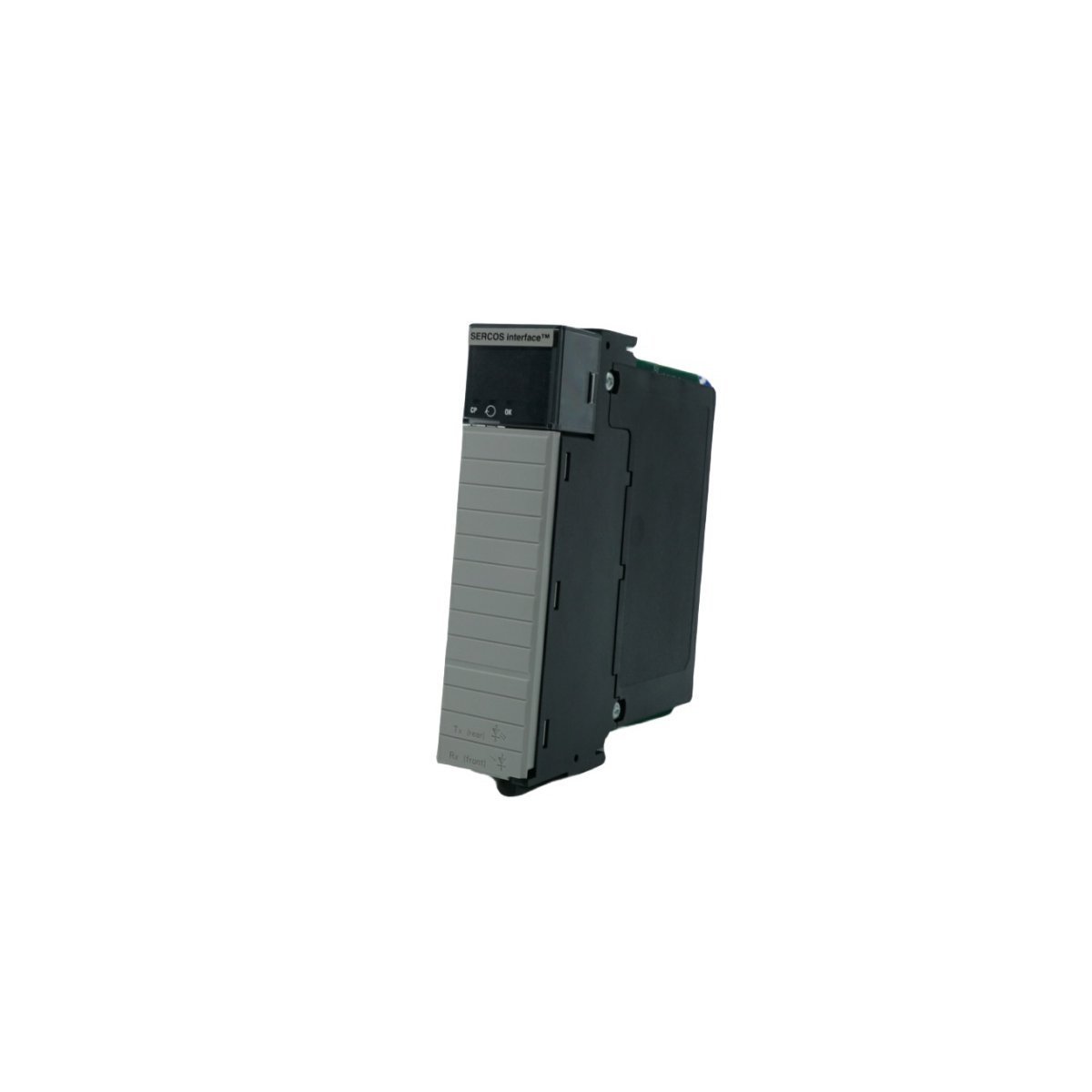
Configured for high-speed motion synchronization in ControlLogix systems, the Allen-Bradley 1756-M16SE (1756-M16SE SERCOS interface Module) provides direct physical and electrical execution for multi-axis servo drive command distribution.
Hardware Specifications
Parameter
Specification
Model
1756-M16SE
Brand
Allen-Bradley
Origin
USA
Weight
0.22 kg
Dimensions
3.5 cm x 14 cm x 14.5 cm
Operating Temp
Standard industrial range
Power Consumption
Backplane dependent
Data Rate
4 Mbps or 8 Mbps
Axis Capacity
16 axes per module
PLC Control and Communication Characteristics
The 1756-M16SE utilizes high-speed backplane bus communication velocity to manage deterministic data exchange between the ControlLogix CPU and remote servo drive nodes. By leveraging digital fiber-optic SERCOS interfaces, the module achieves I/O density scaling that minimizes signal propagation latency across 16 managed axes. Furthermore, the module supports firmware flash compatibility, which allows for site-specific motion algorithm updates without physical hardware replacement. This deterministic network structure ensures that position, velocity, and torque command loops maintain sub-millisecond synchronization even in high-density drive configurations.
Frequently Asked Questions (FAQ)
Q: What are the primary limitations when configuring the SERCOS ring topology for the 1756-M16SE?A: The ring topology is limited by the physical length of the fiber-optic cabling and the total number of connected nodes; you must ensure the total loop latency does not exceed the configured cycle time (0.5 ms or 1.0 ms) to maintain deterministic operation.Q: Is the 1756-M16SE module capable of hot-swapping within an active ControlLogix chassis?A: The module supports standard ControlLogix hot-swap procedures; however, removing the module will immediately drop the SERCOS ring communication, causing all connected servo drives to transition to their programmed fault state.
Field Installation Guidelines
To begin with, confirm the ControlLogix chassis backplane is powered down; subsequently, insert the 1756-M16SE into a designated slot and secure it using the integrated module locking screws to ensure proper backplane contact.
In addition, route the SERCOS fiber-optic cables following the ring or linear topology requirements;Â meanwhile, maintain the minimum bend radius of the fiber to prevent micro-fractures that induce signal loss.
Furthermore, ensure all fiber-optic connectors are clean and free of contaminants before insertion into the module transceivers;Â consequently, this prevents optical attenuation that could lead to intermittent link failures.
Finally, configure the module addressing and axis scaling within the control software;Â by doing so, you ensure the controller can successfully establish the SERCOS communication cycle with the downstream Kinetix drives.
The ABB SPNIS21, also cataloged as the SPNIS21 Bailey Network Interface Module, operates as a dedicated hardware component for network connectivity and data exchange within Symphony Plus DCS platforms.
Hardware Specifications
Parameter
Specification
Model
SPNIS21
Brand
ABB
Origin
SWEDEN
Weight
0.24 kg
Dimensions
3.5 x 31.5 x 17.5 cm
Operating Temp
Standard Industrial Grade
Power Consumption
Not specified
Product Range
Symphony Plus
Deterministic Network Connectivity and Firmware
The integration of this module into the Symphony Plus environment relies on specific backplane bus communication protocols to ensure deterministic data exchange. Furthermore, users must verify firmware flash compatibility before initial deployment to ensure synchronization with the central controller's scanning cycle. Consequently, the module manages I/O data throughput by maintaining high-speed signal polling, which is subsequently critical for maintaining scan time integrity across the distributed control network. In addition, strict adherence to these firmware requirements is necessary to prevent communication bottlenecks; moreover, this process is vital for preserving the overall deterministic nature of the I/O processing loop, thereby ensuring continuous and stable data synchronization.
Frequently Asked Questions (FAQ)
Q: Does the SPNIS21 support hot-swapping during system operation?A: No, this module does not support hot-swapping. The backplane power must be isolated and the system de-energized before physical insertion or extraction to prevent electrical damage to the module interface and backplane pins.Q: How can network-related communication latency be minimized?A: Ensure that the network interface is correctly configured within the control loop parameters and that the communication cable shielding is properly terminated to the system earth to prevent electromagnetic interference.
Field Installation Guidelines
Physical Mounting: Install the module into the designated slot within the cabinet backplane. Ensure the retention screws or locking mechanisms are tightened to maintain structural stability.
Signal Shielding: All network and communication cabling must be shielded. Terminate shields to the designated common ground point at the cabinet entry to prevent ground loops.
Wiring Separation: Maintain clearance between communication interface cables and high-voltage power conduits to mitigate the risk of inductive noise coupling into the data stream.
Visual Inspection: Before finalizing installation, inspect all pins on the module and backplane for oxidation or mechanical deformation.
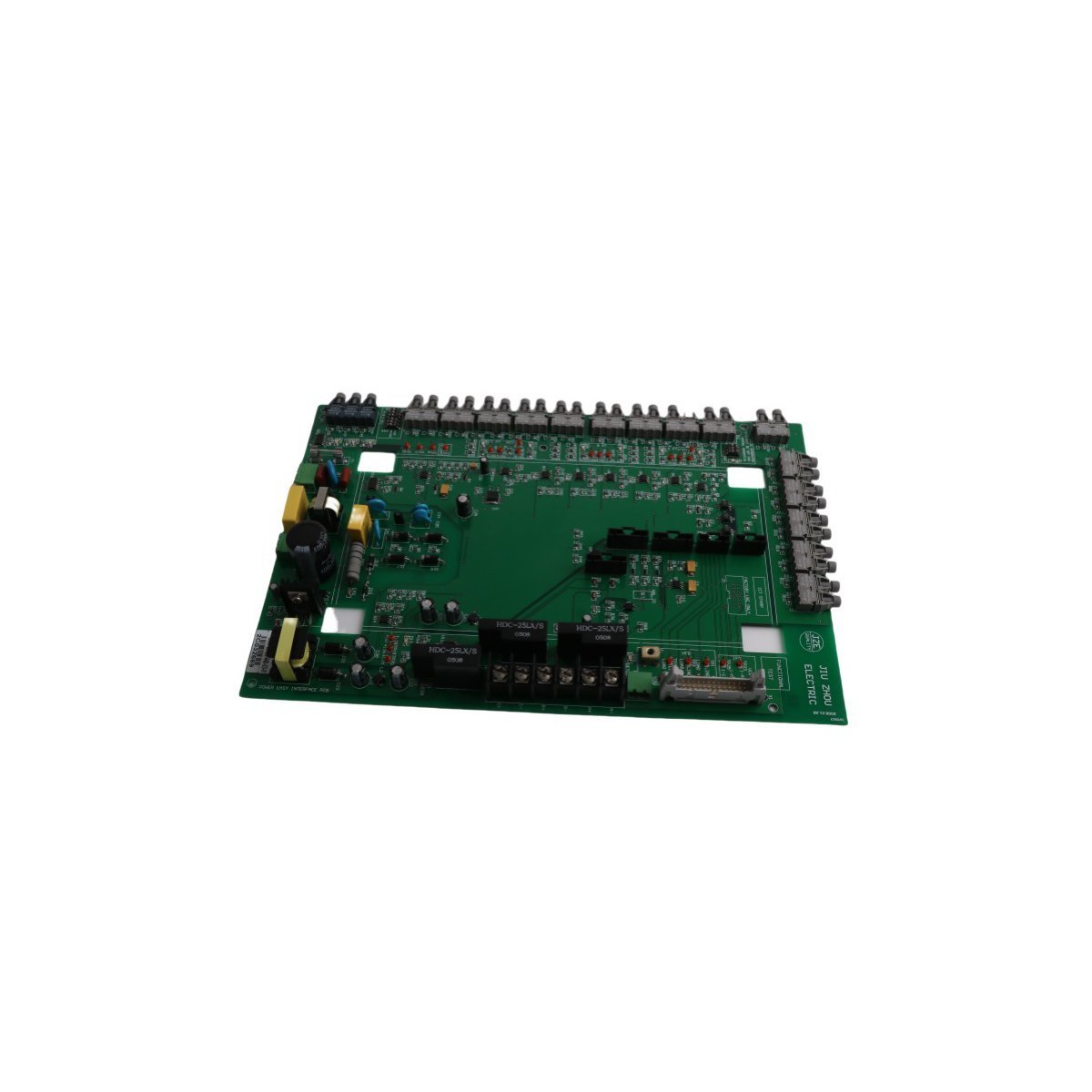
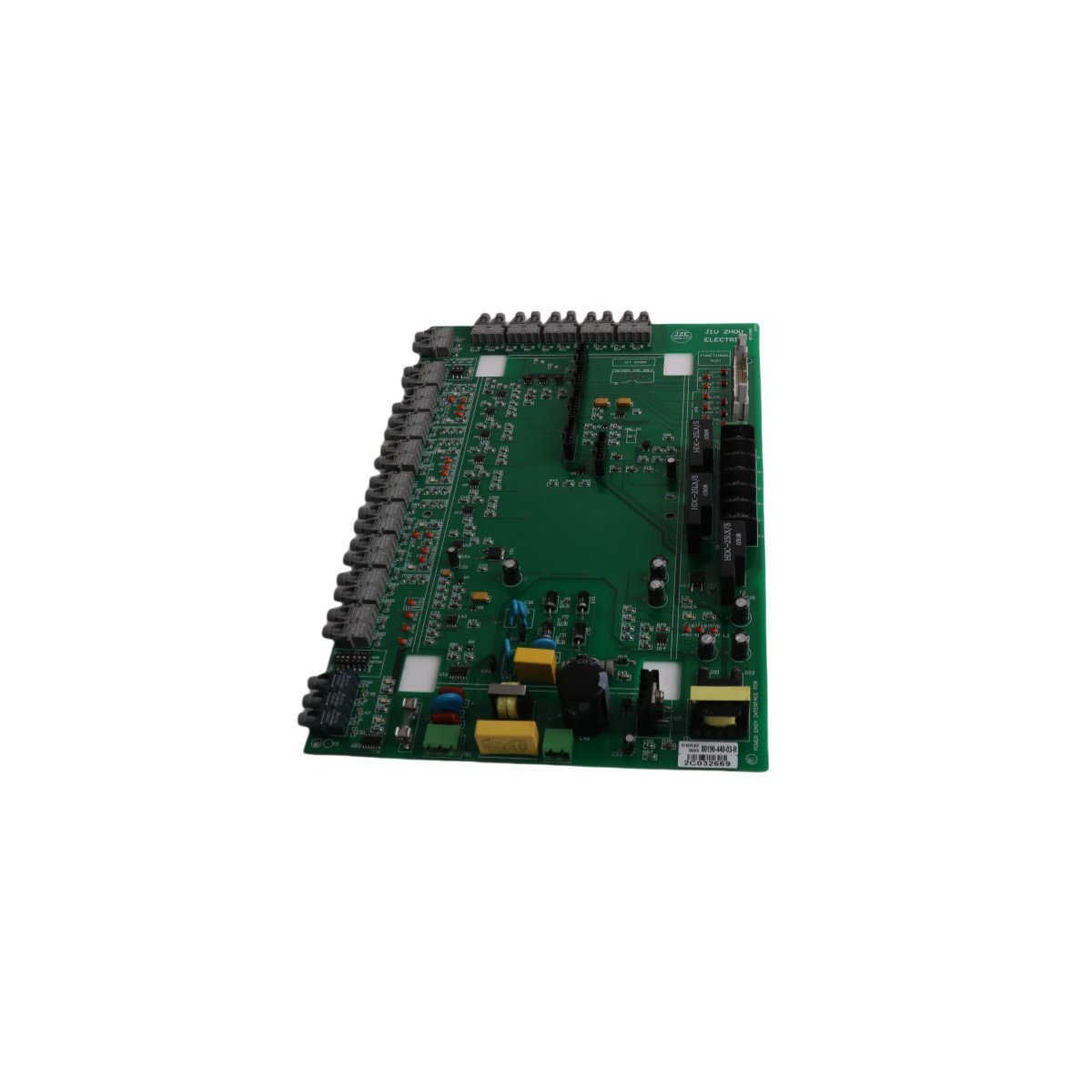
The Allen Bradley 80190-440-02-R interface board provides reliable signal management and logic control for SMC Flex soft starter motor protection systems.
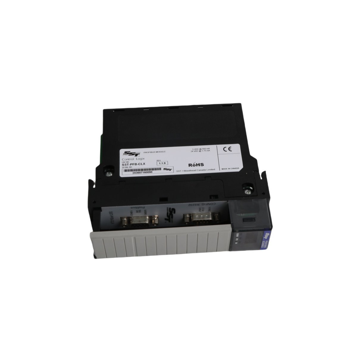
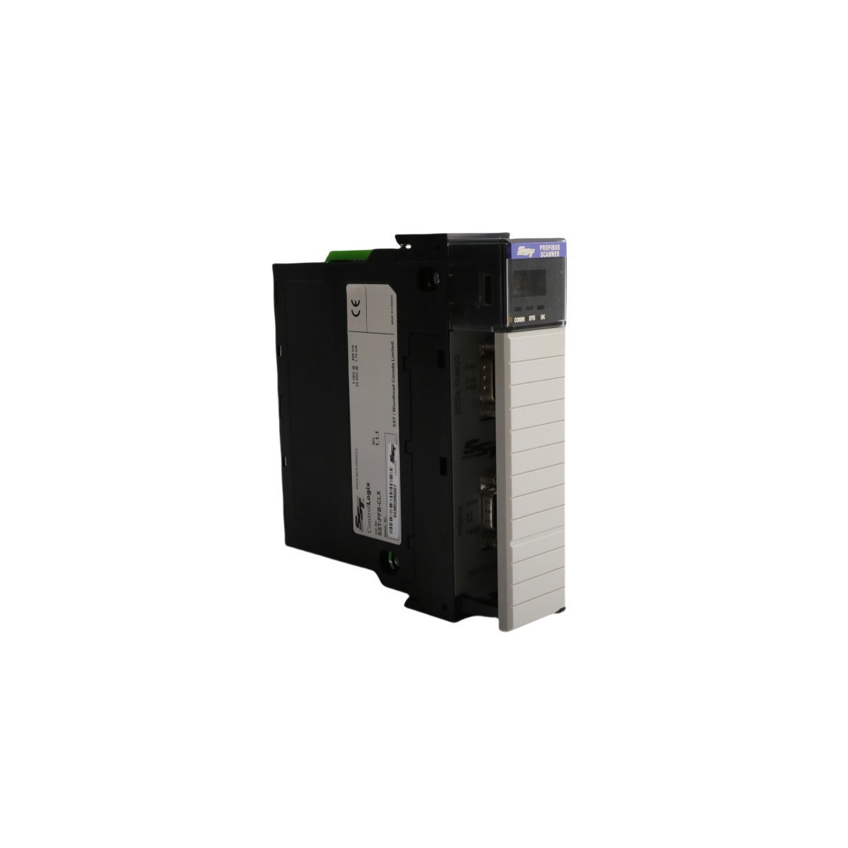
The Allen-Bradley SST-PFB-CLX is a ControlLogix PROFIBUS DP Master Scanner module that provides seamless integration between Rockwell controllers and PROFIBUS networks. It supports up to 12 Mbps data rates and features a dedicated configuration port for easy system setup.
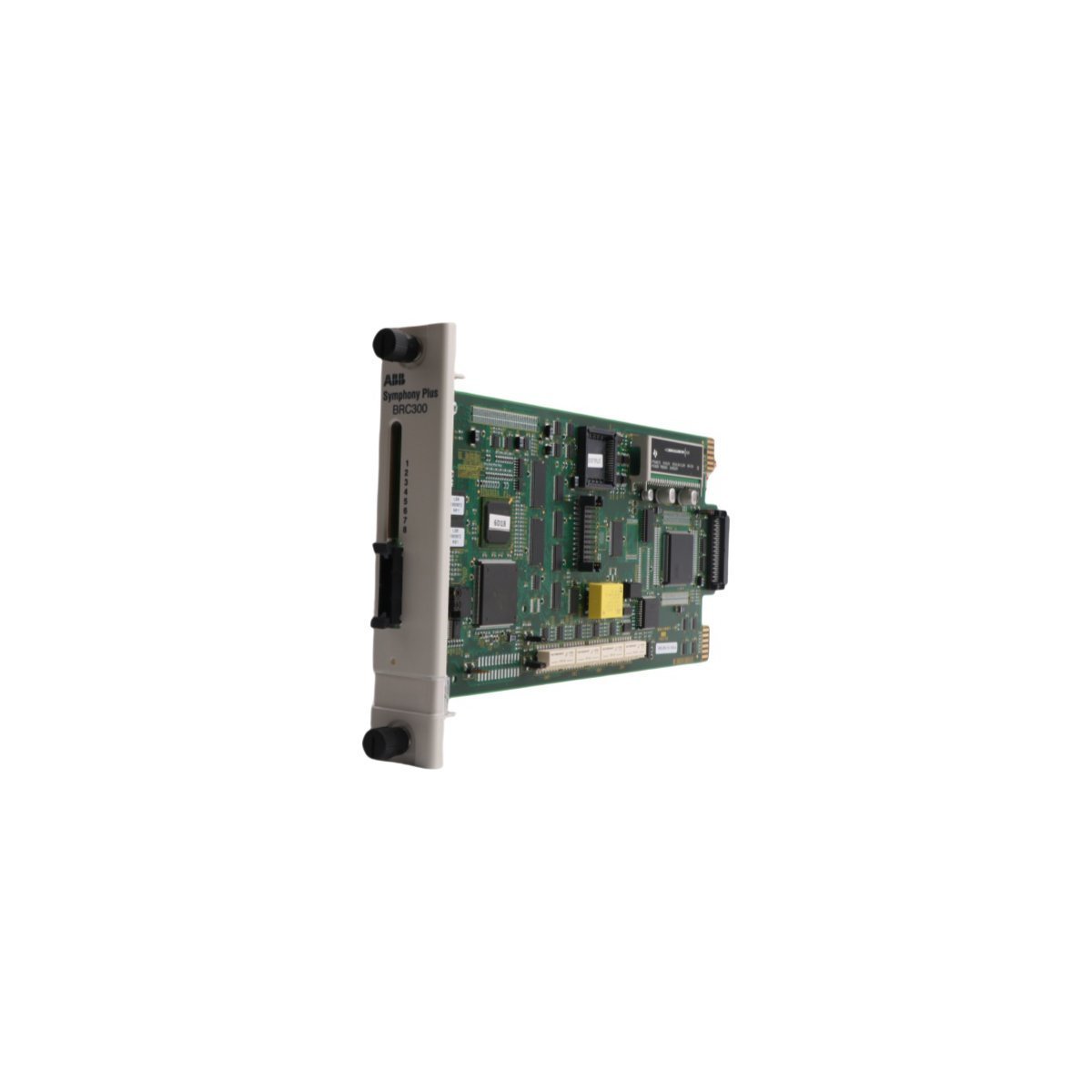
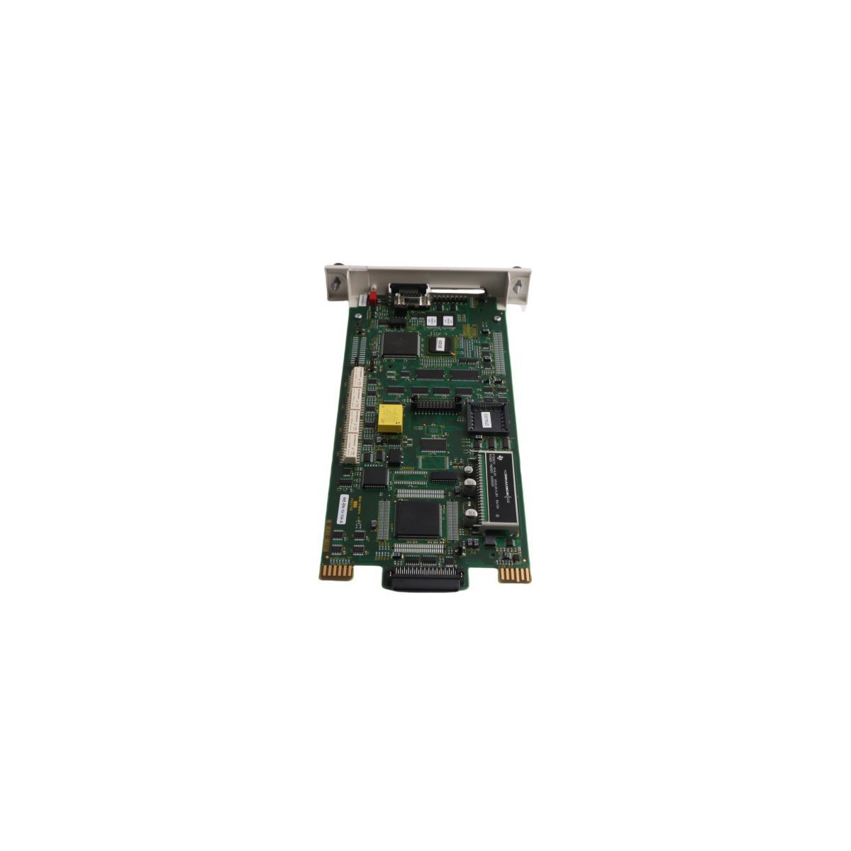
The ABB SPBRC300 is a high-performance central bridge controller for Symphony Plus DCS. Featuring 16 digital inputs, 8 digital outputs, and dual Ethernet/Modbus support, this Swedish-engineered unit provides reliable, real-time logic execution and seamless network integration for demanding industrial automation.
The ABB SPASI23 is a high-performance analog input module for Symphony Plus DCS environments. It delivers precise signal conversion, robust electrical isolation, and seamless backplane integration for reliable industrial process monitoring and control.
The ABB SPSED01 is a 16-channel Sequence of Events (SOE) digital input module for Symphony Plus systems. Weighing 0.36kg, this Swedish-engineered component provides millisecond-accurate event recording and robust diagnostic features. It ensures reliable data acquisition for complex industrial process monitoring and fault analysis.
The ABB SPDSI14 is a 16-channel, 48 Vdc digital input module for Symphony Plus and Bailey Infi 90 systems. Weighing 0.2kg, this Swedish-made module offers high-density signal acquisition, dielectric-grade housing, and full CE/UL compliance for reliable industrial DCS performance.
The ABB TK851V010 (3BSC950262R) is a 10-meter prefabricated communication cable for AC 800M controllers. It ensures high-speed data integrity and easy installation in DCS environments. This genuine Swedish-made cable offers superior shielding and durability for demanding industrial automation tasks.
The ABB SPBRC400 is a Symphony Plus Bridge Controller featuring expanded memory and advanced diagnostic capabilities.Designed for high-performance DCS environments, it provides reliable logic processing and Ethernet routing for complex industrial automation systems.
We are committed to protecting your privacy. The information collected here is strictly used to provide the requested quotes, technical support, and relevant industrial automation solutions.