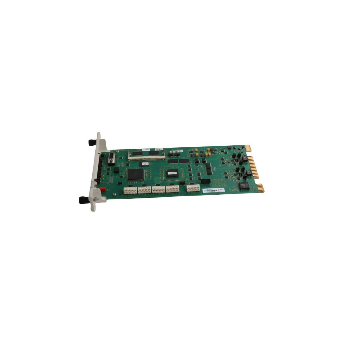
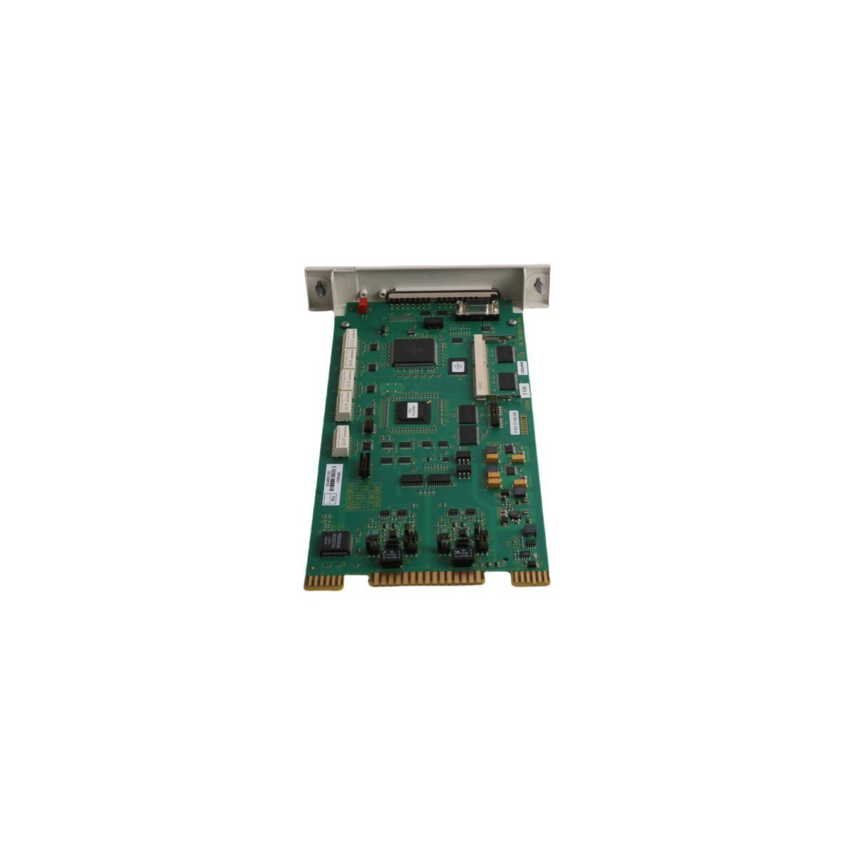
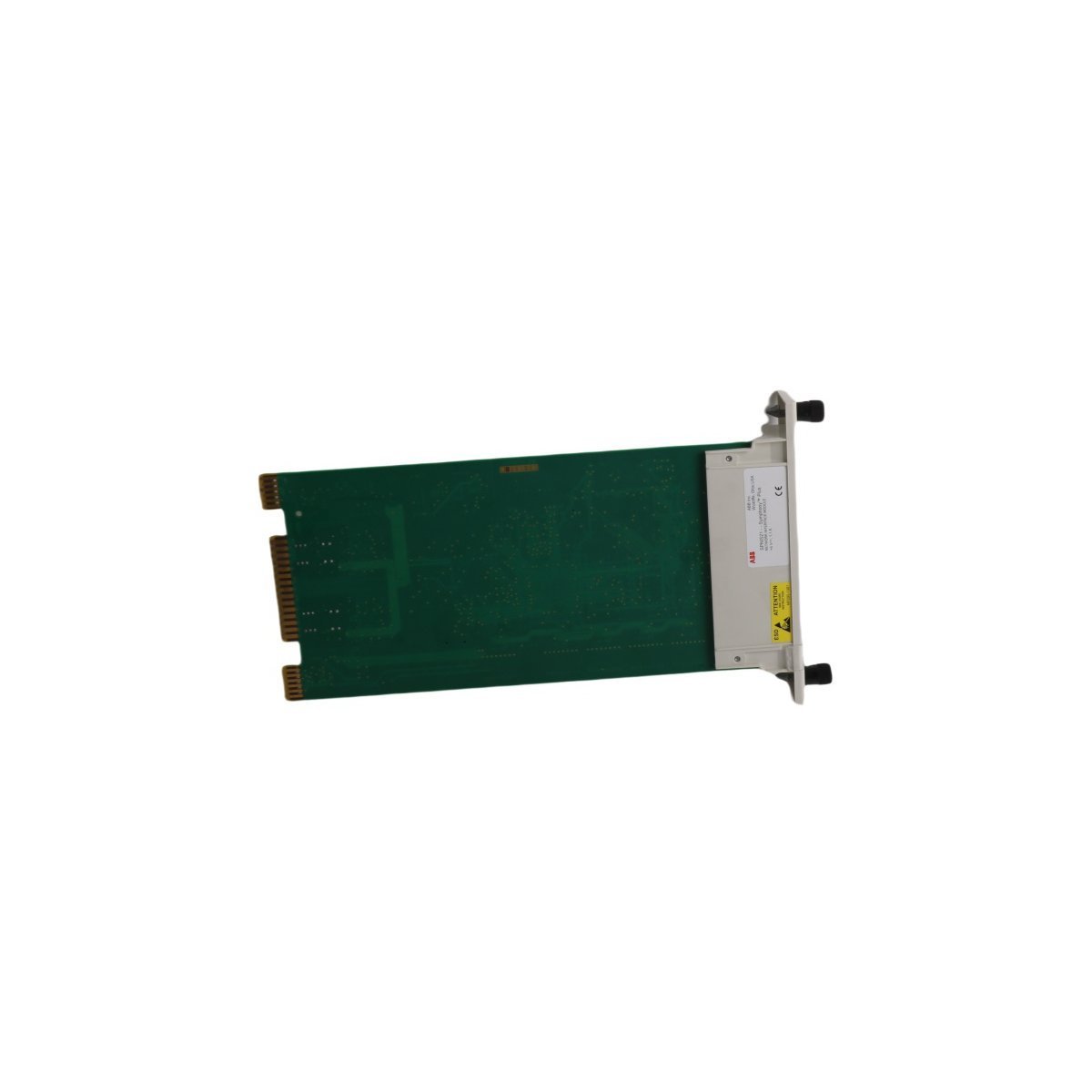
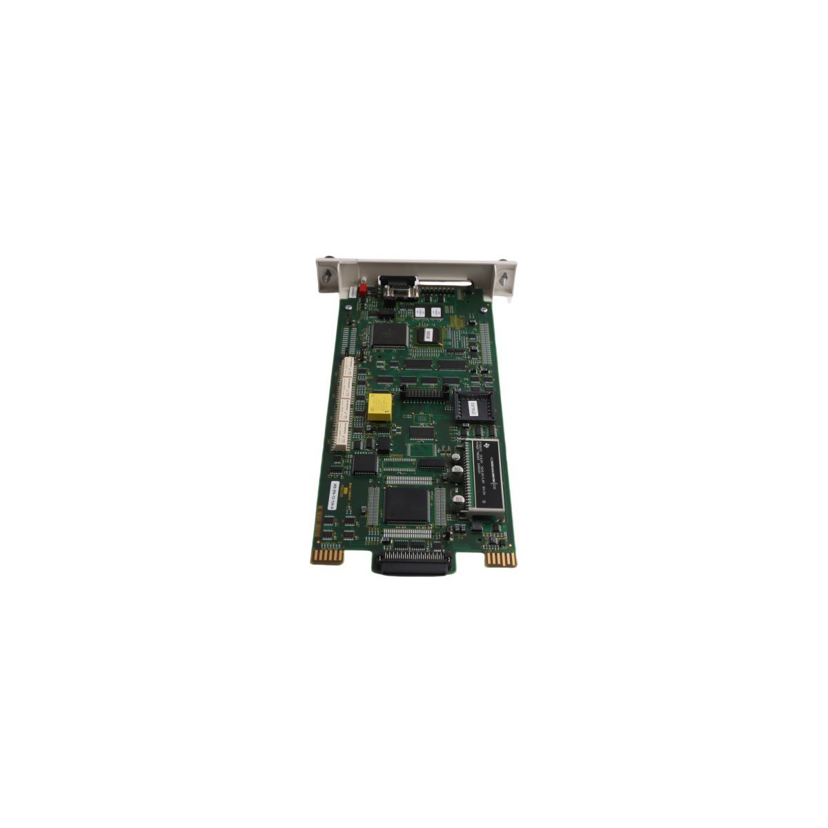
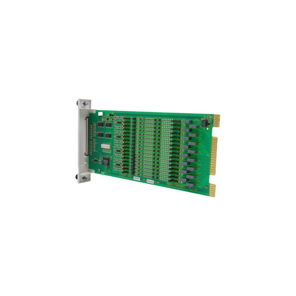
The ABB SPNIS21, also cataloged as the SPNIS21 Bailey Network Interface Module, operates as a dedicated hardware component for network connectivity and data exchange within Symphony Plus DCS platforms.
Hardware Specifications
Parameter
Specification
Model
SPNIS21
Brand
ABB
Origin
SWEDEN
Weight
0.24 kg
Dimensions
3.5 x 31.5 x 17.5 cm
Operating Temp
Standard Industrial Grade
Power Consumption
Not specified
Product Range
Symphony Plus
Deterministic Network Connectivity and Firmware
The integration of this module into the Symphony Plus environment relies on specific backplane bus communication protocols to ensure deterministic data exchange. Furthermore, users must verify firmware flash compatibility before initial deployment to ensure synchronization with the central controller’s scanning cycle. Consequently, the module manages I/O data throughput by maintaining high-speed signal polling, which is subsequently critical for maintaining scan time integrity across the distributed control network. In addition, strict adherence to these firmware requirements is necessary to prevent communication bottlenecks; moreover, this process is vital for preserving the overall deterministic nature of the I/O processing loop, thereby ensuring continuous and stable data synchronization.
Frequently Asked Questions (FAQ)
Q: Does the SPNIS21 support hot-swapping during system operation?
A: No, this module does not support hot-swapping. The backplane power must be isolated and the system de-energized before physical insertion or extraction to prevent electrical damage to the module interface and backplane pins.
Q: How can network-related communication latency be minimized?
A: Ensure that the network interface is correctly configured within the control loop parameters and that the communication cable shielding is properly terminated to the system earth to prevent electromagnetic interference.
Field Installation Guidelines
Physical Mounting: Install the module into the designated slot within the cabinet backplane. Ensure the retention screws or locking mechanisms are tightened to maintain structural stability.
Signal Shielding: All network and communication cabling must be shielded. Terminate shields to the designated common ground point at the cabinet entry to prevent ground loops.
Wiring Separation: Maintain clearance between communication interface cables and high-voltage power conduits to mitigate the risk of inductive noise coupling into the data stream.
Visual Inspection: Before finalizing installation, inspect all pins on the module and backplane for oxidation or mechanical deformation.
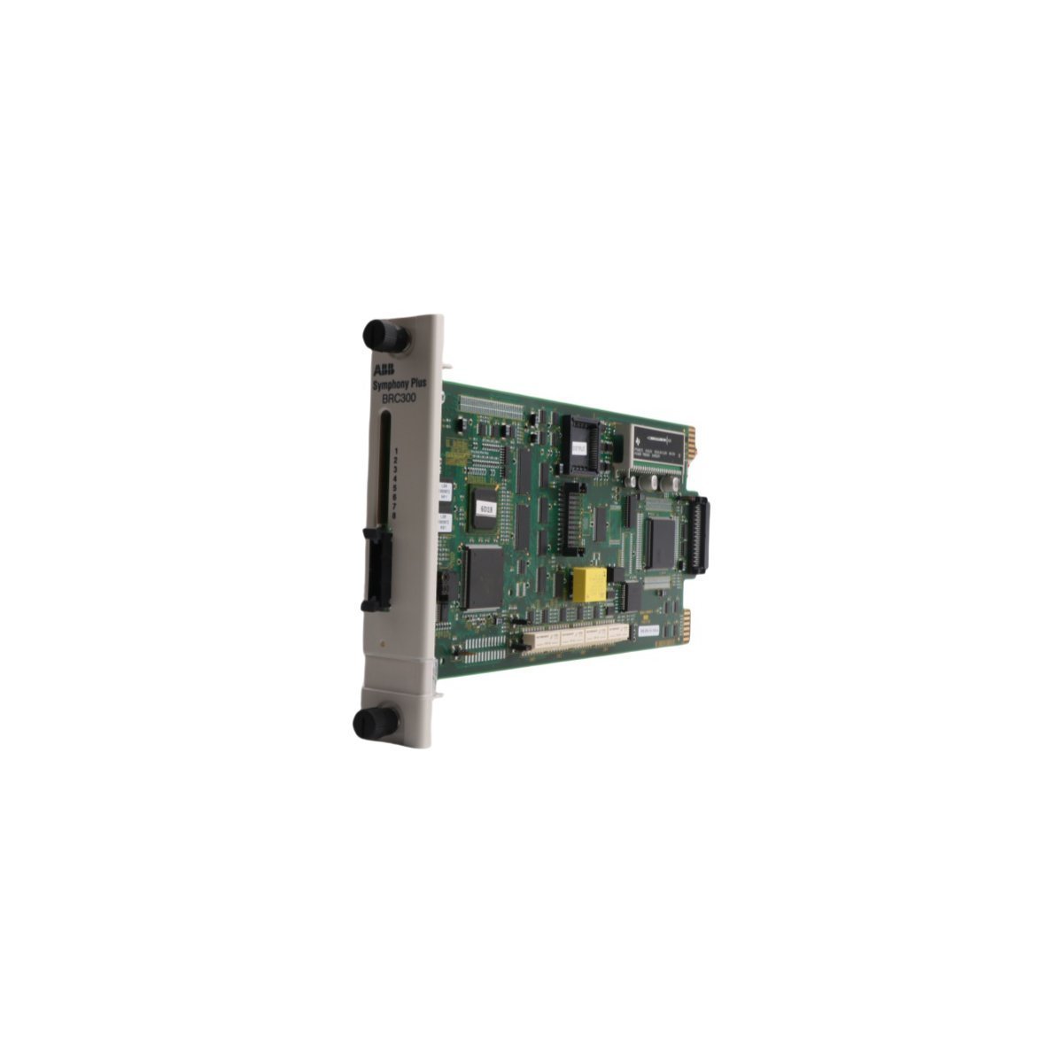
The ABB SPBRC300 is a high-performance central bridge controller for Symphony Plus DCS. Featuring 16 digital inputs, 8 digital outputs, and dual Ethernet/Modbus support, this Swedish-engineered unit provides reliable, real-time logic execution and seamless network integration for demanding industrial automation.
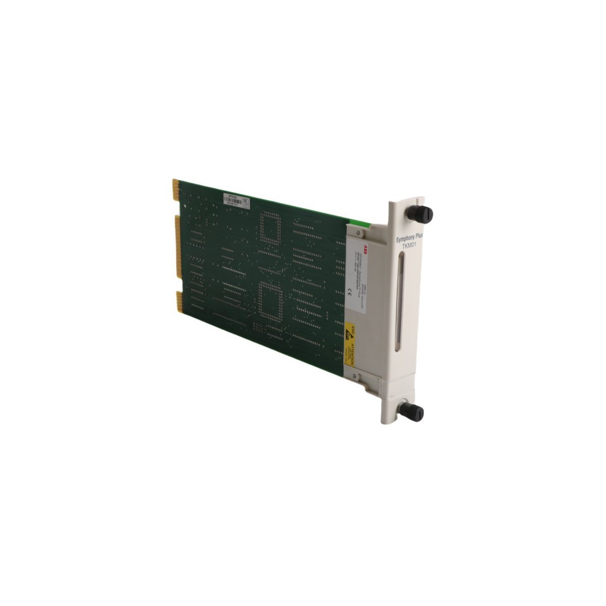
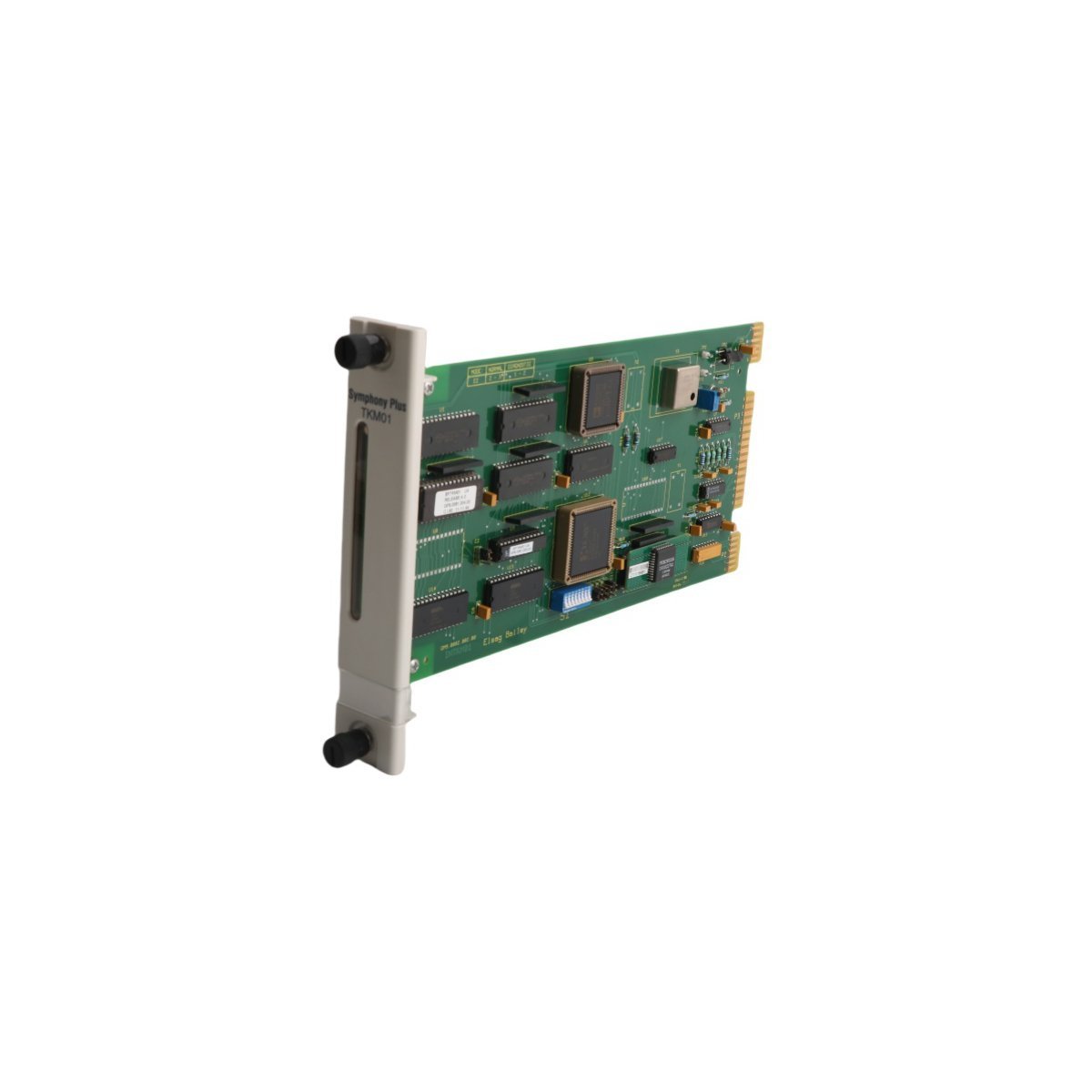
The ABB SPTKM01 is a Symphony Plus SOE Time Keeper Master designed for high-resolution event timestamping and synchronization. This rugged DCS module features non-volatile flash memory and a wide operating temperature range, providing essential diagnostic data for complex industrial automation systems.
The Allen-Bradley 1761-NET-AIC is a versatile AIC+ communication adaptor that connects DF1 devices to DH-485 networks. It provides RS-232 to RS-485 isolation and supports MicroLogix and SLC 500 controllers for robust industrial data exchange.
The ABB SPASI23 is a high-performance analog input module for Symphony Plus DCS environments.It delivers precise signal conversion, robust electrical isolation, and seamless backplane integration for reliable industrial process monitoring and control.
The ABB SPSED01 is a 16-channel Sequence of Events (SOE) digital input module for Symphony Plus systems. Weighing 0.36kg, this Swedish-engineered component provides millisecond-accurate event recording and robust diagnostic features. It ensures reliable data acquisition for complex industrial process monitoring and fault analysis.
The ABB SPDSI14 is a 16-channel, 48 Vdc digital input module for Symphony Plus and Bailey Infi 90 systems. Weighing 0.2kg, this Swedish-made module offers high-density signal acquisition, dielectric-grade housing, and full CE/UL compliance for reliable industrial DCS performance.
The GE DS200SLCCG1ACC is a high-speed LAN communications card for Mark V Speedtronic systems. This genuine General Electric module manages critical data exchange for turbine controls and digital drives. It features a compact USA-made design, 0.24 kg weight, and advanced signal processing capabilities for robust industrial network integration.
The Allen-Bradley 1756-CNBR is a redundant ControlNet bridge module for ControlLogix systems. It provides 5 Mbps deterministic communication and dual BNC ports for media redundancy. This module supports up to 64 connections and 99 nodes in mission-critical automation environments.
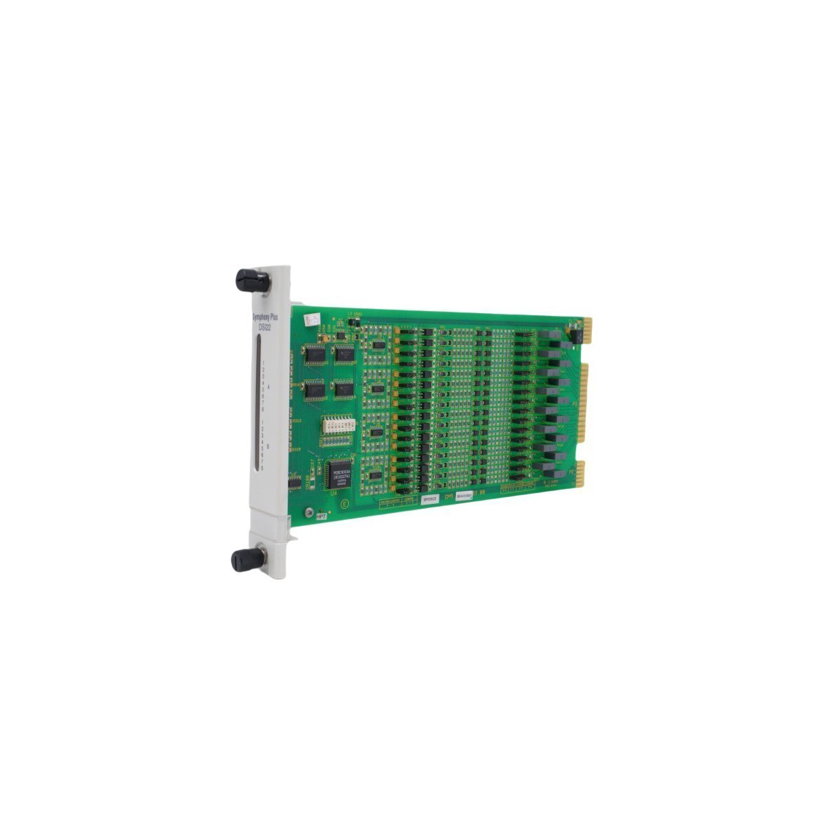
The ABB SPDSI22 is a 16-channel universal digital input module for Symphony Plus and INFI 90 systems. It features 32 jumpers for flexible configuration and isolated signal processing for robust DCS monitoring.
The Allen-Bradley 1785-BEM is a PLC-5 Backup Communication Expansion Module. It provides high-speed redundancy for DH+ and Remote I/O networks with 1.2 MBaud transfer rates. This 1771-chassis module ensures continuous data synchronization for mission-critical automation systems.
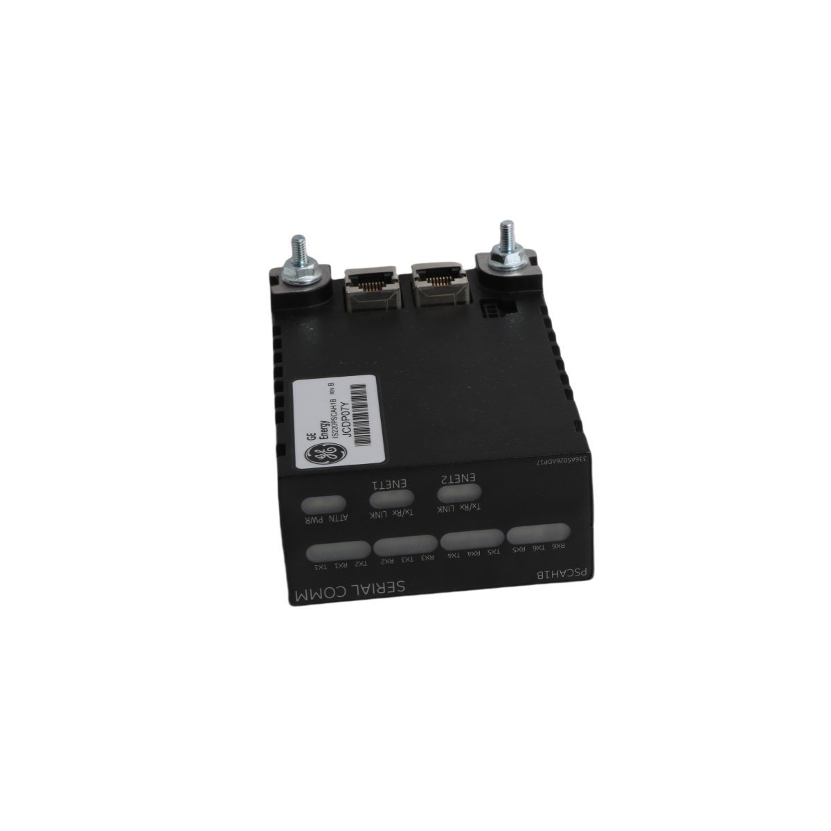
The GE IS220PSCAH1A is a Serial Modbus Interface Pack for Mark VIe systems. It supports RS-232/422/485 protocols, dual Ethernet redundancy, and RTU Master services.
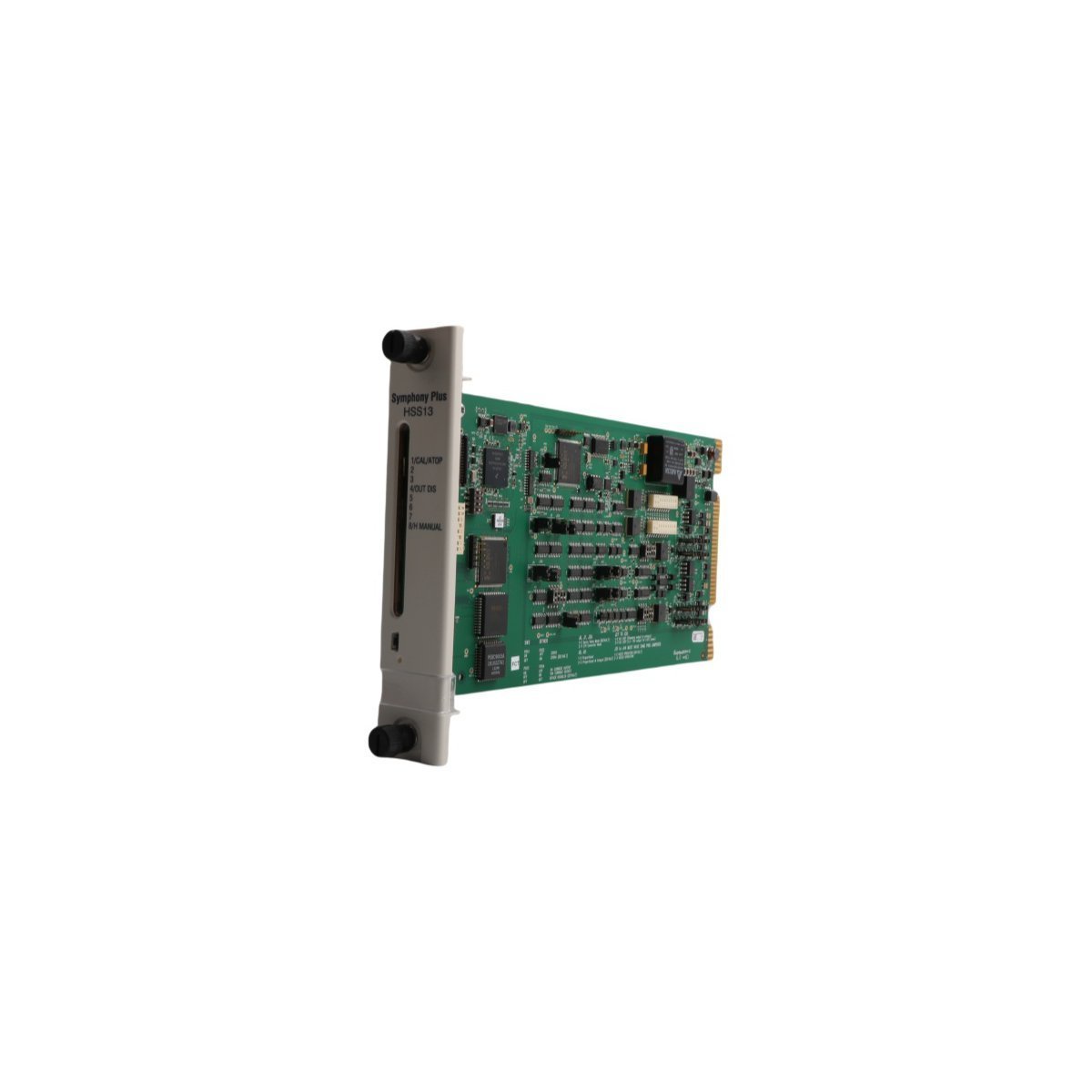
The ABB SPHSS13 is a high-performance 50 kHz Hydraulic Servo Module for the Symphony Plus DCS.It offers precision control for turbine valves and hydraulic actuators, featuring advanced diagnostics and a compact, rack-mounted design for demanding industrial motion control.
We are committed to protecting your privacy. The information collected here is strictly used to provide the requested quotes, technical support, and relevant industrial automation solutions.