Sale!
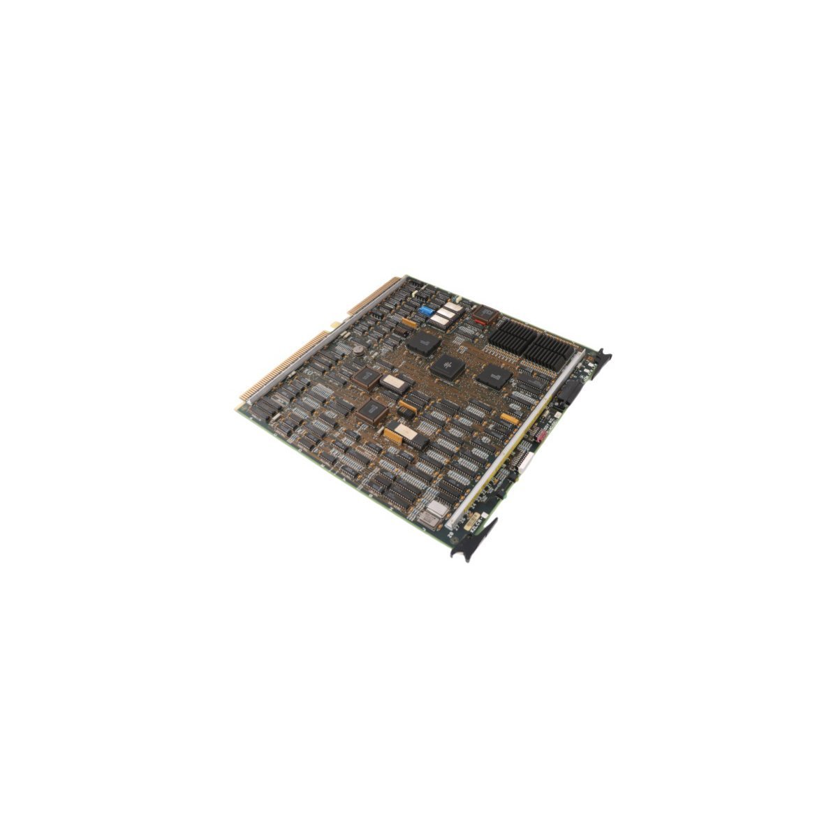
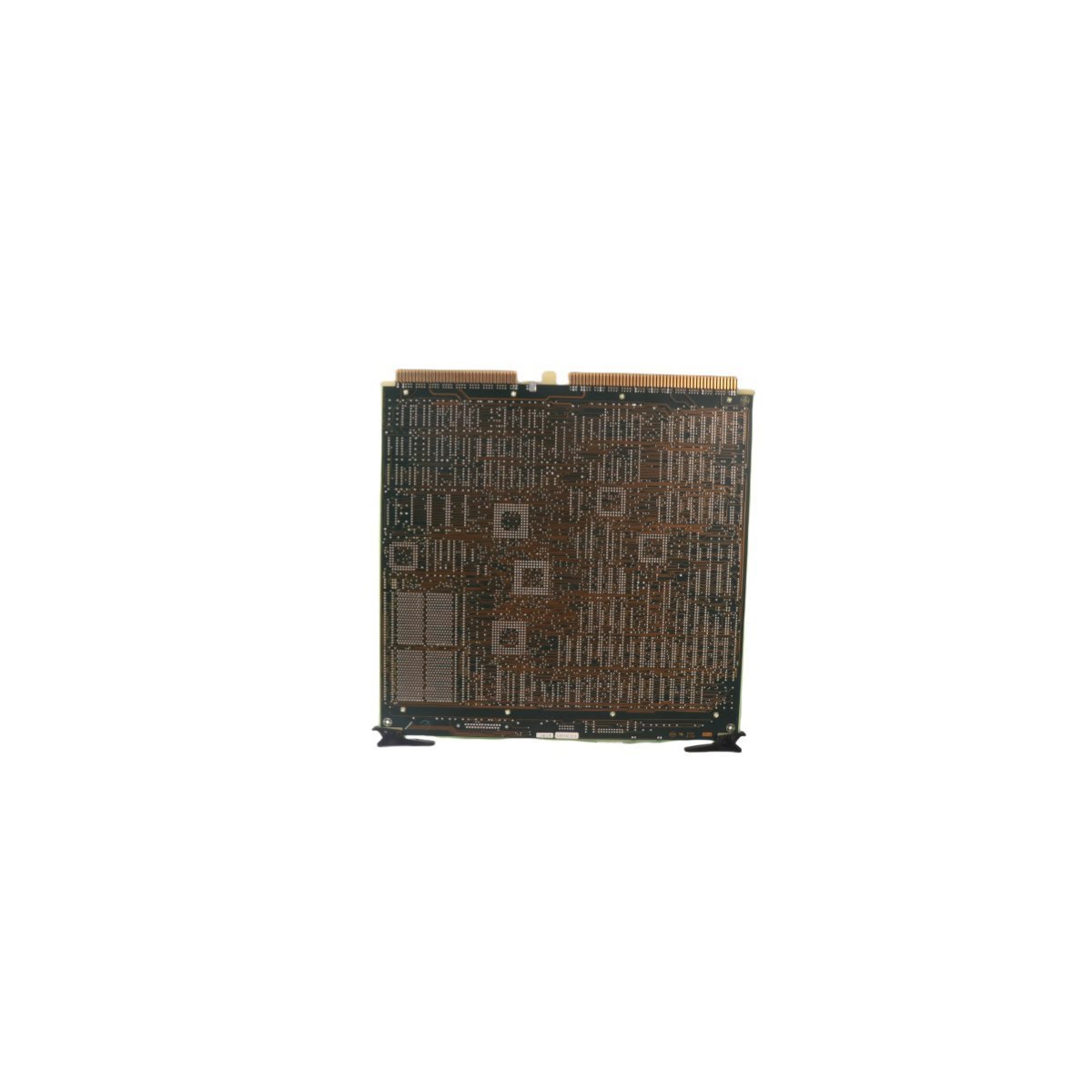
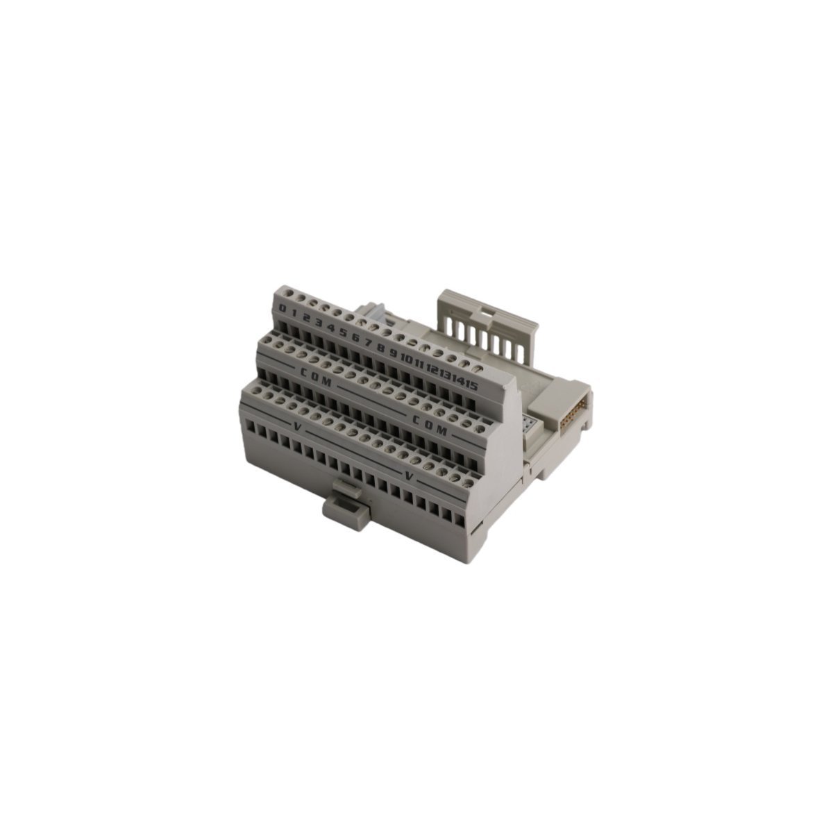
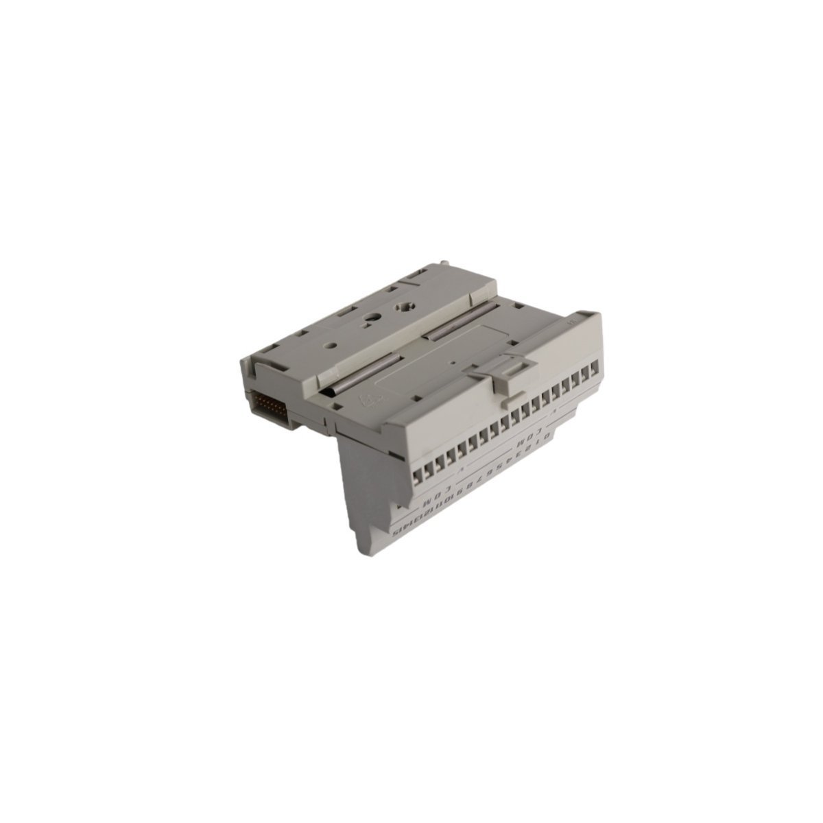
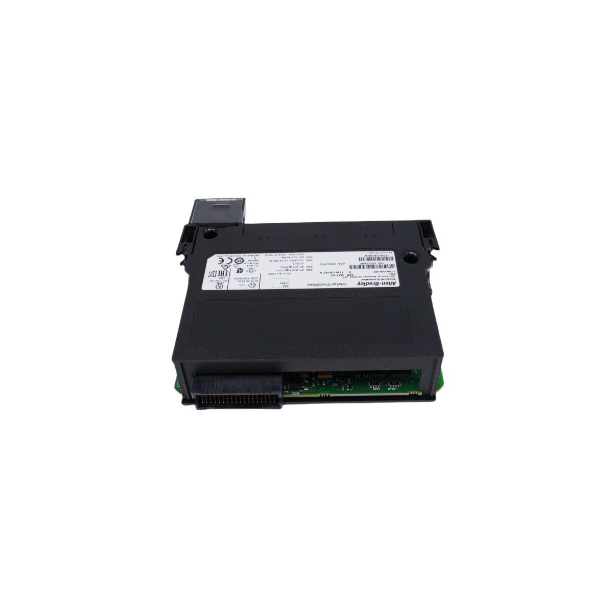
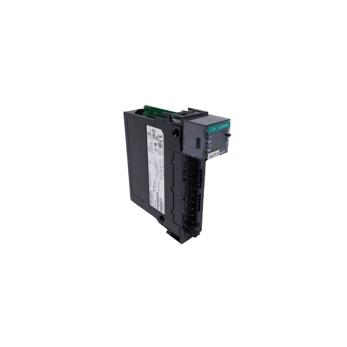
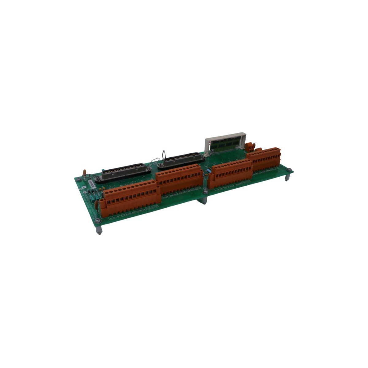
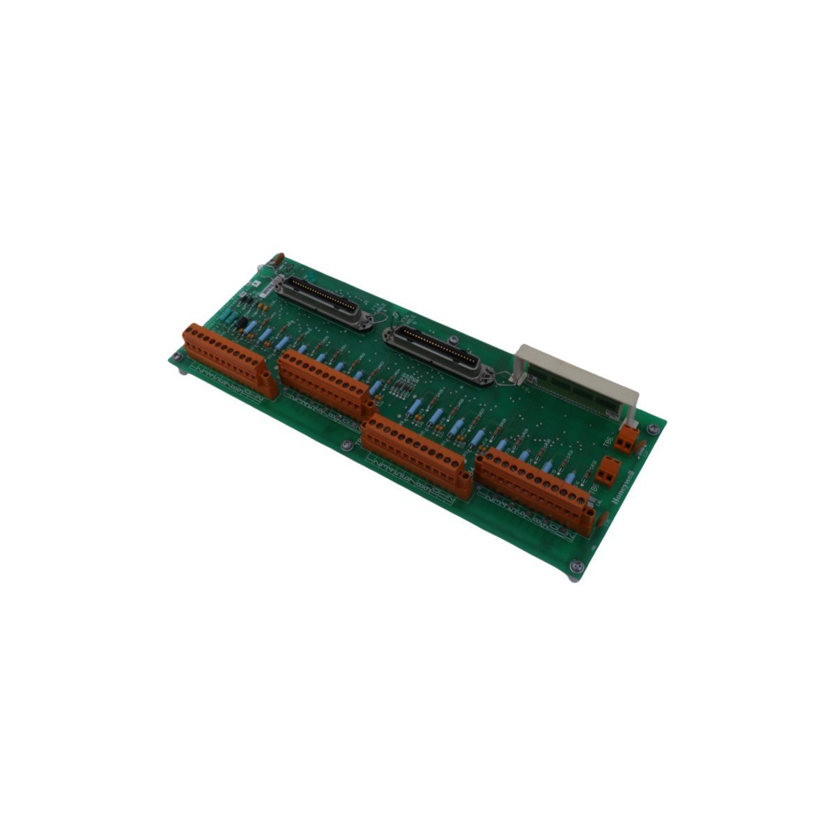
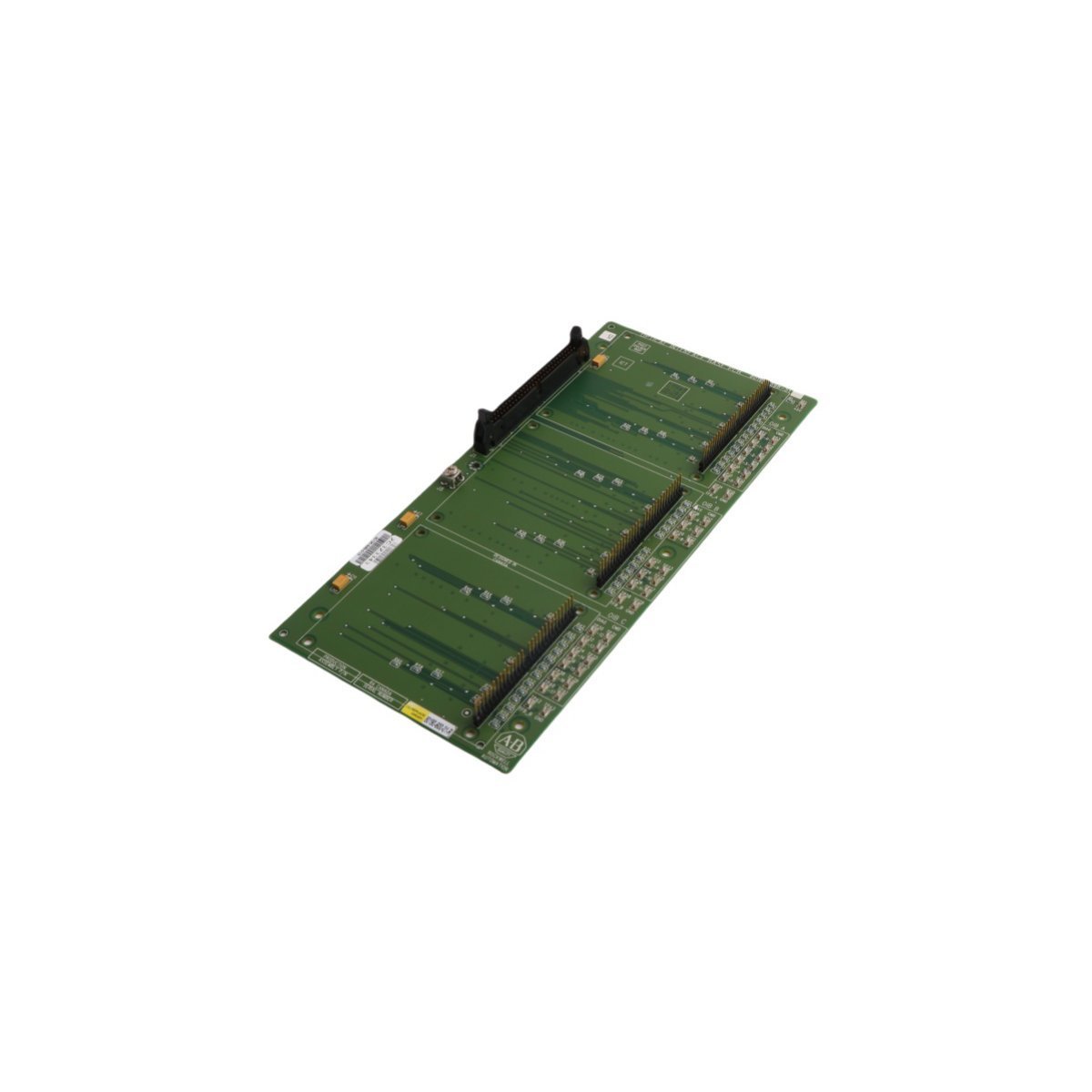
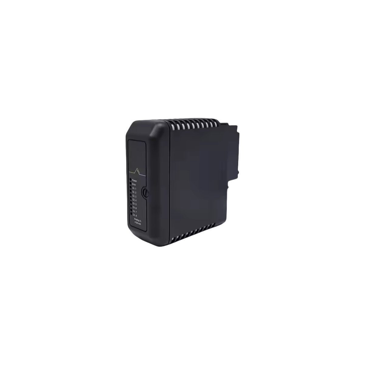
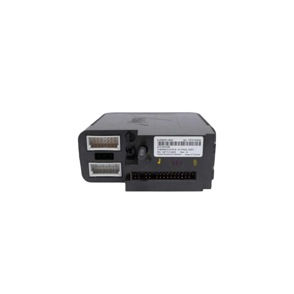
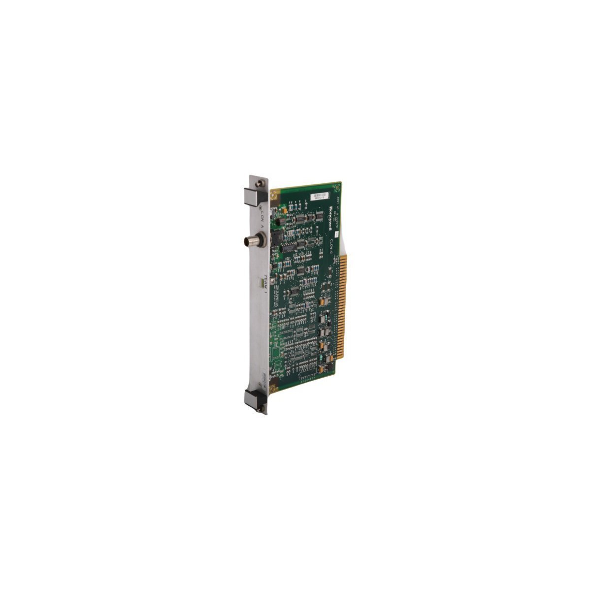
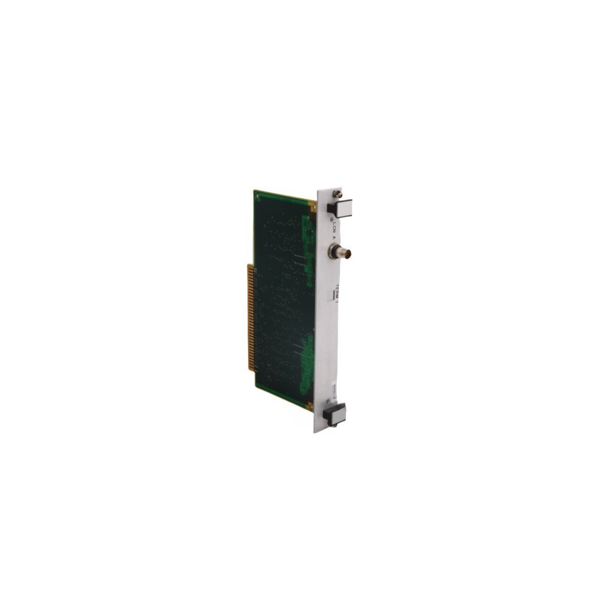
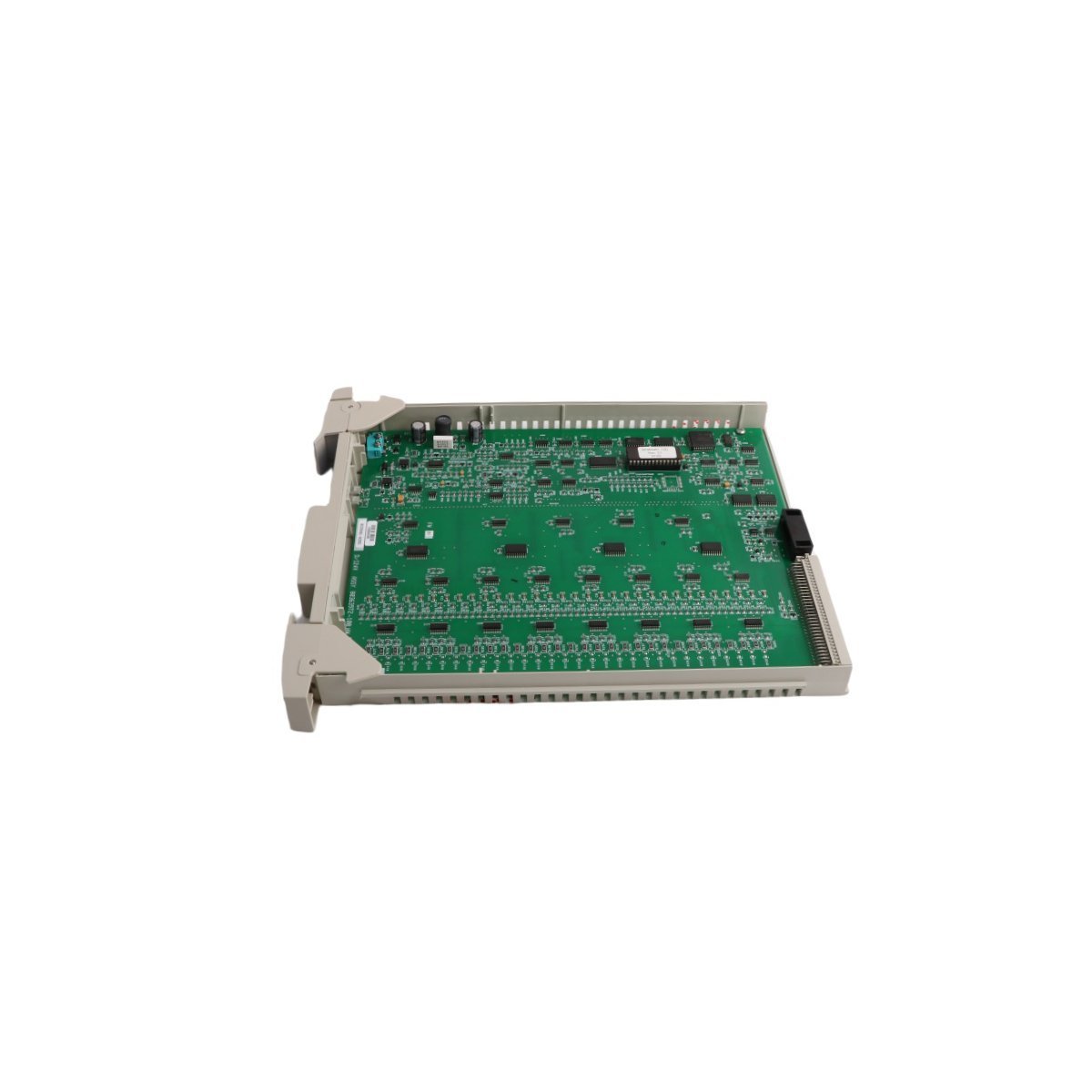
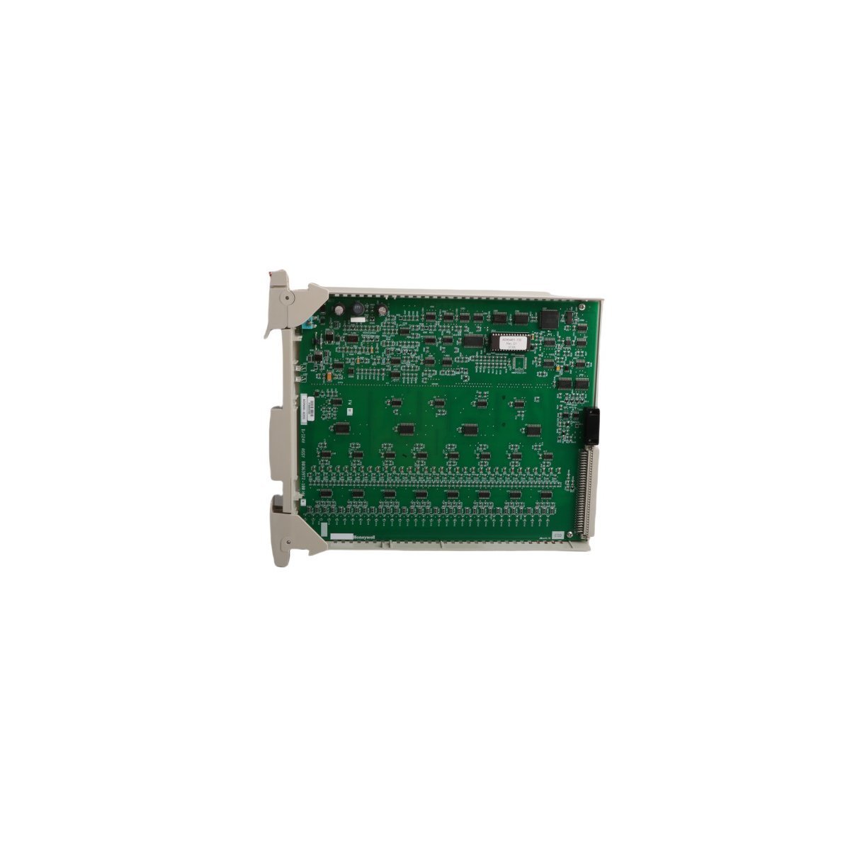
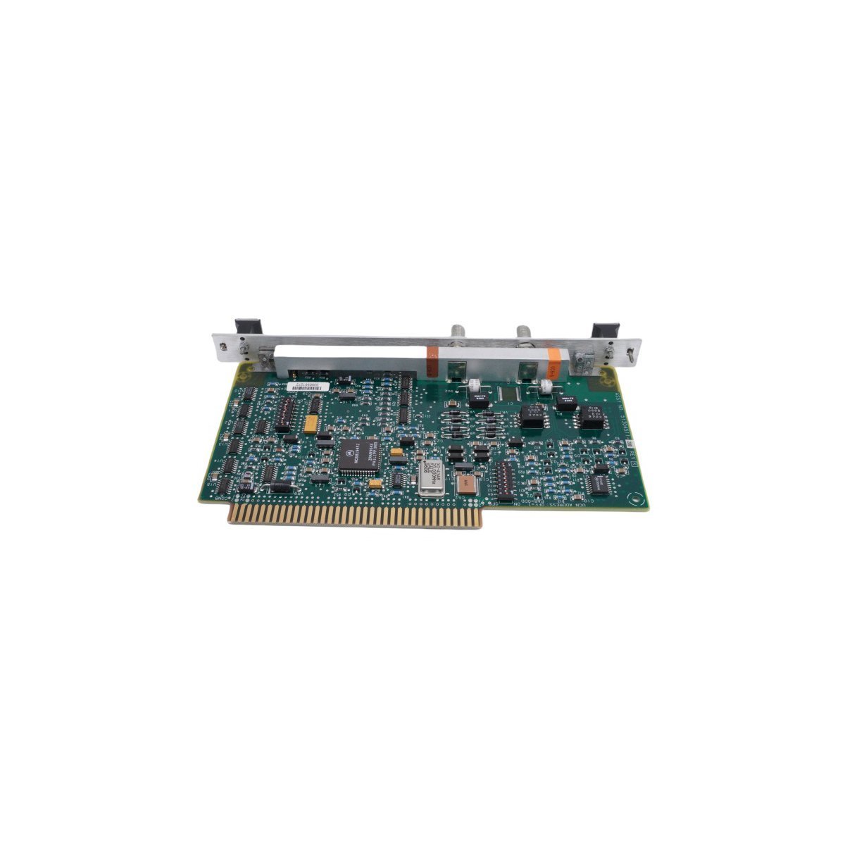
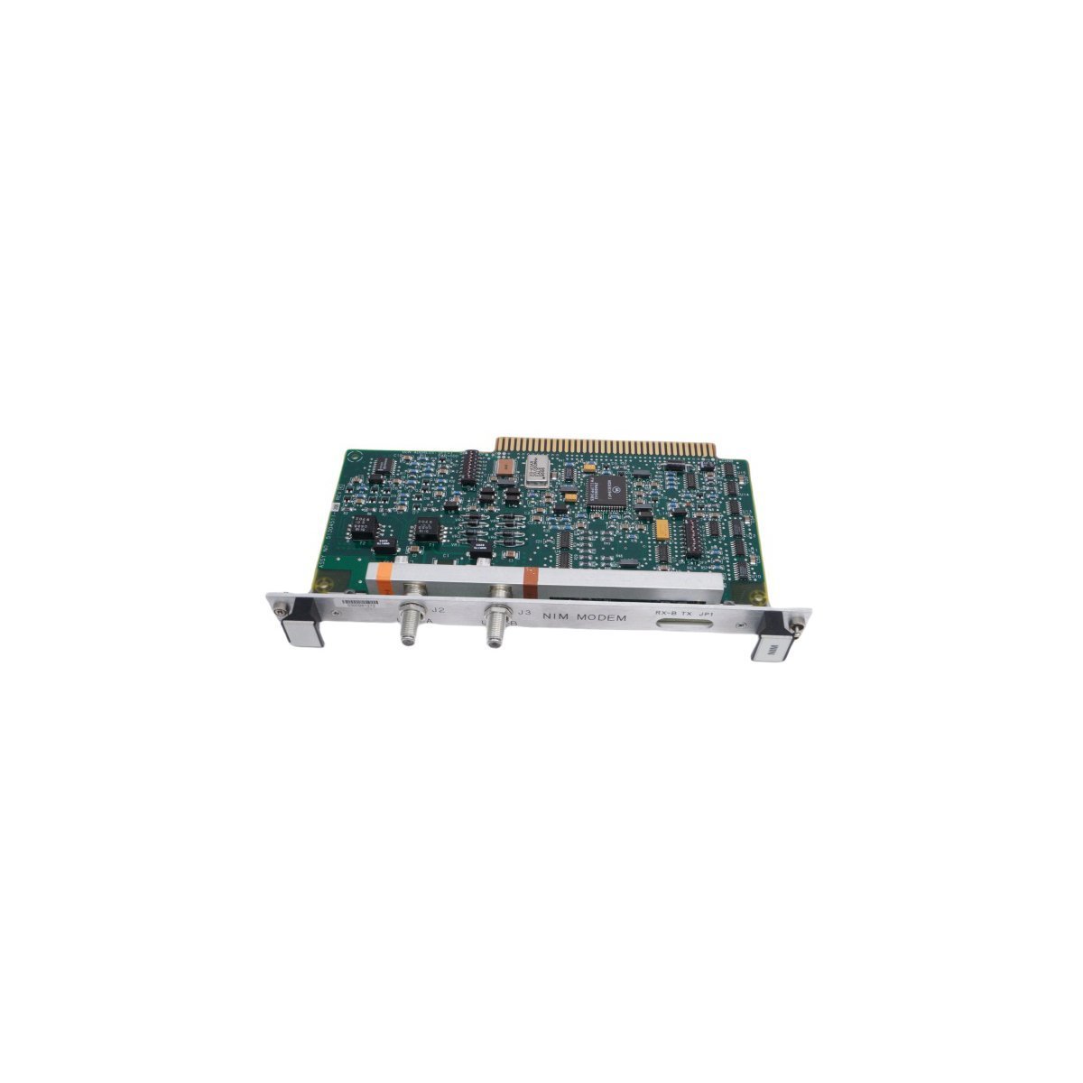
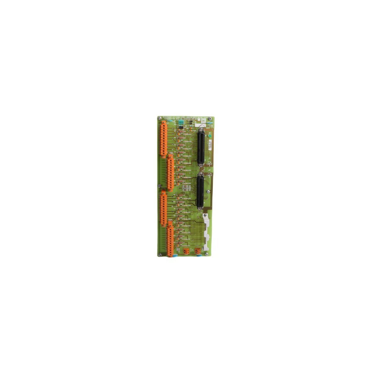
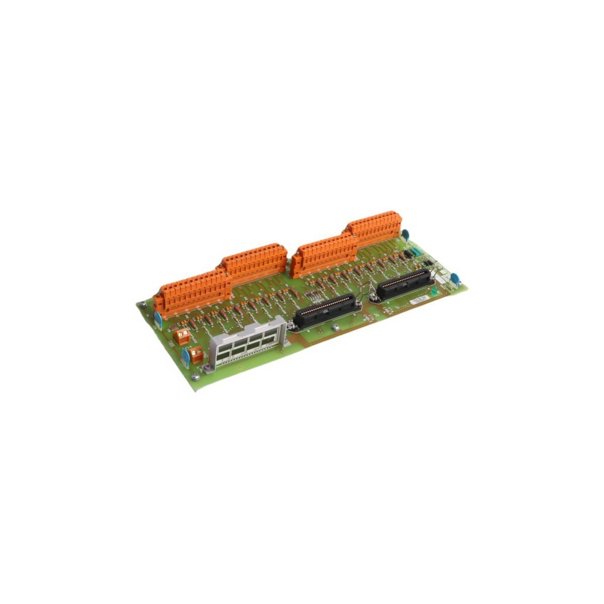
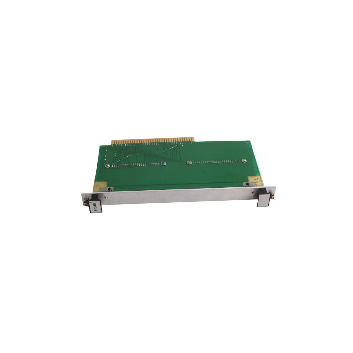
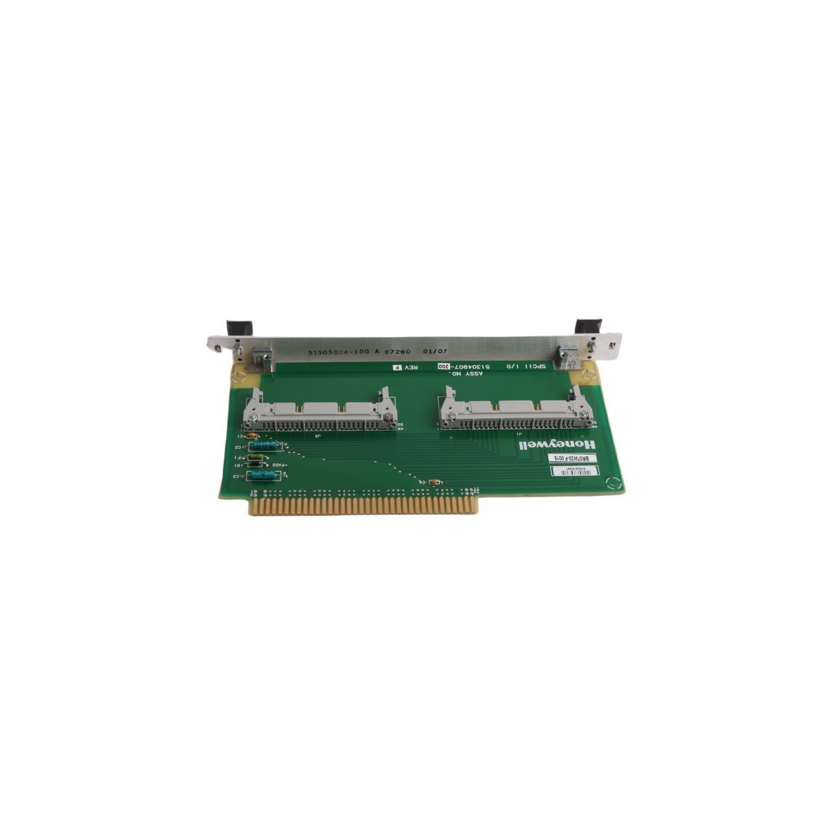
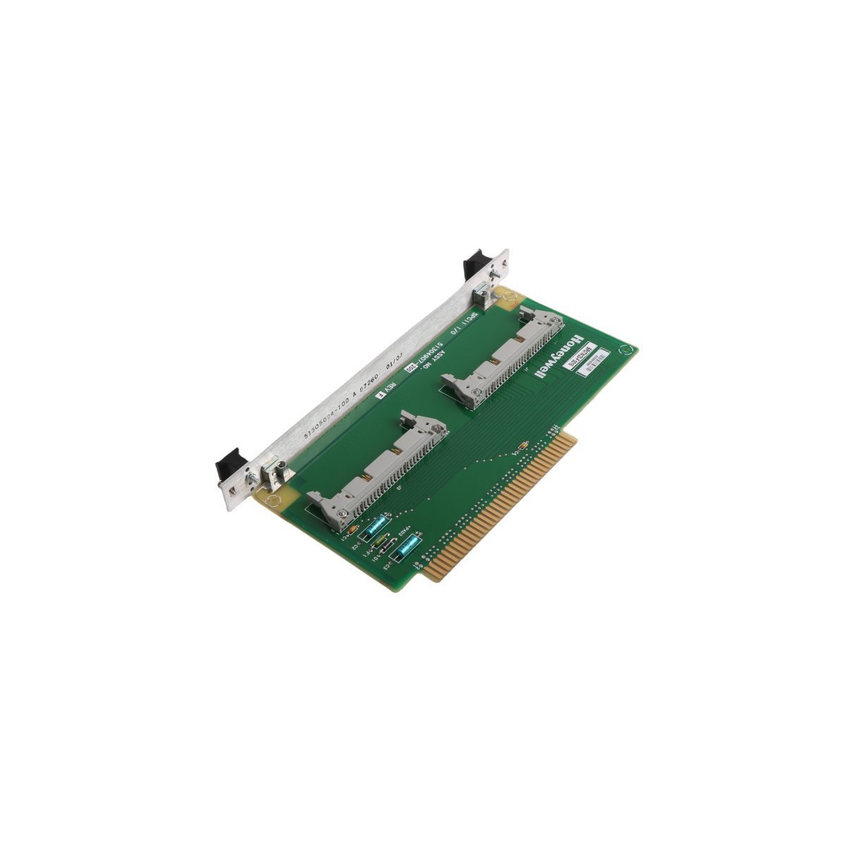
Honeywell K2LCN-8 51401551-801 Local Control Network Module
The Honeywell K2LCN-8 51401551-801, also cataloged as the K2LCN-8 51401551-801 Local Control Network Module, operates as a dedicated hardware component for local control network routing and distributed communications within TDC 3000 platforms.
Hardware Specifications
| Parameter | Specification |
|---|---|
| Model | K2LCN-8 51401551-801 |
| Brand | Honeywell |
| Origin | USA |
| Weight | 1 kg |
| Dimensions | 36.6 x 36.3 x 2 cm |
| Operating Temp | -20 deg C to 70 deg C |
| Power Consumption | 24 VDC nominal |
| Module Type | Local Control Network Module |
| Range of Product | TDC 3000 |
| System | DCS |
| Communication Service | Ethernet router |
| Status | Active |
Process Control and Signal Isolation Architecture
The module manages loop-level data transmissions utilizing 4-20 mA HART loop protocol frameworks to maintain high signal fidelity across distributed automation nodes. Dedicated channel-to-channel isolation prevents ground loops and eliminates electromagnetic interference within complex industrial enclosures. Additionally, built-in cold junction compensation (CJC) maintains thermocouple accuracy, while integrated network architecture ensures deterministic execution and reliable packet routing.Frequently Asked Questions
Q: What precautions should be taken regarding backplane current consumption when installing multiple K2LCN-8 51401551-801 modules?A: System engineers must verify that the total cumulative current draw on the node power supply does not exceed the maximum specified wattage and amperage output limits of the chassis backplane.Q: Can the K2LCN-8 51401551-801 module be hot-swapped while the system is powered on?A: Hot-swapping is restricted unless specific redundancy switchover procedures and fail-safe states are active to prevent interruption of real-time control loops.Field Installation Guidelines
- Secure the hardware module firmly within the specified chassis slot, ensuring proper pin alignment to prevent backplane damage.
- Route all communication and signal cabling away from high-voltage power lines to minimize electrical noise coupling.
- Ensure proper system grounding by connecting all chassis earth terminals to the central control room grounding bus.