Sale!
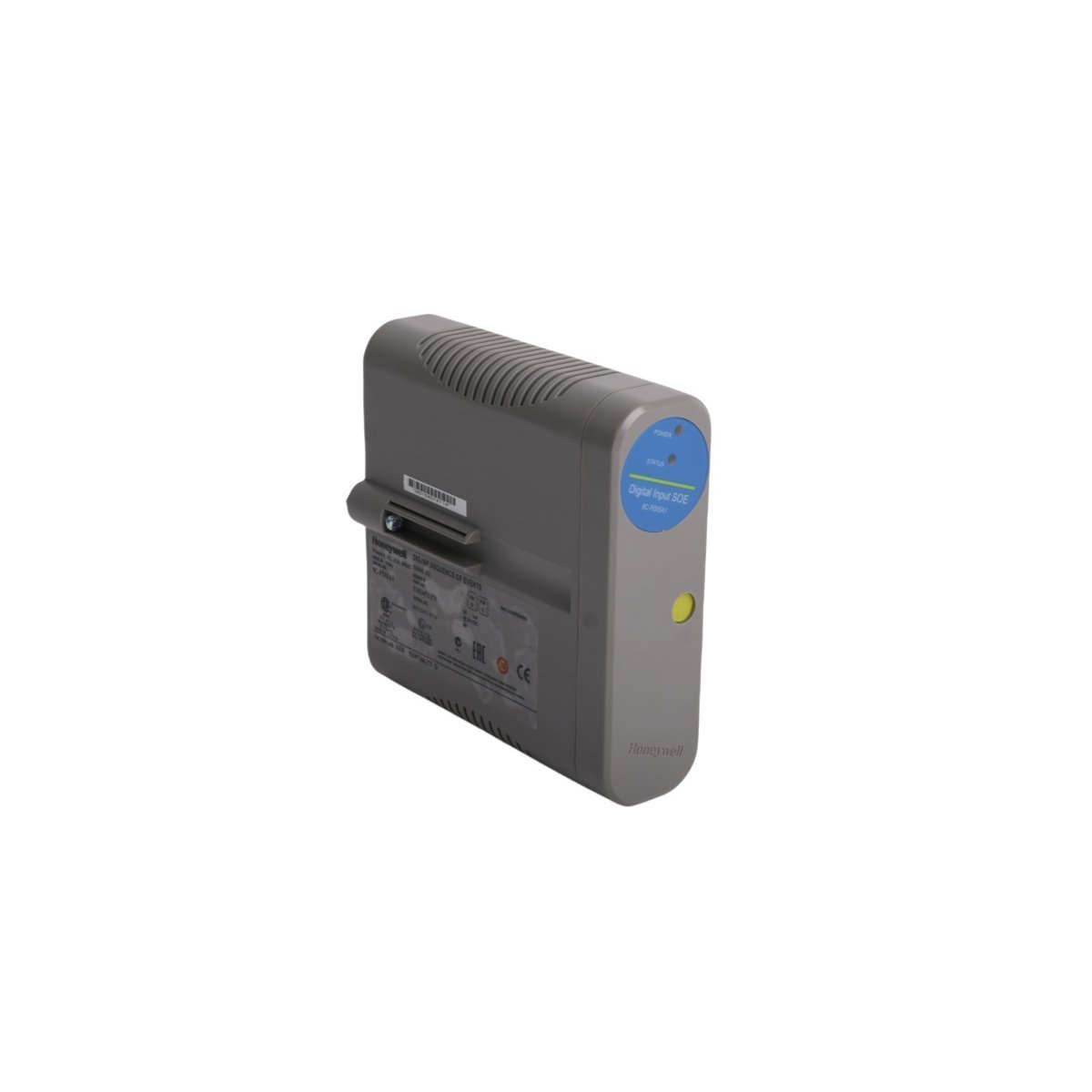
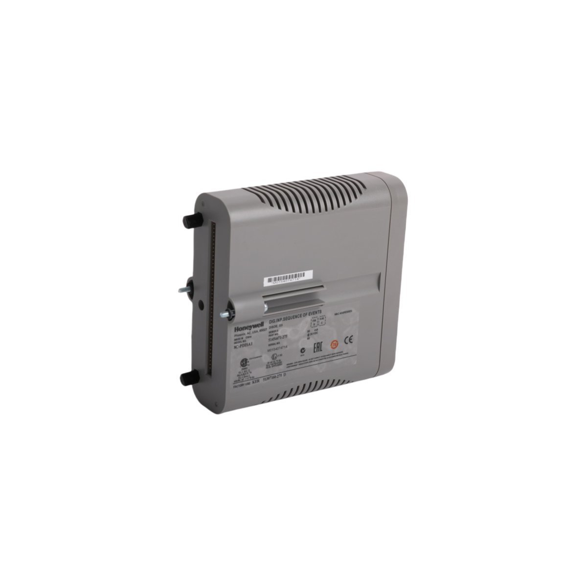
Honeywell 8C-PDISA1 Digital Input Sequence of Events Module
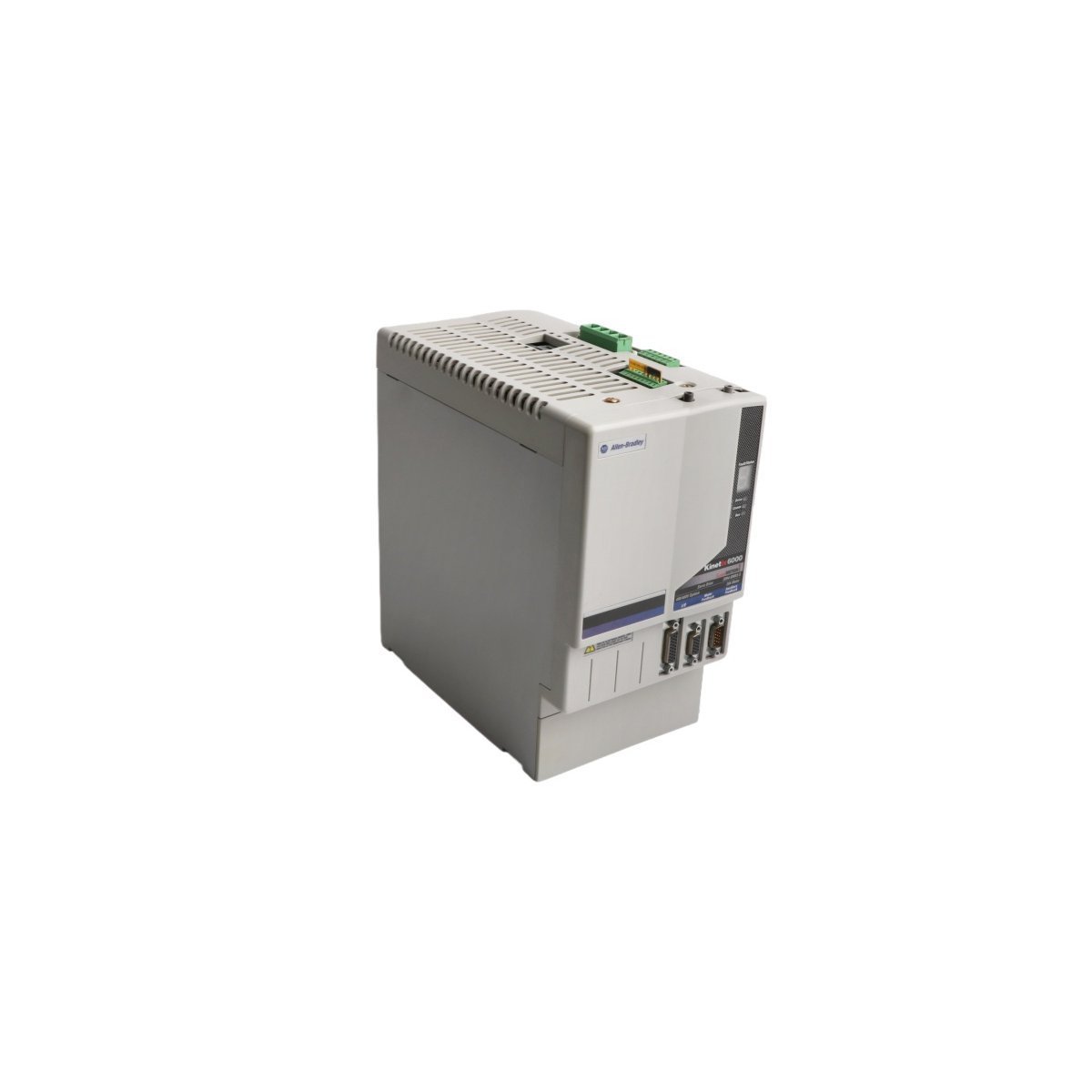
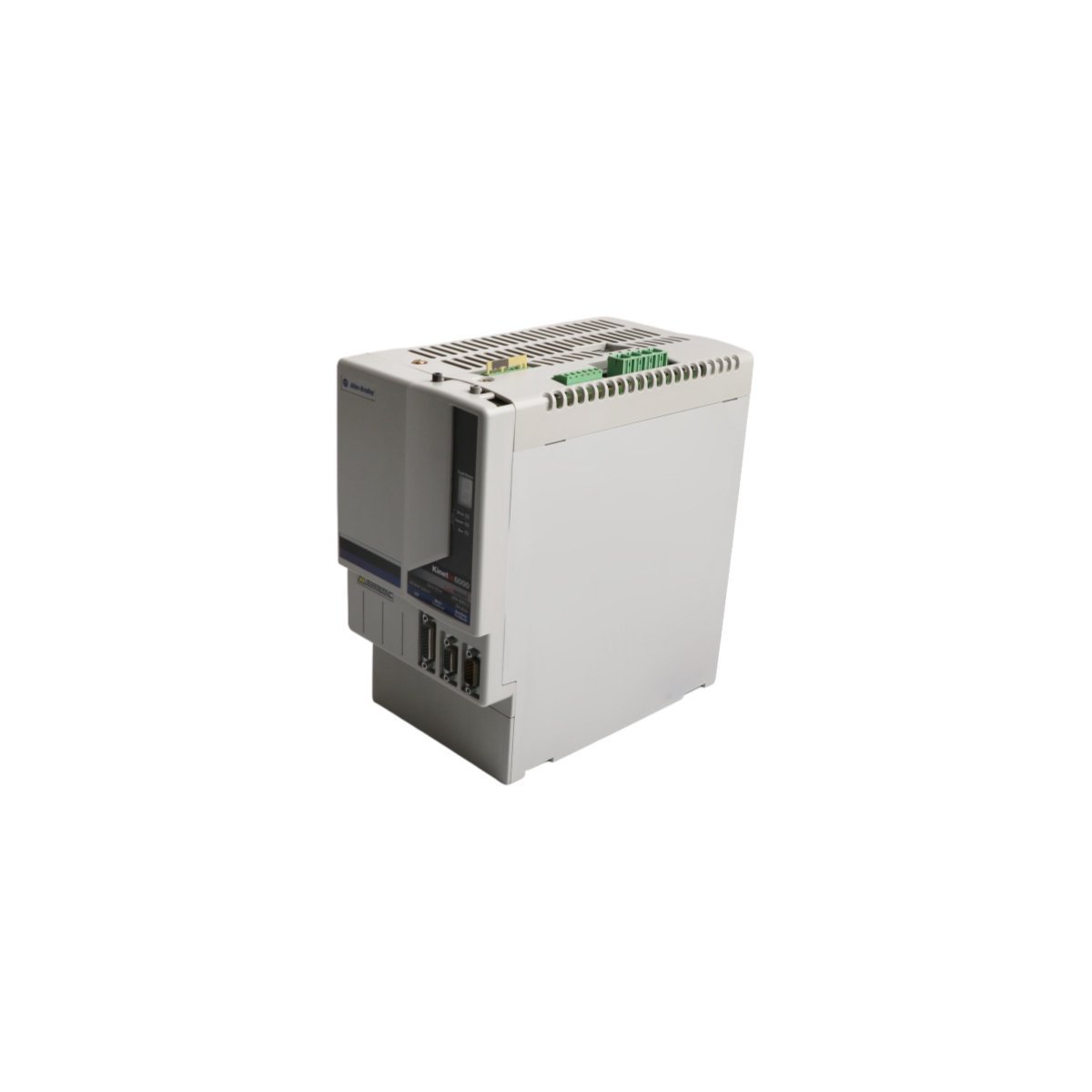
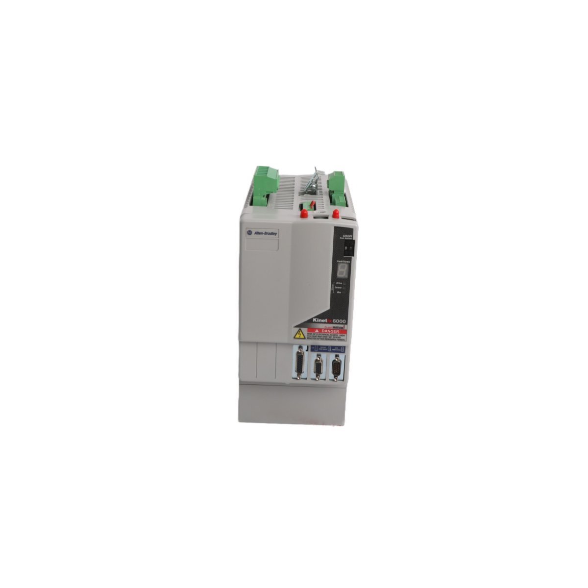
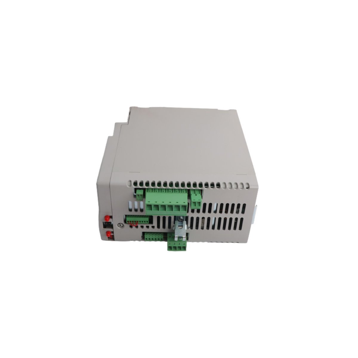
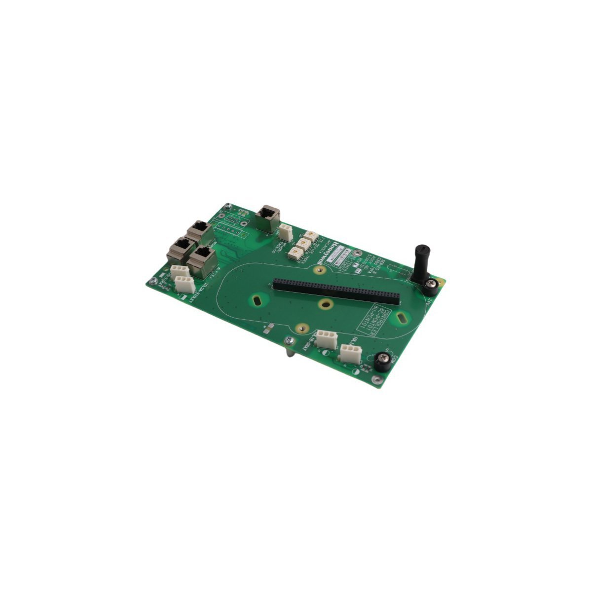
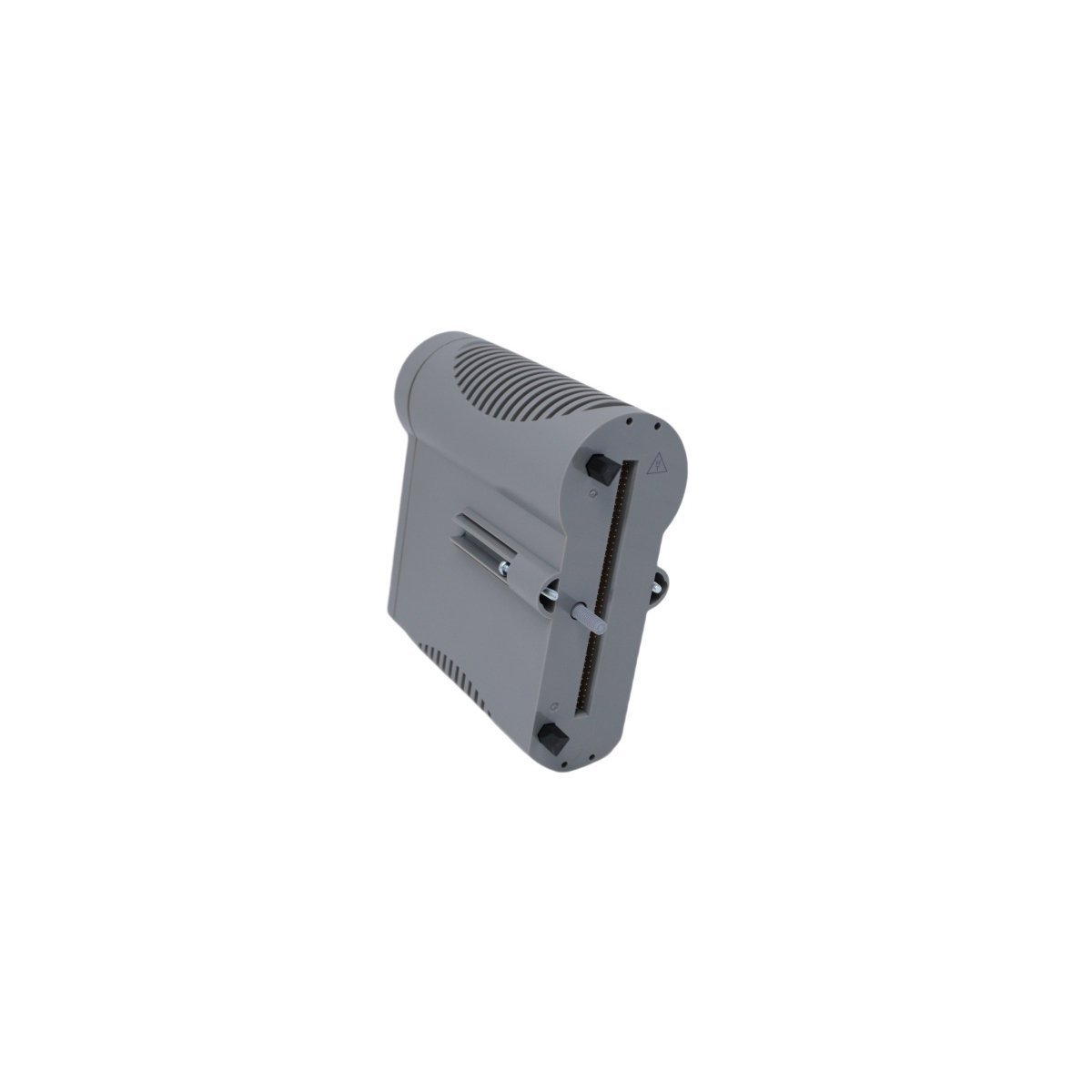
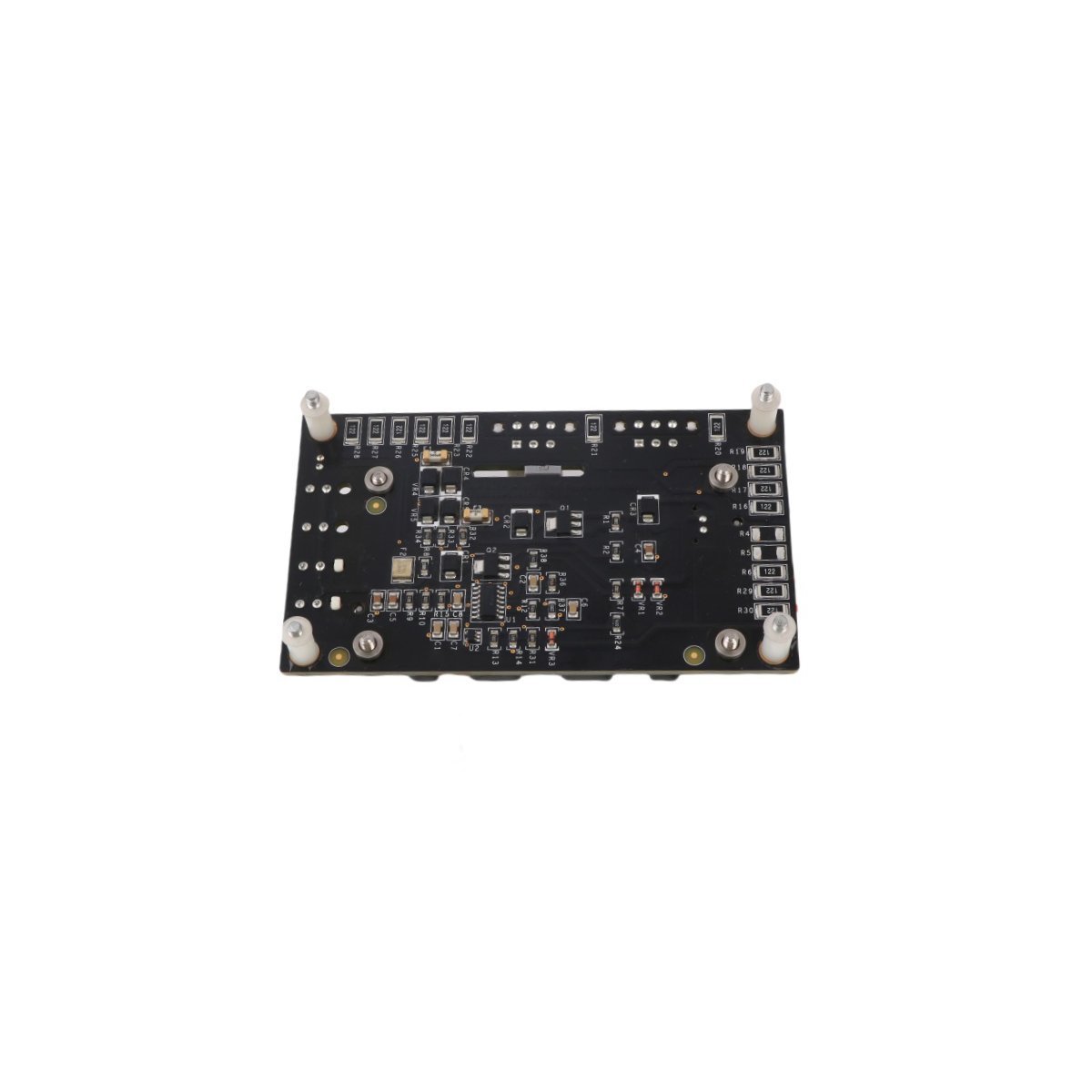
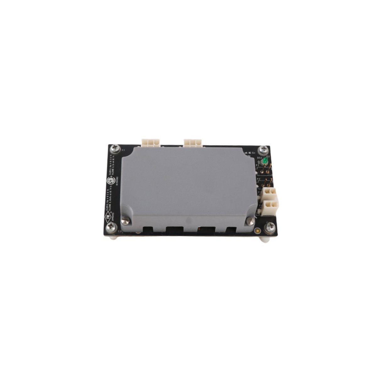
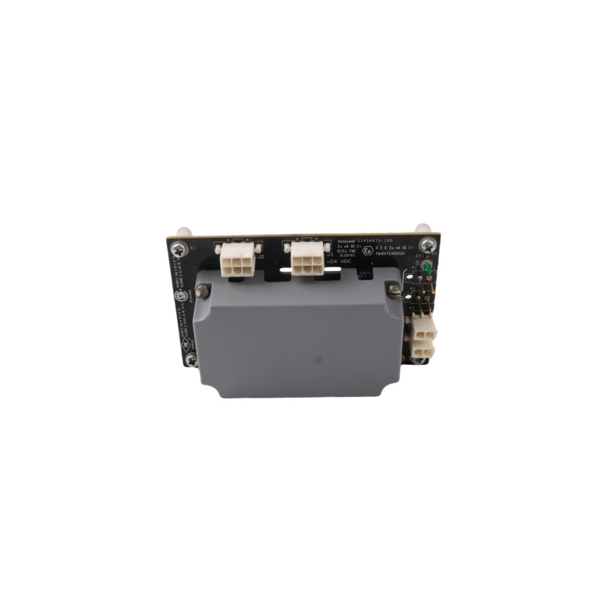
The Honeywell 8C-PDISA1 51454471-275, also cataloged as the 8C-PDISA1 51454471-275 Digital Input Sequence of Events Module, operates as a dedicated hardware component for high-speed signal timestamping and state change detection within Experion PKS platforms.
Hardware Specifications
| Parameter | Specification |
|---|---|
| Model | 8C-PDISA1 51454471-275 |
| Brand | Honeywell |
| Origin | USA |
| Weight | 0.3 kg |
| Dimensions | 6 cm x 15.2 cm x 14.3 cm |
| Operating Temp | Industrial standard |
| Power Consumption | Series 8 backplane load |
| Module Type | Digital Input Sequence of Events (SOE) |
Process Instrumentation and Connectivity
In process control architectures, the 8C-PDISA1 provides the physical interface for discrete signal monitoring. To begin with, the module configuration allows for precise Sequence of Events (SOE) recording, which is, inherently, necessary for post-event analysis. Furthermore, the design incorporates channel-to-channel isolation; consequently, this isolation effectively protects the logic processing circuitry from common-mode transients. Moreover, the input circuitry is engineered to support 4-20 mA HART loop protocol compatibility in associated analog loops, thus maintaining signal integrity across the I/O bus. Additionally, when considering operational stability, the module utilizes internal cold junction compensation (CJC) logic where applicable to ensure accuracy. Finally, the integration with the Experion PKS control network facilitates high-speed data transfer between field sensors and the central processor, thereby ensuring that state changes are registered with sub-millisecond resolution.Frequently Asked Questions
Q: Does the 8C-PDISA1 support hot-swapping during active process operations?A: Yes, the Series 8 architecture permits the hot-swapping of the module; however, ensure the removal and insertion procedures follow the standard safety protocols to avoid inducing signal transients on the backplane.Q: What is the primary function of the Sequence of Events (SOE) capability in this module?A: The SOE functionality allows the system to timestamp digital input transitions with high temporal precision, which is necessary for reconstructing the sequence of alarms and trips during operational disturbances.Field Installation Guidelines
- Mounting: Secure the module onto the Series 8 I/O mounting tray. Verify that the I/O termination assembly (IOTA) is correctly aligned with the module pins before applying pressure to engage the connector.
- Shielding: Terminate the cable shields at the dedicated earth bar on the IOTA to maintain electromagnetic compatibility (EMC) and minimize noise injection into the input channels.
- Wiring: Maintain strict segregation between signal-level wiring and high-voltage AC or DC power lines. Use twisted-pair shielded cables for all field inputs to prevent crosstalk and interference.
- Grounding: Confirm that the system ground bus is free from significant potential differences to prevent ground loops, which can result in erroneous digital state registration.