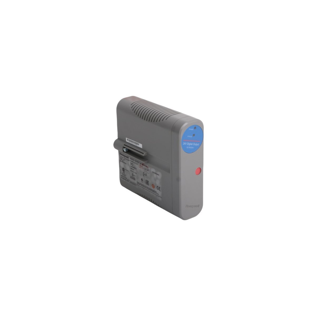
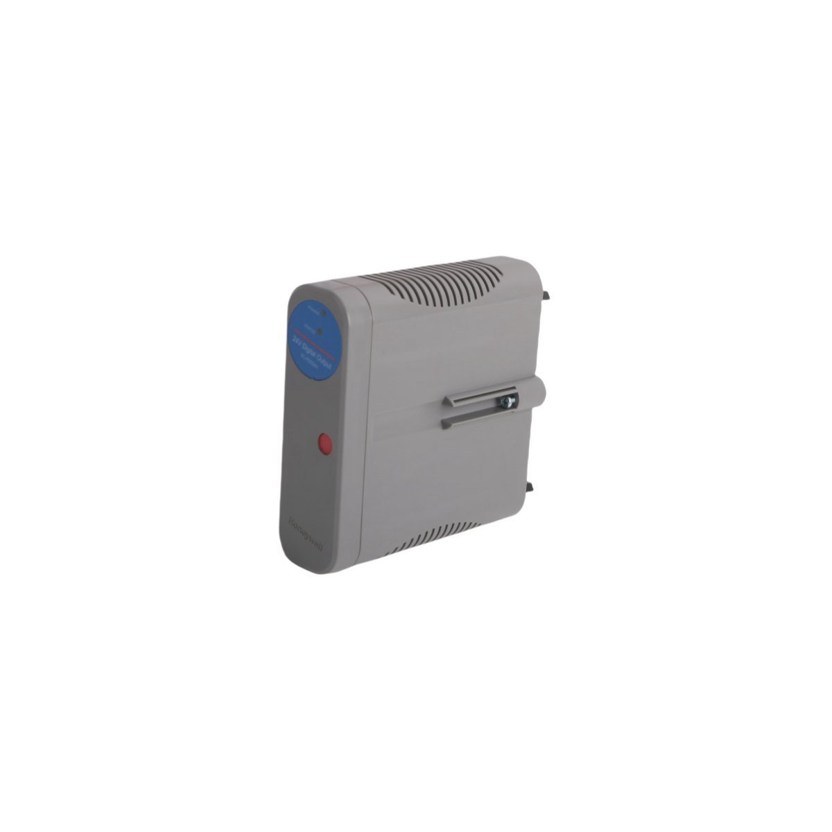
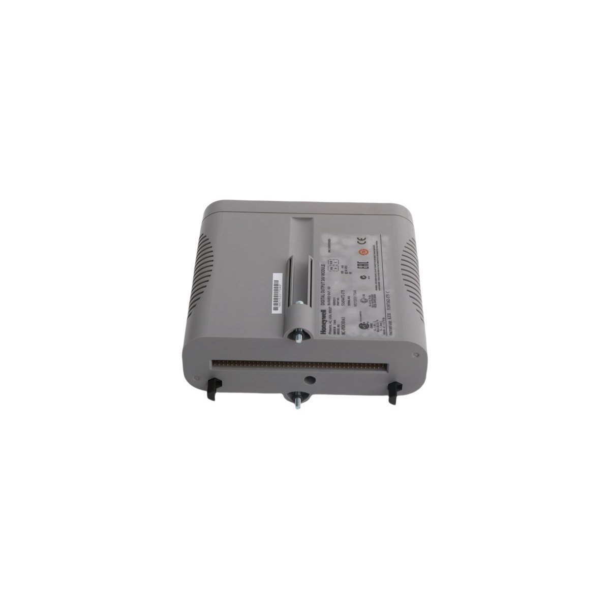
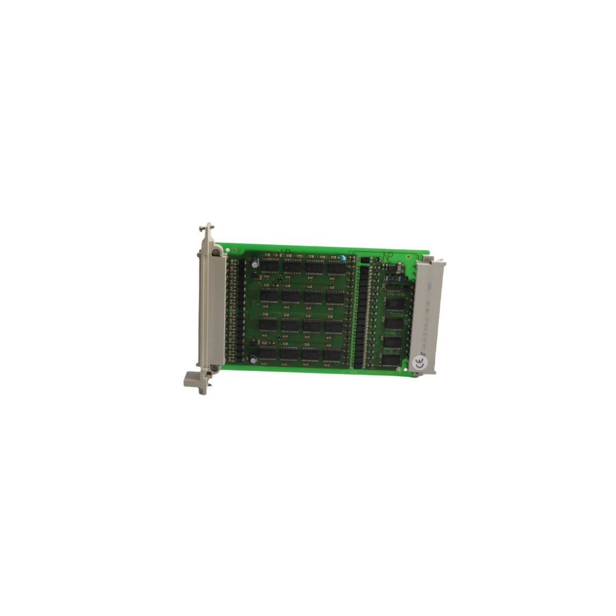
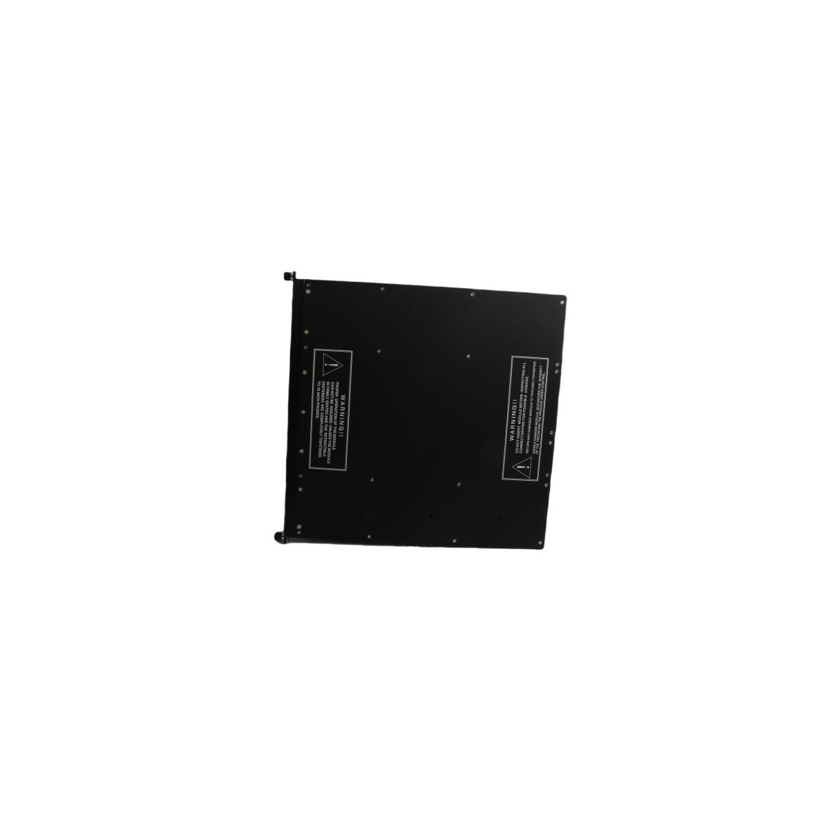
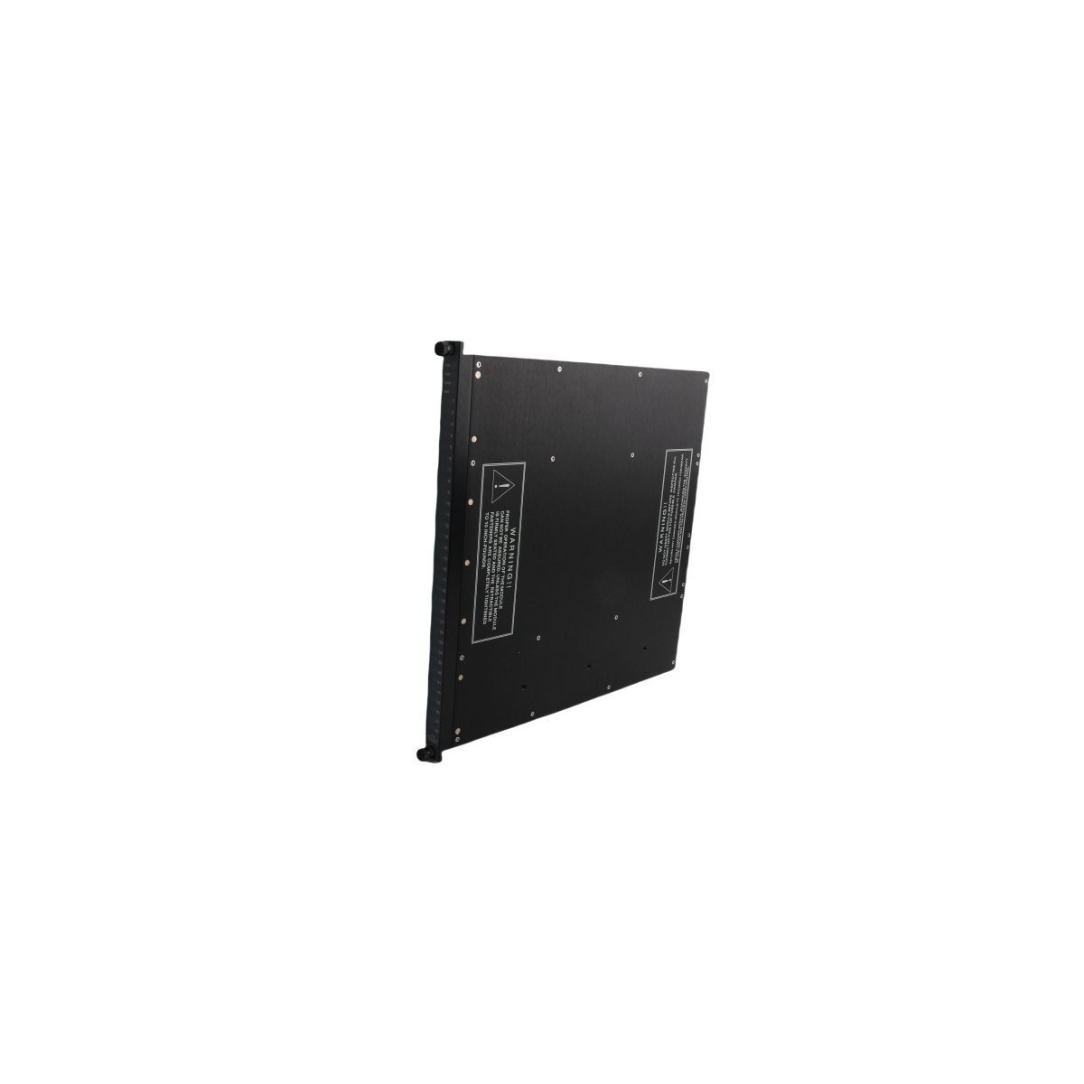
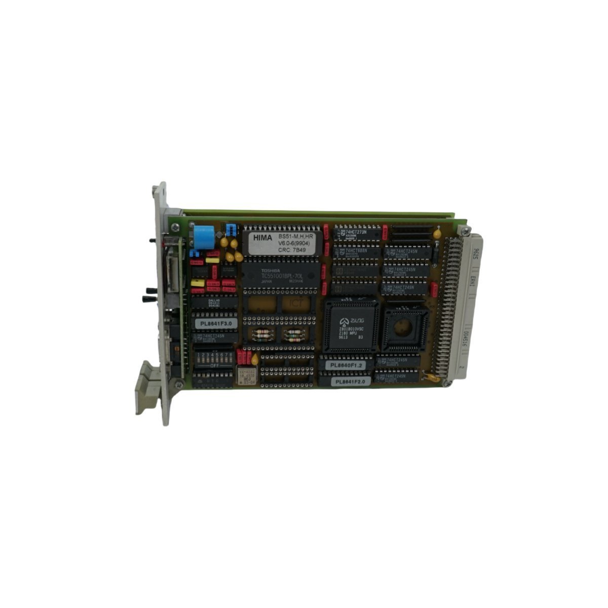
Configured for high-density digital signal switching in Series 8 DCS platforms, the Honeywell 8C-PDODA1 51454472-175 (8C-PDODA1 Digital Output Module) provides direct physical electrical execution for discrete process control.
Hardware Specifications
Parameter
Specification
Model
8C-PDODA1 51454472-175
Brand
Honeywell
Origin
USA
Weight
0.34 kg
Dimensions
6 x 15.2 x 14.3 cm
Operating Temp
Industrial standard
Power Consumption
System-bus dependent
Module Type
Digital Output Module
Process Control & Signal Characteristics
The 8C-PDODA1 module utilizes high-speed logic circuits to execute command signals for field-level discrete actuators and solenoids. The architecture implements channel-to-channel isolation to prevent the propagation of transient surges between output loops, effectively maintaining electrical integrity across the DCS backplane. Each channel is engineered for deterministic switching latency, ensuring precise synchronization within high-speed control loops. Furthermore, the module supports diagnostic feedback paths that monitor output loop continuity, enabling the detection of open-circuit or short-circuit faults before they impact process safety.
Frequently Asked Questions (FAQ)
Q: What are the specific requirements for backplane power distribution when using these modules?
A: The module draws power directly from the Series 8 backplane. Users must ensure that the aggregate current draw of all installed modules does not exceed the power supply capacity of the I/O rack to prevent voltage drops.
Q: Is this module capable of supporting redundant output configurations?
A: Yes, the 8C-PDODA1 supports redundancy. It must be paired with an appropriate redundancy-capable I/O carrier and configured within the Control Builder software to enable seamless failover between primary and secondary modules.
Q: Are there restrictions on the types of inductive loads this module can drive directly?
A: Users must install external flyback diodes across DC inductive loads to mitigate inductive kickback, which can exceed the module’s internal semiconductor ratings and cause hardware failure.
Field Installation Guidelines
To begin with, verify that the module keying is aligned with the I/O carrier slot to prevent incorrect module insertion and potential pin damage.
Subsequently, confirm the backplane is de-energized before mounting the module to avoid arc discharge on the connector pins.
In the interim, while the module is being seated, ensure the alignment remains consistent to prevent mechanical stress.
Meanwhile, tighten the captive screws located on the module faceplate to ensure secure grounding of the module chassis to the rack assembly.
Moreover, as a secondary measure for structural integrity, check that the module is fully flush with the carrier assembly.
Furthermore, ensure all field wiring is terminated at the removable terminal block with the correct torque, following the established loop drawings to prevent cross-channel signal mapping errors.
Additionally, once the wiring is secured, double-check the connection points against the wiring schedule for verification.
Finally, perform a cold-start diagnostic check via the engineering station to confirm successful module initialization and communication with the controller.
The Allen-Bradley 1756-OA16I is a 16-point isolated AC digital output module for ControlLogix systems. It supports 75-265 VAC operation and 2A per point current capacity. This reliable 120/240V module provides per-channel isolation for demanding industrial control applications.
The Allen-Bradley 1771-OA is an 8-channel AC output module for PLC-5 systems. It supports 92-138V AC loads with a 1.5A continuous current per point. This module includes built-in fuse protection and status indicators for reliable industrial automation and device control.
The Yokogawa ADV551-P03 S2 is a 32-channel digital output module for CENTUM VP systems. It provides reliable 24V DC switching and optical isolation for field device control. This compact module supports hot-swapping for high-availability industrial automation.
The Yokogawa ADV551-P00 S2 is a 32-channel digital output module for CENTUM VP systems.It features 24V DC isolated transistor outputs and supports PWM and pulse modes. This Japan-made module offers high-speed switching and hot-swap capabilities for reliable process control.
The Triconex DO3201 is a TMR (Triple Modular Redundant) digital output module designed for the Triconex Safety System.It features SIL3 certification from TÜV Rheinland and provides fault-tolerant control for emergency shutdown and critical safety applications in high-risk industrial environments.
The Triconex DO 3401S2 is a 16-point TMR digital output module designed for SIL 3 safety-critical applications.Featuring independent channel isolation and a fault-tolerant redundant architecture, it provides reliable control for actuators and solenoid valves in the most demanding industrial environments
The Yokogawa NFDV561-P00 S2 is a high-density 64-channel Digital Output Module for CENTUM VP systems. Featuring a 24VDC current sink design and 100mA capacity per channel, this module offers reliable, high-precision control for valves, relays, and indicators in demanding industrial settings.
The ICS Triplex T8451 is a 40-channel, 24VDC TMR Digital Output module designed for the Trusted Safety System.It features SIL 3 integrity, integrated line fault diagnostics, and full voltage/current monitoring for every channel.This fault-tolerant module ensures maximum reliability for critical Emergency Shutdown (ESD) and Fire & Gas applications.
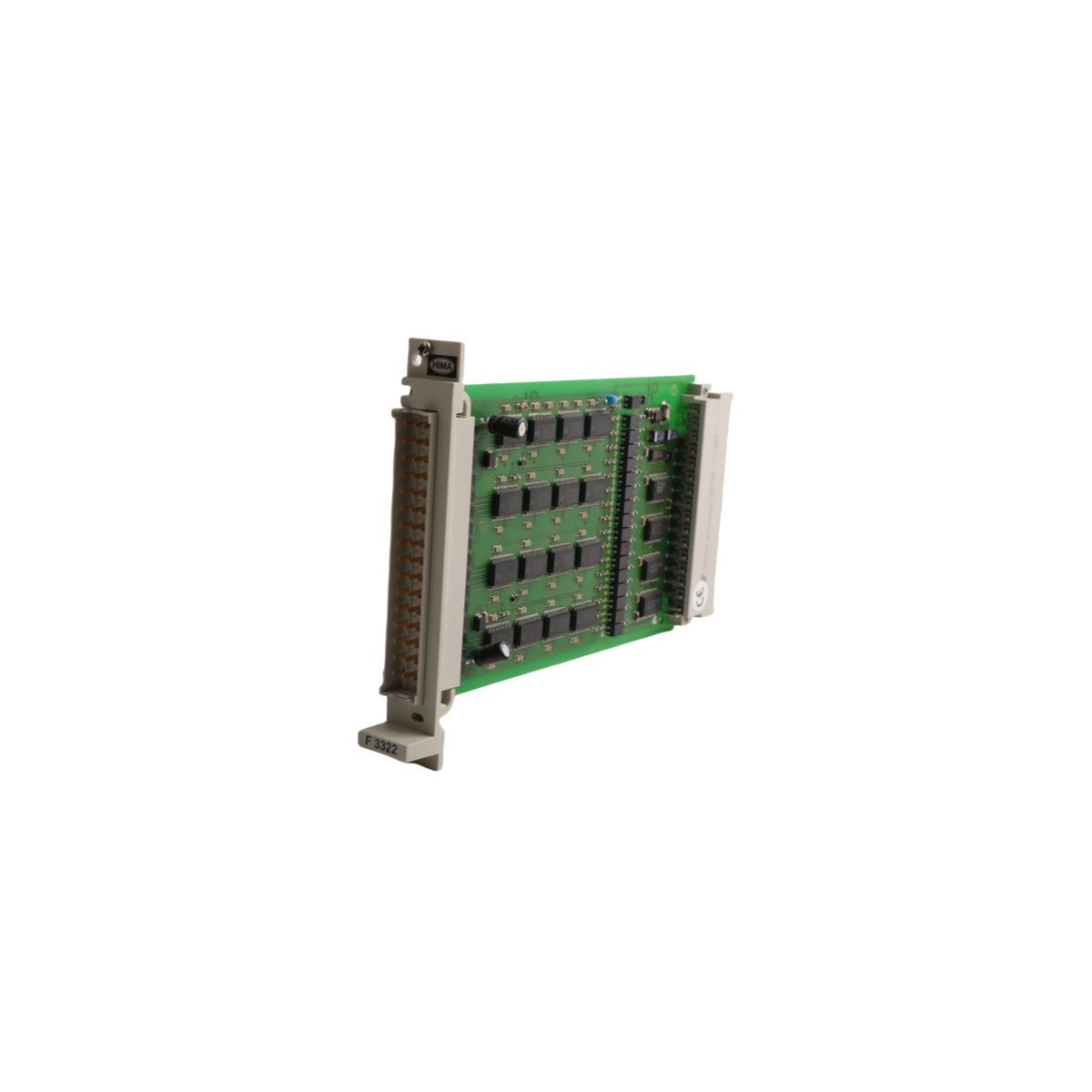
The HIMA F3322 is a high-density 16-channel safety-related digital output module designed for H41q and H51q systems. It offers integrated short-circuit protection and comprehensive diagnostics for reliable control of actuators in SIL-rated environments.
The Triconex 3625N is a 16-channel, 24V DC Digital Output module featuring Triple Modular Redundancy (TMR).SIL 3 certified and hot-swappable, it provides unparalleled fault tolerance and safety-critical control for Emergency Shutdown and Fire and Gas systems.
The Yokogawa SDV531-S33 is an 8-channel digital output module designed for the ProSafe-RS Safety Instrumented System. It provides SIL3-certified performance with advanced self-diagnostics for emergency shutdown and fire and gas applications. This robust, Japan-made safety module ensures mission-critical reliability and rapid response in hazardous industrial environments.
The HIMA F8641 is a safety-related Digital Output Module designed for H41q and H51q systems. This German-engineered module ensures fail-safe operation and high-integrity switching for critical actuators and valves in SIL-rated safety loops.
We are committed to protecting your privacy. The information collected here is strictly used to provide the requested quotes, technical support, and relevant industrial automation solutions.